
Subscribe to Our Youtube Channel
Related Manuals for WAGO 750 Series


Summary of Contents for WAGO 750 Series
- Page 1 Manual WAGO I/O SYSTEM 750 750-498 8AI; TC; Adjust 8-Channel Analog Input; Thermocouple; Adjustable Version 1.0.0...
- Page 2 We wish to point out that the software and hardware terms as well as the trademarks of companies used and/or mentioned in the present manual are generally protected by trademark or patent. WAGO is a registered trademark of WAGO Verwaltungsgesellschaft mbH. Manual Version 1.0.0...
-
Page 3: Table Of Contents
Legal Bases .................... 9 2.1.1 Subject to Changes ................9 2.1.2 Personnel Qualifications ..............9 2.1.3 Use of the 750 Series in Compliance with Underlying Provisions ..9 2.1.4 Technical Condition of Specified Devices......... 10 2.1.4.1 Disposal ..................10 2.1.4.1.1 Electrical and Electronic Equipment ........ - Page 4 Connect Devices ..................53 ® Connecting a Conductor to the Push-in CAGE CLAMP ...... 53 Connection Example ................54 Commissioning ..................55 Parameterization with WAGO-I/O-CHECK ..........55 7.1.1 Parameterization Dialog ..............57 7.1.1.1 Title Bar ..................58 7.1.1.2 Main Menu .................. 59 7.1.1.3...
- Page 5 WAGO I/O SYSTEM 750 Table of Contents 750-498 8AI; TC; Adjust Diagnostics....................84 I/O Module Behavior in the Event of an Error ........84 Appendix ....................86 Configuration and Parameterization using a GSD File with PROFIBUS DP and PROFINET IO ............86 9.1.1...
-
Page 6: Notes About This Documentation
Consider power layout of the WAGO I/O SYSTEM 750! In addition to these operating instructions, you will also need the manual for the used fieldbus coupler or controller, which can be downloaded at www.wago.com. There, you can obtain important information including information on electrical isolation, system power and supply specifications. -
Page 7: Symbols
WAGO I/O SYSTEM 750 Notes about this Documentation 750-498 8AI; TC; Adjust Symbols Personal Injury! Indicates a high-risk, imminently hazardous situation which, if not avoided, will result in death or serious injury. Personal Injury Caused by Electric Current! Indicates a high-risk, imminently hazardous situation which, if not avoided, will result in death or serious injury. -
Page 8: Number Notation
Notes about this Documentation WAGO I/O SYSTEM 750 750-498 8AI; TC; Adjust Additional Information: Refers to additional information which is not an integral part of this documentation (e.g., the Internet). Number Notation Table 2: Number Notation Number Code Example Note... -
Page 9: Important Notes
2.1.1 Subject to Changes WAGO Kontakttechnik GmbH & Co. KG reserves the right to provide for any alterations or modifications. WAGO Kontakttechnik GmbH & Co. KG owns all rights arising from the granting of patents or from the legal protection of utility patents. -
Page 10: Technical Condition Of Specified Devices
These modules contain no parts that can be serviced or repaired by the user. The following actions will result in the exclusion of liability on the part of WAGO Kontakttechnik GmbH & Co. KG: •... -
Page 11: 2.1.4.1.2 Packaging
WAGO I/O SYSTEM 750 Important Notes 750-498 8AI; TC; Adjust • Observe national and local regulations for the disposal of electrical and electronic equipment. • Clear any data stored on the electrical and electronic equipment. • Remove any added battery or memory card in the electrical and electronic equipment. -
Page 12: Safety Advice (Precautions)
Important Notes WAGO I/O SYSTEM 750 750-498 8AI; TC; Adjust Safety Advice (Precautions) For installing and operating purposes of the relevant device to your system the following safety precautions shall be observed: Do not work on devices while energized! All power sources to the device shall be switched off prior to performing any installation, repair or maintenance work. - Page 13 WAGO I/O SYSTEM 750 Important Notes 750-498 8AI; TC; Adjust Ensure proper contact with the DIN-rail! Proper electrical contact between the DIN-rail and device is necessary to maintain the EMC characteristics and function of the device. Replace defective or damaged devices! Replace defective or damaged device/module (e.g., in the event of deformed...
- Page 14 Important Notes WAGO I/O SYSTEM 750 750-498 8AI; TC; Adjust Avoid electrostatic discharge! The devices are equipped with electronic components that may be destroyed by electrostatic discharge when touched. Please observe the safety precautions against electrostatic discharge per DIN EN 61340-5-1/-3. When handling the devices, please ensure that environmental factors (personnel, work space and packaging) are properly grounded.
-
Page 15: Device Description
If cold junction compensation is active, you can choose between internal and external cold junction compensation (see section “Startup” > … > “Parameteri- zation with WAGO-I/O-CHECK“ > … > menu item “Channel settings”). When using external cold junction compensation, you specify the cold junction temperature via WAGO-I/O-CHECK. - Page 16 The device may be used only in dry, indoor rooms. Observe the installation instructions. The 750-498 module can be used with the fieldbus couplers and controllers of the WAGO I/O SYSTEM 750 of the specified version or higher listed in the “Compatibility list” table. Manual...
-
Page 17: Table 4: Compatibility List 750-498
WAGO I/O SYSTEM 750 Device Description 750-498 8AI; TC; Adjust Table 4: Compatibility List 750-498 Bus System Fieldbus Coupler/Controller Item No.. Firmware Version 750-375 PROFINET Fieldbus coupler 750-377 Fieldbus coupler 750-333 PROFIBUS Programmable fieldbus controller 750-833 750-342 Fieldbus coupler 750-352... -
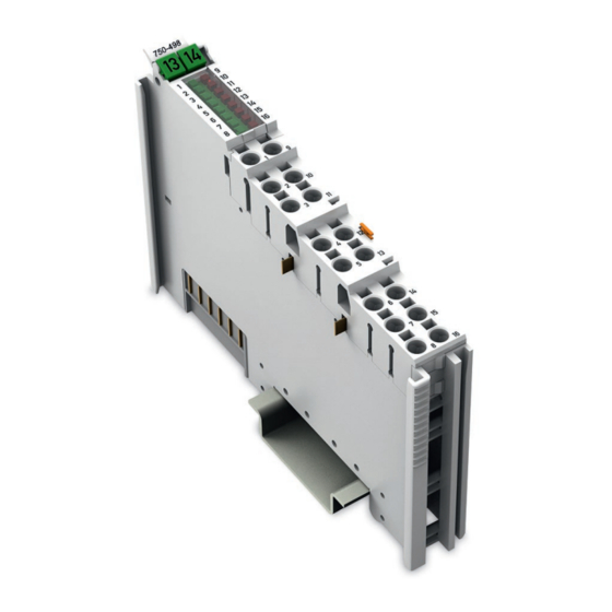
Page 18: View
Device Description WAGO I/O SYSTEM 750 750-498 8AI; TC; Adjust View Figure 1: View of device Table 5: Legend for Figure “View” Pos. Description Details See Section Marking possibility with Mini- Status LEDs “Device Description” > “Display Elements” Data contacts “Device Description”... -
Page 19: Connectors
WAGO I/O SYSTEM 750 Device Description 750-498 8AI; TC; Adjust Connectors 3.2.1 Data Contacts/Local Bus Communication between the fieldbus coupler/controller and the I/O modules as well as the system supply of the I/O modules is carried out via the local bus. The contacting for the local bus consists of 6 data contacts, which are available as self-cleaning gold spring contacts. -
Page 20: Power Jumper Contacts/Field Supply
Device Description WAGO I/O SYSTEM 750 750-498 8AI; TC; Adjust 3.2.2 Power Jumper Contacts/Field Supply Risk of injury due to sharp-edged blade contacts! The blade contacts are sharp-edged. Handle the I/O module carefully to prevent injury. Do not touch the blade contacts. -
Page 21: Push-In Cage Clamp ® Connectors
WAGO I/O SYSTEM 750 Device Description 750-498 8AI; TC; Adjust ® 3.2.3 Push-in CAGE CLAMP Connectors ® Figure 4: Push-in CAGE CLAMP Connections Manual Version 1.0.0... -
Page 22: Table 7: Legend For The "Push-In Cage Clamp ® Connections" Figure
Device Description WAGO I/O SYSTEM 750 750-498 8AI; TC; Adjust ® Table 7: Legend for the “Push-in CAGE CLAMP Connections” Figure – 8-Channel, 2-Wire Channe Designation Connection Function Thermocouple 1: Positive, differential +TC1 measurement voltage input (+) Thermocouple 1: Negative, differential −TC1... -
Page 23: Display Elements
WAGO I/O SYSTEM 750 Device Description 750-498 8AI; TC; Adjust Display Elements Figure 5: Display Elements Table 8: Legend for the “Display Elements” Chan- Designation LED State Function Figure Not ready for operation or no/faulty local bus communication and/or channel... -
Page 24: Operating Elements
Device Description WAGO I/O SYSTEM 750 750-498 8AI; TC; Adjust Operating Elements The I/O module 750-498 has no operating elements. Schematic Diagram Figure 6: Schematic switching diagram Manual Version 1.0.0... -
Page 25: Technical Data
WAGO I/O SYSTEM 750 Device Description 750-498 8AI; TC; Adjust Technical Data 3.6.1 Device Data Table 9: Technical Data, Device Width 12 mm Height (from upper-edge of DIN rail) 64 mm Depth 100 mm Weight approx. 49 g 3.6.2 Power Supply... -
Page 26: Inputs
Device Description WAGO I/O SYSTEM 750 750-498 8AI; TC; Adjust 3.6.3 Inputs Table 11: Technical Data, Inputs Number of inputs Connection types 2-conductor connection, single-ended Input resistance ≥ 10 MΩ Module-internal based on a cold junction Cold junction compensation temperature measurement... -
Page 27: Sensor Types And Measuring Accuracies
WAGO I/O SYSTEM 750 Device Description 750-498 8AI; TC; Adjust 3.6.4 Sensor Types and Measuring Accuracies 3.6.4.1 Temperature Measuring Ranges and Measuring Accuracies including Internal Cold Junction Compensation Note the following: The specified measurement accuracy is only reached after about 20 minutes of operation of the I/O module. -
Page 28: Table 12: Technical Data - Temperature Measuring Ranges And Measuring Accuracies Including Internal Cold Junction Compensation For The Nominal Mounting Position And The Floor Mounting Position
Device Description WAGO I/O SYSTEM 750 750-498 8AI; TC; Adjust Table 12: Technical Data ‒ Temperature Measuring Ranges and Measuring Accuracies including Internal Cold Junction Compensation for the Nominal Mounting Position and the Floor Mounting Position Sensor Type Temperature Range Measuring Accuracy +200 °C …... -
Page 29: Temperature Measuring Ranges And Measuring Accuracies With External Cold Junction Compensation
WAGO I/O SYSTEM 750 Device Description 750-498 8AI; TC; Adjust 3.6.4.2 Temperature Measuring Ranges and Measuring Accuracies with External Cold Junction Compensation Mounting position and air movement have no impact on the measurement accuracy. Table 14: Technical Data ‒ Temperature Measuring Ranges and Measuring Accuracies with External... -
Page 30: Communication
Device Description WAGO I/O SYSTEM 750 750-498 8AI; TC; Adjust 3.6.5 Communication Table 16: Technical Data, Communication Data width internal (local bus) 8-channel operation 8 × 16-bit data 8 × 8-bit control/status (optional) 3.6.6 Connection Type Table 17: Technical Data ‒ Field Wiring ®... -
Page 31: Approvals
WAGO I/O SYSTEM 750 Device Description 750-498 8AI; TC; Adjust Approvals The following approvals have been granted to 750-498 I/O modules: Conformity Marking Korea Certification MSIP-REM-W43-AIM750 Standards and Guidelines 750-498 I/O modules meet the following standards and guidelines: EU EMC Directive... -
Page 32: Process Image
Process Image WAGO I/O SYSTEM 750 750-498 8AI; TC; Adjust Process Image Mapping of process data in the process image of fieldbus systems The representation of the process data of some I/O modules or their variants in the process image depends on the fieldbus coupler/controller used. Please take this information from the section “I/O Modules”... -
Page 33: Overview
The I/O module always makes its complete process image incl. control/status bytes available to the fieldbus coupler/controller. The WAGO-I/O-CHECK commissioning tool accesses the complete commissioning process image. The fieldbus coupler/controller uses a different process image to stage cyclic process data via the fieldbus. -
Page 34: Status Bytes
Process Image WAGO I/O SYSTEM 750 750-498 8AI; TC; Adjust Status Bytes Status bytes are identically implemented for all channels. Therefore, the following description in this section applies to all status bytes of the I/O module. Table 22: Status Byte CH1_S0... -
Page 35: Process Data
WAGO I/O SYSTEM 750 Process Image 750-498 8AI; TC; Adjust Process Data 4.3.1 Overview of Sensor Types The following table serves as an overview of all supported sensor types. The following sections provide detailed information about the individual sensor types, arranged by ID. -
Page 36: Sensors For Temperature Measurement (°C)
Process Image WAGO I/O SYSTEM 750 750-498 8AI; TC; Adjust 4.3.2 Sensors for Temperature Measurement (°C) 4.3.2.1 Standard Data Format For I/O module 750-498, the temperature values of the sensors are displayed at a resolution of 1 digit per 0.1 °C in one word (16-bit). As a result, 0 °C corresponds to the numeric value 0x0000 and 100 °C to the numeric value... -
Page 37: Table 25: Process Image Type N, Id1, Two's Complement Representation
WAGO I/O SYSTEM 750 Process Image 750-498 8AI; TC; Adjust Table 25: Process Image Type N, ID1, Two's Complement Representation Status Numeric value Temperature Error Byte °C Hex. Binary Hex. Dec. '1000.0000.0000.0000' 0x8000 −32768 0x00 Range violation, cold junction < −200.0 '1111.1000.0011.0000'... -
Page 38: Table 26: Process Image Type J, Id2, Two's Complement Representation
Process Image WAGO I/O SYSTEM 750 750-498 8AI; TC; Adjust Table 26: Process Image Type J, ID2, Two's Complement Representation Status Numeric value Temperature Error Byte °C Hex. Binary Hex. Dec. '1000.0000.0000.0000' 0x8000 −32768 0x00 Range violation, cold junction < −210.0 '1111.0111.1100.1100'... -
Page 39: Table 27: Process Image Type K, Id3, Two's Complement Representation
WAGO I/O SYSTEM 750 Process Image 750-498 8AI; TC; Adjust Table 27: Process Image Type K, ID3, Two's Complement Representation Status Numeric value Temperature Error Byte °C Hex. Binary Hex. Dec. '1000.0000.0000.0000' 0x8000 −32768 0x00 Range violation, cold junction < −200.0 '1111.1000.0011.0000'... -
Page 40: Table 28: Process Image Type S, Id4 And Type R, Id5, Two's Complement
Process Image WAGO I/O SYSTEM 750 750-498 8AI; TC; Adjust Table 28: Process Image Type S, ID4 and Type R, ID5, Two's Complement Representation Status Numeric value Temperature Error Byte °C Hex. Binary Hex. Dec. '1000.0000.0000.0000' 0x8000 −32768 0x00 Range violation, cold junction <... -
Page 41: Table 30: Process Image Type T, Id7, Two's Complement Representation
WAGO I/O SYSTEM 750 Process Image 750-498 8AI; TC; Adjust Table 30: Process Image Type T, ID7, Two's Complement Representation Status Numeric value Temperature Error Byte °C Hex. Binary Hex. Dec. '1000.0000.0000.0000' 0x8000 −32768 0x00 Range violation, cold junction < −200.0 '1111.1000.0011.0000'... -
Page 42: Table 31: Process Image Type C, Id8, Two's Complement Representation
Process Image WAGO I/O SYSTEM 750 750-498 8AI; TC; Adjust Table 31: Process Image Type C, ID8, Two's Complement Representation Status Numeric value Temperature Error Byte °C Hex. Binary Hex. Dec. '1000.0000.0000.0000' 0x8000 −32768 0x00 Range violation, cold junction < 0.0 '0000.0000.0000.0000'... -
Page 43: Sensors For Voltage Measurement (Mv)
WAGO I/O SYSTEM 750 Process Image 750-498 8AI; TC; Adjust 4.3.3 Sensors for Voltage Measurement (mV) 4.3.3.1 Standard Data Format For the voltage measurement with sensor type ±30 mV (ID9), the input range of −30 mV … +30 mV is mapped to a value range of −24000 … +24000 at a resolution of 0.00125 mV. -
Page 44: Table 33: Process Image Voltage Measurement ±60 Mv, Id10, Two's
Process Image WAGO I/O SYSTEM 750 750-498 8AI; TC; Adjust For the voltage measurement with sensor type ±60 mV (ID10), the input range of −60 mV … +60 mV is mapped to a value range of −24000 … +24000 at a resolution of 0.0025 mV. -
Page 45: Table 34: Process Image Voltage Measurement ±120 Mv, Id11, Two's
WAGO I/O SYSTEM 750 Process Image 750-498 8AI; TC; Adjust For the voltage measurement with sensor type ±120 mV (ID11), the input range of −120 mV … +120 mV is mapped to a value range of −24000 … +24000 at a resolution of 0.005 mV. -
Page 46: Table 35: Process Image Voltage Measurement ±240 Mv, Id12, Two's
Process Image WAGO I/O SYSTEM 750 750-498 8AI; TC; Adjust For the voltage measurement with sensor type ±240 mV (ID12), the input range of −240 mV … +240 mV is mapped to a value range of −24000 … +24000 at a resolution of 0.01 mV. -
Page 47: Mounting
• Observe the information in the system manual for overall design and mounting clearances. The following mounting positions are approved for the WAGO-I/O-SYSTEM 750: • Nominal mounting position (horizontal left) • Floor mounting position •... -
Page 48: Figure 8: Floor Mounting Position
Mounting WAGO I/O SYSTEM 750 750-498 8AI; TC; Adjust Figure 8: Floor mounting position Figure 9: Horizontal right mounting position Figure 10: Ceiling mounting position Manual Version 1.0.0... -
Page 49: Mounting Sequence
Figure 11: Vertical top and vertical bottom mounting positions Mounting Sequence Fieldbus couplers, controllers and I/O modules of the WAGO I/O SYSTEM 750 are snapped directly on a carrier rail in accordance with the European standard EN 60175 (DIN 35). - Page 50 Always plug a bus end module (750-600) onto the end of the fieldbus node! You must always use a bus end module at all fieldbus nodes with WAGO I/O SYSTEM 750 fieldbus couplers or controllers to guarantee proper data transfer.
-
Page 51: Inserting And Removing Devices
WAGO I/O SYSTEM 750 Mounting 750-498 8AI; TC; Adjust Inserting and Removing Devices Do not work when devices are energized! High voltage can cause electric shock or burns. Switch off all power to the device prior to performing any installation, repair or maintenance work. -
Page 52: Removing The I/O Module
Mounting WAGO I/O SYSTEM 750 750-498 8AI; TC; Adjust 5.3.2 Removing the I/O Module Remove the I/O module from the assembly by pulling the release tab. Figure 14: Removing the I/O Module (Example) Electrical connections for data or power jumper contacts are disconnected when removing the I/O module. -
Page 53: Connect Devices
Do not connect more than one conductor at one single connection! If more than one conductor must be routed to one connection, these must be connected in an up-circuit wiring assembly, for example using WAGO feed- through terminals. Terminate both solid and stranded or ferruled conductors by simply pushing them ®... -
Page 54: Connection Example
Connect Devices WAGO I/O SYSTEM 750 750-498 8AI; TC; Adjust Connection Example Use shielded signal lines! Only use shielded signal lines for analog signals and I/O modules which are equipped with shield clamps. Only then can you ensure that the accuracy and interference immunity specified for the respective I/O module can be achieved even in the presence of interference acting on the signal cable. -
Page 55: Commissioning
Calibration of channels and adjustment of analog inputs • Monitoring WAGO-I/O-CHECK You can obtain the WAGO-I/O-CHECK software on a CD under Item No. 759-302. This CD contains all the application program files and an explanation. You can find a description at the internet page at http://www.wago.com... -
Page 56: Figure 17: Wago-I/O-Check User Interface
To open specific parameterization dialogs for the I/O module 750-498, proceed as follows: Right click on the I/O module. Click the Settings menu item (see following figure). Figure 17: WAGO-I/O-CHECK User Interface The configuration dialog appears. This forms the basis for the subsequent explanation. Manual... -
Page 57: Parameterization Dialog
WAGO I/O SYSTEM 750 Commissioning 750-498 8AI; TC; Adjust 7.1.1 Parameterization Dialog The parameterization dialog is divided into the following areas: Figure 18: Parameterization Dialog for the I/O Module 750-498 Title bar Horizontal tab menu Main menu Vertical tab menu... -
Page 58: Title Bar
Commissioning WAGO I/O SYSTEM 750 750-498 8AI; TC; Adjust 7.1.1.1 Title Bar The title bar in the parameterization dialog contains the program icon, a window title and buttons for exiting, minimizing and maximizing the application window. Figure 19: Title Bar in the Parameterization Dialog The window title provides information about the position of the I/O module within the fieldbus node used and the item number of the selected I/O module. -
Page 59: Main Menu
WAGO I/O SYSTEM 750 Commissioning 750-498 8AI; TC; Adjust 7.1.1.2 Main Menu Table 36: Buttons in the Main Menu Button Function Description Creates a connection to the [Connect] I/O module. Interrupts an existing connection to [Disconnect] the I/O module. Reads all parameters of the... -
Page 60: Horizontal Tab Menu
Commissioning WAGO I/O SYSTEM 750 750-498 8AI; TC; Adjust 7.1.1.3 Horizontal Tab Menu The horizontal tab menu contains the following tabs: Figure 20: Horizontal Tab Menu Click one of the tabs to display the respective selection options in the main menu. -
Page 61: 7.1.1.3.1 "File" Tab
WAGO I/O SYSTEM 750 Commissioning 750-498 8AI; TC; Adjust 7.1.1.3.1 “File” Tab The File tab opens the application menu that contains the following buttons. Figure 21: Buttons in the Application Menu Table 37: Buttons in the Application Menu Button Function... -
Page 62: Open" Menu Item
“Open” Menu Item Only open parameter files created with WAGO-I/O-CHECK Please note that only parameter files created with WAGO-I/O-CHECK can be opened. The parameter files have the extension *.tc . In this menu item you can open and load an existing parameter file. -
Page 63: Save" Menu Item
WAGO I/O SYSTEM 750 Commissioning 750-498 8AI; TC; Adjust 7.1.1.3.1.2 “Save” Menu Item Calibration settings are not saved Please note that the calibration settings cannot be saved in the parameter file. Note the memory range Please note that only the settings are saved in the parameter file that you have... -
Page 64: 7.1.1.3.2 "Start" Tab
Commissioning WAGO I/O SYSTEM 750 750-498 8AI; TC; Adjust 7.1.1.3.2 “Start” Tab Click the Start tab in the horizontal tab menu to display the following selection options in the main menu. Figure 22: Contents of the Horizontal Tab Start The individual functions are described in subsection “Configuration Dialog” >... -
Page 65: 7.1.1.3.3 "Connection" Tab
WAGO I/O SYSTEM 750 Commissioning 750-498 8AI; TC; Adjust 7.1.1.3.3 “Connection” Tab Click the Connection tab in the horizontal tab menu to display the following selection options in the main menu. If the is no connection to the I/O module, the following button appears: Figure 24: Connection Tab for Disconnected I/O Module Click the [Connect] button to establish a connection to the I/O module. -
Page 66: Vertical Tab Menu
Commissioning WAGO I/O SYSTEM 750 750-498 8AI; TC; Adjust 7.1.1.4 Vertical Tab Menu In the vertical tab menu, you can select the individual module- and channel- specific menu items. Figure 26: Overview of the Vertical Tab Menu Click one of the menu items to call up the related parameterization options in the application area. -
Page 67: 7.1.1.4.1 "Module Settings" Menu Item
WAGO I/O SYSTEM 750 Commissioning 750-498 8AI; TC; Adjust 7.1.1.4.1 “Module settings” Menu Item Figure 27: Module settings Menu Item View Table 38: Module settings Menu Item Option Description Watchdog Timer The watchdog timer is activated. Deactivate watchdog The watchdog timer is deactivated. -
Page 68: 7.1.1.4.2 "Channel Settings" Menu Item
Commissioning WAGO I/O SYSTEM 750 750-498 8AI; TC; Adjust 7.1.1.4.2 “Channel settings” Menu Item Note choice of sensor types for cold junction compensation! Cold junction compensation can only be configured if you select a thermocouple as the sensor type under the Channel settings menu item in the vertical tab menu. -
Page 69: Figure 28: Channel Settings Menu Item View
WAGO I/O SYSTEM 750 Commissioning 750-498 8AI; TC; Adjust Figure 28: Channel settings Menu Item View Manual Version 1.0.0... -
Page 70: Table 39: Channel Settings Menu Item
Commissioning WAGO I/O SYSTEM 750 750-498 8AI; TC; Adjust Table 39: Channel settings Menu Item Option Description General Settings The channel selected in the main menu is deactivated. If the channel is deactivated, “0x7FFF” appears in the Deactivate channel “Monitoring”... - Page 71 WAGO I/O SYSTEM 750 Commissioning 750-498 8AI; TC; Adjust Table 39: Channel settings Menu Item Option Description Diagnostics Diagnosis functions are activated globally and are displayed in the status byte. Activate diagnosis Diagnosis functions are deactivated globally. functions globally Note: If diagnoses are deactivated globally, the following diagnoses cannot be selected individually.
-
Page 72: 7.1.1.4.3 "Scaling" Menu Item
Commissioning WAGO I/O SYSTEM 750 750-498 8AI; TC; Adjust 7.1.1.4.3 “Scaling” Menu Item Figure 29: Scaling Menu Item View Table 40: Scaling Menu Item Option Description Channel x User scaling is activated. By enabling this setting, you can also ... -
Page 73: 7.1.1.4.4 "Calibration" Menu Item
WAGO I/O SYSTEM 750 Commissioning 750-498 8AI; TC; Adjust 7.1.1.4.4 “Calibration” Menu Item Automatic activation of user calibration! The user calibration is automatically activated by clicking the vertical Calibration tab. The I/O module always has the sensor type group ±30 mV as the default. The values for Gain and Offset are read from the I/O module. -
Page 74: Table 41: Calibration Menu Item
Commissioning WAGO I/O SYSTEM 750 750-498 8AI; TC; Adjust Table 41: Calibration Menu Item Option Description User calibration Sensor type group contains the Sensor type group following sensor types Sensor type S (ID4) Sensor type R (ID5) Sensor type B (ID6) +/−30 mV... -
Page 75: 7.1.1.4.5 "Monitoring" Menu Item
WAGO I/O SYSTEM 750 Commissioning 750-498 8AI; TC; Adjust 7.1.1.4.5 “Monitoring” Menu Item In this area, an overview of all of the I/O module channels is displayed individually. This overview provides information about the process value of each individual I/O module channel. -
Page 76: 7.1.1.4.6 "Information" Menu Item
Commissioning WAGO I/O SYSTEM 750 750-498 8AI; TC; Adjust 7.1.1.4.6 “Information” Menu Item This area provides an overview of the specifications for the I/O module used. You obtain information about the following points: • Article number • Description • Hardware version •... -
Page 77: Status Messages
WAGO I/O SYSTEM 750 Commissioning 750-498 8AI; TC; Adjust 7.1.1.6 Status Messages Activate diagnostics! Activate the diagnostics in the Channel settings menu item to receive status messages! This area provides information about occurring diagnostics. If you have activated diagnostics in the Channel settings menu item and a diagnostic occurs, the diagnostic is displayed in the status messages window. -
Page 78: Figure 34: Status Messages In The Application Window Of The
Commissioning WAGO I/O SYSTEM 750 750-498 8AI; TC; Adjust The status messages are displayed with corresponding assignment of the relevant I/O module channels. Figure 34: Status Messages in the Application Window of the Parameterization Dialog Click the [Delete] button to clear the status message history. The history is automatically cleared if you interrupt the connection to the I/O module or close the parameterization dialog. -
Page 79: Status Bar
WAGO I/O SYSTEM 750 Commissioning 750-498 8AI; TC; Adjust 7.1.1.7 Status Bar The following information is displayed in the status bar: • Status indication with display of the currently executed action as text or the respective error message if an error occurs •... -
Page 80: Calibrating Measured Values
Commissioning WAGO I/O SYSTEM 750 750-498 8AI; TC; Adjust Calibrating Measured Values Sensors are calibrated by sensor type group! Calibration is always performed for the selected sensor type group and must be repeated for all other sensor type groups that need to be calibrated. -
Page 81: Example Of Determining Gain And Offset
7.3.1 Example of Determining Gain and Offset Perform the following steps in WAGO-I/O-CHECK: 1. In the vertical tab menu, select the “Channel settings” menu item. 2. In the horizontal tab menu, select Channel 1 from the list box and enable the option “Use user calibration”... - Page 82 = (y1 / m) – x1 b = (100 mV/ 1.015) − 101 mV= −2.478 mV 12. Enter the value calculated for calibration gain (1.015) in WAGO-I/O-CHECK. 13. Convert the result for the calibration offset from millivolt to microvolt.
-
Page 83: Scaling Measured Values
WAGO I/O SYSTEM 750 Commissioning 750-498 8AI; TC; Adjust </dg_ Scaling Measured Values User scaling serves to adjust the process values. When user scaling is used, the required accuracy of the process value resolution is changed, but not fundamentally limited. User scaling is optional. -
Page 84: Table 46: Priority Levels Of Diagnostic Functions
You can activate or deactivate these diagnostics individually in WAGO-I/O-CHECK (see section “Startup” > … > “Parameterization with WAGO-I/O-CHECK” > … > menu item “Channel settings”). The I/O module only allows one error to be indicated. A dedicated bit in the status byte is assigned to each error status. -
Page 85: Table 47: Behavior In The Event Of An I/O Module Error Dependent On The
WAGO I/O SYSTEM 750 Diagnostics 750-498 8AI; TC; Adjust Table 47: Behavior in the Event of an I/O Module Error Dependent on the Configuration Configuration I/O module behavior for I/O module behavior for Underrange/ Wire break range violation wire break... -
Page 86: Configuration 8 Ai Tc
Appendix WAGO I/O SYSTEM 750 750-498 8AI; TC; Adjust Appendix Configuration and Parameterization using a GSD File with PROFIBUS DP and PROFINET IO 9.1.1 Configuration 8 AI TC 9.1.1.1 PROFIBUS DP Fieldbus Coupler/Controller 750-333(/0xx-000), 750-833(/0xx-000) When using the aforementioned PROFIBUS DP fieldbus devices, the process image size is configured by selecting the corresponding GSD entry. -
Page 87: Parameterization 8 Ai Tc
WAGO I/O SYSTEM 750 Appendix 750-498 8AI; TC; Adjust 9.1.2 Parameterization 8 AI TC Apart from the user limits, the GSD file can be used to provide the I/O module on the PROFIBUS DP and PROFINET IO fieldbus coupler with all operating parameters. -
Page 88: Figure 37: Example Of The 750-370 Fieldbus Coupler Parameterization
Appendix WAGO I/O SYSTEM 750 750-498 8AI; TC; Adjust Figure 37: Example of the 750-370 fieldbus coupler parameterization dialog Manual Version 1.0.0... -
Page 89: All Profibus Dp And Profinet Io Fieldbus Couplers
WAGO I/O SYSTEM 750 Appendix 750-498 8AI; TC; Adjust For the PROFINET IO fieldbus couplers 750-375(/025-000) and 750-377(/025-000) the channel´s user limits can be adjusted via GSD, too. On input values falling below or exceeding those limits, a respective process alarm will be issued. -
Page 90: Profibus Dp Fieldbus Coupler 750-333(/0Xx-000), 750-833(/0Xx-000)
Appendix WAGO I/O SYSTEM 750 750-498 8AI; TC; Adjust Table 51: Specific module / channel parameters for 750-498 GSD File WAGO-I/O-CHECK Description Value Selection box Value Type J [DIN EN 60584-1] Type J [DIN EN 60584-1] Type K [DIN EN 60584-1]... -
Page 91: Profinet Io Fieldbus Coupler 750-370, 750-375(/025-000), 750-377(/025-000)
WAGO I/O SYSTEM 750 Appendix 750-498 8AI; TC; Adjust 9.1.2.3 PROFINET IO Fieldbus Coupler 750-370, 750-375(/025-000), 750-377(/025-000) The aforementioned fieldbus couplers allow module-specific parameterization of behavior at diagnosis. Table 53: General module / channel parameters Parameter Value Explanation Channel diagnosis... -
Page 92: Table 53: General Module / Channel Parameters
Appendix WAGO I/O SYSTEM 750 750-498 8AI; TC; Adjust Table 53: General module / channel parameters Parameter Value Explanation Process alarm: 0 (false) Falling below the lower user limit on the Lower user limit value respective signal channel does not lead to undershot transmission of a process alarm. - Page 93 Figure 15: Connecting a Conductor to a Push-in CAGE CLAMP ......53 Figure 16: Connection example – 2-Wire ............54 Figure 17: WAGO-I/O-CHECK User Interface ............56 Figure 18: Parameterization Dialog for the I/O Module 750-498 ......57 Figure 19: Title Bar in the Parameterization Dialog ..........58 Figure 20: Horizontal Tab Menu .................60...
- Page 94 List of Tables WAGO I/O SYSTEM 750 750-498 8AI; TC; Adjust List of Tables Table 1: Revision History ..................6 Table 2: Number Notation ................... 8 Table 3: Font Conventions .................. 8 Table 4: Compatibility List 750-498 ..............17 Table 5: Legend for Figure “View” ..............18 Table 6: Legend for Figure “Power Jumper Contacts”...
- Page 95 WAGO I/O SYSTEM 750 List of Tables 750-498 8AI; TC; Adjust Table 35: Process Image Voltage Measurement ±240 mV, ID12, Two's Complement Representation ..............46 Table 36: Buttons in the Main Menu ..............59 Table 37: Buttons in the Application Menu ............61 Table 38: Module settings Menu Item ..............67...
- Page 96 WAGO Kontakttechnik GmbH & Co. KG Postfach 2880 • D - 32385 Minden Hansastraße 27 • D - 32423 Minden Phone: +49 571 887 – 0 Fax: +49 571 887 – 844169 E-Mail: info@wago.com Internet: www.wago.com...
Need help?
Do you have a question about the 750 Series and is the answer not in the manual?
Questions and answers