
Subscribe to Our Youtube Channel
Related Manuals for WAGO 750 Series


Summary of Contents for WAGO 750 Series
- Page 1 WAGO-I/O-SYSTEM 750 Manual 750-1422 4DI 24V DC 3.0ms, low-side switching, 3-conductor 4-Channel Digital Input Module 24 VDC, Low-side Switching, 3-Conductor Connection Version 1.2.0...
- Page 2 WAGO-I/O-SYSTEM 750 750-1422 4DI 24V DC 3.0ms, low-side switching, 3-conductor © 2016 by WAGO Kontakttechnik GmbH & Co. KG All rights reserved. WAGO Kontakttechnik GmbH & Co. KG Hansastraße 27 D-32423 Minden Phone: +49 (0) 571/8 87 – 0 Fax: +49 (0) 571/8 87 –...
-
Page 3: Table Of Contents
2.1.1 Subject to Changes ................9 2.1.2 Personnel Qualifications ............... 9 2.1.3 Use of the WAGO-I/O-SYSTEM 750 in Compliance with Underlying Provisions ................9 2.1.4 Technical Condition of Specified Devices ......... 10 Safety Advice (Precautions) ..............11 Device Description ..................13 View ...................... - Page 4 Table of Contents WAGO-I/O-SYSTEM 750 750-1422 4DI 24V DC 3.0ms, low-side switching, 3-conductor 7.2.2 Special Conditions for Safe Use (ATEX Certificate TÜV 12 ATEX 106032 X) ................40 7.2.3 Special Conditions for Safe Use (IEC-Ex Certificate TUN 09.0001 X) ................. 41 7.2.4...
-
Page 5: Notes About This Documentation
Manual by third parties that violate pertinent copyright provisions is prohibited. Reproduction, translation, electronic and phototechnical filing/archiving (e.g., photocopying) as well as any amendments require the written consent of WAGO Kontakttechnik GmbH & Co. KG, Minden, Germany. Non-observance will involve the right to assert damage claims. Manual... -
Page 6: Symbols
Notes about this Documentation WAGO-I/O-SYSTEM 750 750-1422 4DI 24V DC 3.0ms, low-side switching, 3-conductor Symbols Personal Injury! Indicates a high-risk, imminently hazardous situation which, if not avoided, will result in death or serious injury. Personal Injury Caused by Electric Current! Indicates a high-risk, imminently hazardous situation which, if not avoided, will result in death or serious injury. - Page 7 WAGO-I/O-SYSTEM 750 Notes about this Documentation 750-1422 4DI 24V DC 3.0ms, low-side switching, 3-conductor Additional Information: Refers to additional information which is not an integral part of this documentation (e.g., the Internet). Manual Version 1.2.0...
-
Page 8: Table 1: Number Notation
Table 2: Font Conventions Font Type Indicates italic Names of paths and data files are marked in italic-type. e.g.: C:\Program Files\WAGO Software Menu Menu items are marked in bold letters. e.g.: Save A greater-than sign between two names means the selection of a >... -
Page 9: Important Notes
2.1.1 Subject to Changes WAGO Kontakttechnik GmbH & Co. KG reserves the right to provide for any alterations or modifications that serve to increase the efficiency of technical progress. WAGO Kontakttechnik GmbH & Co. KG owns all rights arising from the granting of patents or from the legal protection of utility patents. -
Page 10: Technical Condition Of Specified Devices
WAGO-I/O-SYSTEM 750 750-1422 4DI 24V DC 3.0ms, low-side switching, 3-conductor Appropriate housing (per 94/9/EG) is required when operating the WAGO-I/O- SYSTEM 750 in hazardous environments. Please note that a prototype test certificate must be obtained that confirms the correct installation of the system in a housing or switch cabinet. -
Page 11: Safety Advice (Precautions)
Install the device only in appropriate housings, cabinets or in electrical operation rooms! The WAGO-I/O-SYSTEM 750 and its components are an open system. As such, install the system and its components exclusively in appropriate housings, cabinets or in electrical operation rooms. Allow access to such equipment and fixtures to authorized, qualified staff only by means of specific keys or tools. - Page 12 Important Notes WAGO-I/O-SYSTEM 750 750-1422 4DI 24V DC 3.0ms, low-side switching, 3-conductor Do not use any contact spray! Do not use any contact spray. The spray may impair contact area functionality in connection with contamination. Do not reverse the polarity of connection lines! Avoid reverse polarity of data and power supply lines, as this may damage the devices involved.
-
Page 13: Device Description
WAGO-I/O-SYSTEM 750 Device Description 750-1422 4DI 24V DC 3.0ms, low-side switching, 3-conductor Device Description The digital input module 750-1422 (4DI 24V DC 3.0ms, low-side switching, 3- conductor) receives control signals from digital field (e.g. of sensors, transmitters, switches or proximity switches). - Page 14 Device Description WAGO-I/O-SYSTEM 750 750-1422 4DI 24V DC 3.0ms, low-side switching, 3-conductor The I/O module 750-1422 can be used with all fieldbus couplers/controllers of the WAGO-I/O-SYSTEM 750. Manual Version 1.2.0...
-
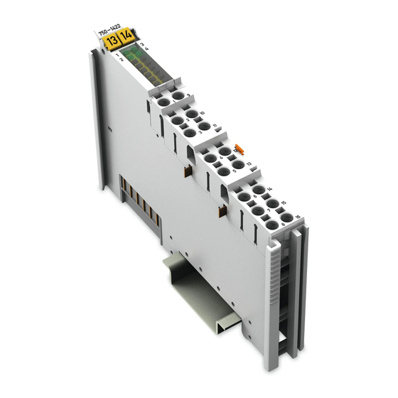
Page 15: View
WAGO-I/O-SYSTEM 750 Device Description 750-1422 4DI 24V DC 3.0ms, low-side switching, 3-conductor View Figure 1: View Table 3: Legend for Figure “View” Pos. Description Details See Section Marking possibility with Mini-WSB Status LEDs “Device Description” > “Display Elements” Data contacts “Device Description”... -
Page 16: Connectors
Device Description WAGO-I/O-SYSTEM 750 750-1422 4DI 24V DC 3.0ms, low-side switching, 3-conductor Connectors 3.2.1 Data Contacts/Internal Bus Communication between the fieldbus coupler/controller and the I/O modules as well as the system supply of the I/O modules is carried out via the internal bus. It is comprised of 6 data contacts, which are available as self-cleaning gold spring contacts. -
Page 17: Power Jumper Contacts/Field Supply
WAGO-I/O-SYSTEM 750 Device Description 750-1422 4DI 24V DC 3.0ms, low-side switching, 3-conductor 3.2.2 Power Jumper Contacts/Field Supply Risk of injury due to sharp-edged blade contacts! The blade contacts are sharp-edged. Handle the I/O module carefully to prevent injury. The I/O module 750-1422 has 2 self-cleaning power jumper contacts that supply and transmit power for the field side. - Page 18 Device Description WAGO-I/O-SYSTEM 750 750-1422 4DI 24V DC 3.0ms, low-side switching, 3-conductor Use supply modules for ground (earth)! The I/O module has no power jumper contacts for receiving and transmitting the earth potential. Use a supply module when an earth potential is needed for the subsequent I/O modules.
-
Page 19: Push-In Cage Clamp ® Connectors
WAGO-I/O-SYSTEM 750 Device Description 750-1422 4DI 24V DC 3.0ms, low-side switching, 3-conductor ® 3.2.3 Push-in CAGE CLAMP Connectors ® Figure 4: Push-in CAGE CLAMP Connectors ® Table 5: Legend for Figure “Push-in CAGE CLAMP Connectors” Channel Designation Connectors Function DI 1... -
Page 20: Display Elements
Device Description WAGO-I/O-SYSTEM 750 750-1422 4DI 24V DC 3.0ms, low-side switching, 3-conductor Display Elements Figure 5: Display Elements Table 6: Legend for Figure “Display Elements“ Channel Designation State Function Input DI 1: Signal voltage (0) Status DI 1 Green Input DI 1: Signal voltage (1) -
Page 21: Schematic Diagram
WAGO-I/O-SYSTEM 750 Device Description 750-1422 4DI 24V DC 3.0ms, low-side switching, 3-conductor Schematic Diagram Figure 6: Schematic Diagram Manual Version 1.2.0... -
Page 22: Technical Data
Device Description WAGO-I/O-SYSTEM 750 750-1422 4DI 24V DC 3.0ms, low-side switching, 3-conductor Technical Data 3.6.1 Device Table 7: Technical Data – Device Width 12 mm Height (from upper edge of 35 DIN rail) 67 mm Depth 100 mm Weight 44.4 g 3.6.2... -
Page 23: Connection Type
WAGO-I/O-SYSTEM 750 Device Description 750-1422 4DI 24V DC 3.0ms, low-side switching, 3-conductor 3.6.5 Connection Type Table 11: Technical Data ‒ Field Wiring ® Wire connection Push-in CAGE CLAMP Cross section, solid wire 0.08 mm² … 1.5 mm² / AWG 28 … 16 Cross section, fine-stranded wire 0.25 mm²... -
Page 24: Approvals
750-1422 4DI 24V DC 3.0ms, low-side switching, 3-conductor Approvals More information about approvals. Detailed references to the approvals are listed in the document “Overview Approvals WAGO-I/O-SYSTEM 750”, which you can find via the internet under: www.wago.com > SERVICES > DOWNLOADS > Additional documentation and information on automation products >... -
Page 25: Standards And Guidelines
WAGO-I/O-SYSTEM 750 Device Description 750-1422 4DI 24V DC 3.0ms, low-side switching, 3-conductor DNV (Det Norske Veritas) Class B GL (Germanischer Lloyd) Cat. A, B, C, D (EMC 1) KR (Korean Register of Shipping) LR (Lloyd’s Register) Env. 1, 2, 3, 4 NKK (Nippon Kaiji Kyokai) PRS (Polski Rejestr Statków) -
Page 26: Process Image
Process Image WAGO-I/O-SYSTEM 750 750-1422 4DI 24V DC 3.0ms, low-side switching, 3-conductor Process Image Table 15: Input Bits Bit 3 Bit 2 Bit 1 Bit 0 DI 4 DI 3 DI 2 DI 1 DI 1 Signal state DI 1 – digital input channel 1 DI 2 Signal state DI 2 –... -
Page 27: Mounting
Don't forget the bus end module! Always plug a bus end module 750-600 onto the end of the fieldbus node! You must always use a bus end module at all fieldbus nodes with WAGO-I/O- SYSTEM 750 fieldbus couplers/controllers to guarantee proper data transfer. -
Page 28: Inserting And Removing Devices
Mounting WAGO-I/O-SYSTEM 750 750-1422 4DI 24V DC 3.0ms, low-side switching, 3-conductor Inserting and Removing Devices Perform work on devices only if they are de-energized! Working on energized devices can damage them. Therefore, turn off the power supply before working on the devices. -
Page 29: Removing The I/O Module
WAGO-I/O-SYSTEM 750 Mounting 750-1422 4DI 24V DC 3.0ms, low-side switching, 3-conductor 5.2.2 Removing the I/O Module Remove the I/O module from the assembly by pulling the release tab. Figure 9: Removing the I/O Module (Example) Electrical connections for data or power jumper contacts are disconnected when removing the I/O module. -
Page 30: Connect Devices
Do not connect more than one conductor at one single connection! If more than one conductor must be routed to one connection, these must be connected in an up-circuit wiring assembly, for example using WAGO feed- through terminals. Terminate both solid and stranded or ferruled conductors by simply pushing them ®... -
Page 31: Use In Hazardous Environments
Use in Hazardous Environments 750-1422 4DI 24V DC 3.0ms, low-side switching, 3-conductor Use in Hazardous Environments The WAGO-I/O-SYSTEM 750 (electrical equipment) is designed for use in Zone 2 hazardous areas. The following sections include both the general identification of components (devices) and the installation regulations to be observed. -
Page 32: Marking Configuration Examples
Use in Hazardous Environments WAGO-I/O-SYSTEM 750 750-1422 4DI 24V DC 3.0ms, low-side switching, 3-conductor Marking Configuration Examples 7.1.1 Marking for Europe According to ATEX and IEC-Ex Figure 11: Side Marking Example for Approved I/O Modules According to ATEX and IECEx Figure 12: Text Detail –... -
Page 33: Table 16: Description Of Marking Example For Approved I/O Modules According To Atex And Iecex
WAGO-I/O-SYSTEM 750 Use in Hazardous Environments 750-1422 4DI 24V DC 3.0ms, low-side switching, 3-conductor Table 16: Description of Marking Example for Approved I/O Modules According to ATEX and IECEx Printing on Text Description TÜV 07 ATEX 554086 X Approving authority and certificate numbers IECEx TUN 09.0001 X... -
Page 34: Figure 13: Side Marking Example For Approved Ex I I/O Modules According To Atex And Iecex
Use in Hazardous Environments WAGO-I/O-SYSTEM 750 750-1422 4DI 24V DC 3.0ms, low-side switching, 3-conductor Figure 13: Side Marking Example for Approved Ex i I/O Modules According to ATEX and IECEx. Figure 14: Text Detail – Marking Example for Approved Ex i I/O Modules According to ATEX and IECEx. - Page 35 WAGO-I/O-SYSTEM 750 Use in Hazardous Environments 750-1422 4DI 24V DC 3.0ms, low-side switching, 3-conductor Table 17: Description of Marking Example for Approved Ex i I/O Modules According to ATEX and IECEx Inscription Text Description TÜV 07 ATEX 554086 X Approving authority and certificate numbers IECEx TUN 09.0001X...
-
Page 36: Table 17: Description Of Marking Example For Approved Ex I I/O Modules According To Atex And Iecex
Use in Hazardous Environments WAGO-I/O-SYSTEM 750 750-1422 4DI 24V DC 3.0ms, low-side switching, 3-conductor Table 17: Description of Marking Example for Approved Ex i I/O Modules According to ATEX and IECEx Gases Equipment group: All except mining 3(1)G Category 3 (Zone 2) equipment containing a safety... -
Page 37: Marking For America According To Nec 500
WAGO-I/O-SYSTEM 750 Use in Hazardous Environments 750-1422 4DI 24V DC 3.0ms, low-side switching, 3-conductor 7.1.2 Marking for America According to NEC 500 Figure 15: Side Marking Example for I/O Modules According to NEC 500 Figure 16: Text Detail – Marking Example for Approved I/O Modules According to NEC 500... -
Page 38: Installation Regulations
Use in Hazardous Environments WAGO-I/O-SYSTEM 750 750-1422 4DI 24V DC 3.0ms, low-side switching, 3-conductor Installation Regulations For the installation and operation of electrical equipment in hazardous areas, the valid national and international rules and regulations which are applicable at the installation location must be carefully followed. -
Page 39: Special Conditions For Safe Use (Atex Certificate Tüv 07 Atex 554086 X)
ATEX 554086 X) For use as Gc- or Dc-apparatus (in zone 2 or 22) the Field bus Independent I/O Modules WAGO-I/O-SYSTEM 750-*** shall be erected in an enclosure that fulfils the requirements of the applicable standards (see the marking) EN 60079-0, EN 60079-11, EN 60079-15 and EN 60079-31. -
Page 40: Special Conditions For Safe Use (Atex Certificate Tüv 12 Atex 106032 X)
ATEX 106032 X) For use as Gc- or Dc-apparatus (in zone 2 or 22) the Field bus Independent I/O Modules WAGO-I/O-SYSTEM 750-*** Ex i shall be erected in an enclosure that fulfils the requirements of the applicable standards (see the marking) EN 60079-0, EN 60079-11, EN 60079-15 and EN 60079-31. -
Page 41: Special Conditions For Safe Use (Iec-Ex Certificate Tun 09.0001 X)
09.0001 X) For use as Gc- or Dc-apparatus (in zone 2 or 22) the Field bus Independent I/O Modules WAGO-I/O-SYSTEM 750-*** shall be erected in an enclosure that fulfils the requirements of the applicable standards (see the marking) IEC 60079-0, IEC 60079-11, IEC 60079-15 and IEC 60079-31. -
Page 42: Special Conditions For Safe Use (Iec-Ex Certificate Iecex Tun 12.0039 X)
TUN 12.0039 X) For use as Gc- or Dc-apparatus (in zone 2 or 22) the Field bus independent I/O Modules WAGO-I/O-SYSTEM 750-*** Ex i shall be erected in an enclosure that fulfils the requirements of the applicable standards (see the marking) IEC 60079-0, IEC 60079-11, IEC 60079-15, IEC 60079-31. -
Page 43: Special Conditions For Safe Use According To Ansi/Isa
WAGO-I/O-SYSTEM 750 Use in Hazardous Environments 750-1422 4DI 24V DC 3.0ms, low-side switching, 3-conductor 7.2.5 Special Conditions for Safe Use According to ANSI/ISA 12.12.01 “This equipment is suitable for use in Class I, Division 2, Groups A, B, C, D or non-hazardous locations only.”... -
Page 44: List Of Figures
List of Figures WAGO-I/O-SYSTEM 750 750-1422 4DI 24V DC 3.0ms, low-side switching, 3-conductor List of Figures Figure 1: View ....................... 15 Figure 2: Data Contacts ..................16 Figure 3: Power Jumper Contacts ................. 17 ® Figure 4: Push-in CAGE CLAMP Connectors ........... -
Page 45: List Of Tables
WAGO-I/O-SYSTEM 750 List of Tables 750-1422 4DI 24V DC 3.0ms, low-side switching, 3-conductor List of Tables Table 1: Number Notation ..................8 Table 2: Font Conventions ..................8 Table 3: Legend for Figure “View” ..............15 Table 4: Legend for Figure “Power Jumper Contacts” ......... 17 ®... - Page 46 WAGO Kontakttechnik GmbH & Co. KG Postfach 2880 • D-32385 Minden Hansastraße 27 • D-32423 Minden Phone: 05 71/8 87 – 0 Fax: 05 71/8 87 – 1 69 E-Mail: info@wago.com Internet: http://www.wago.com...
Need help?
Do you have a question about the 750 Series and is the answer not in the manual?
Questions and answers