Sign In
Upload
Manuals
Brands
WAGO Manuals
I/O Systems
765-4203/0100-0000
WAGO 765-4203/0100-0000 Manuals
Manuals and User Guides for WAGO 765-4203/0100-0000. We have
1
WAGO 765-4203/0100-0000 manual available for free PDF download: Product Manual
WAGO 765-4203/0100-0000 Product Manual (122 pages)
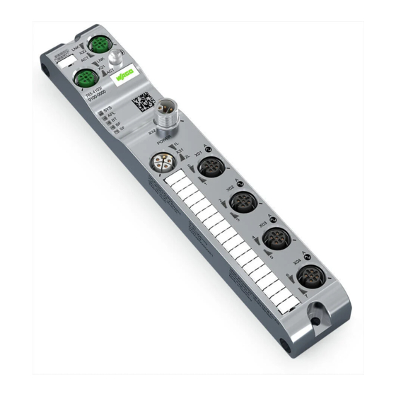
4-Port IO-Link Master Class A; EtherCAT; 24 V DC; 2.0 A; 4 x M12 Connection
Brand:
WAGO
| Category:
I/O Systems
| Size: 5.81 MB
Table of Contents
Table of Contents
3
1 Provisions
7
Document Portfolio
7
Intended Use
7
Table 1 Scope of Applicability
7
Table 2 Complete Instructions for Use
7
Typographical Conventions
8
Legal Information
10
2 Safety
11
General Safety Rules
11
Electrical Safety
11
Mechanical Safety
12
Thermal Safety
12
Indirect Safety
12
3 Overview
13
4 Properties
14
View
14
Table 3 Legend for "View" Figure
14
Connections
15
Power Supply
15
Communication Interfaces
16
ETHERNET Interfaces
16
IO-Link (Master)
16
Network Connections
16
Table 4 Supply Voltage
16
Table 5 IO-Link (Class A)
16
Table 6 ETHERNET Interfaces
16
Circuit Diagram
17
Technical Data
17
Mechanical Data
17
Product
17
Table 7 Product
17
Table 8 Mechanical Data
17
Connection Technology
18
Table 10 IO-Link Port (Class A)
18
Table 9 Connection Technology
18
Power Supply
19
Table 11 Power Supply
19
Communication
20
Electrical Safety
20
Environmental Conditions
20
Table 12 Electrical Safety
20
Table 13 Environmental Conditions
20
Table 14 Communication
20
Table 15 Ethercat® Slave
20
Table 16 OPC UA Server
21
Table 17 Communication - Bluetooth® Transmitter
21
Derating
22
Regulations and Standards
22
Approvals
22
Table 18 Standards and Regulations
22
5 Functions
24
Process Image
24
Table 19 Objects 0X1A0X: Assignment of the IO-Link Input Data
24
Table 20 Objects 0X1A0X: Assignment of the Digital Input
25
Table 21 Object 0X1A10: Assignment of the Digital Inputs
26
Table 22 Input Process Data (Port-Based Assignment)
26
Table 23 Input Process Data (Pin-Based Assignment)
26
Table 24 Object 0X1A11: Assignment of "New Message Available
26
Table 25 Object 0X1A80: Assignment of the IO-Link Port Status
27
Table 26 Object 0X160X: Assignment of the IO-Link Output Data
27
Table 27 Objects 0X160X: Assignment of the Digital Output
28
Table 28 Object 0X1610: Assignment of the Digital Outputs
28
Forcing
29
Table 29 Output Process Data (Port-Based Assignment)
29
Table 30 Output Process Data (Pin-Based Assignment)
29
Monitoring Functions
30
Overload Protection
30
Parameterization Tools
31
Overview
31
Table 31 Overview of Parameterization Tools
31
Table 32 Parameterization Overview
31
WAGO IO-Link Configurator
32
Table 33 Function Overview for WAGO I/O Field Webserver and WAGO IO-Link Modules
33
WAGO Webserver I/O Field
33
WAGO I/O Field App
34
Communication Interfaces
35
Ethercat
35
OPC UA Server
35
6 Planning
37
Structure Guidelines
37
Data Security
37
Deliberate Influences
37
Installation Site and Touch-Proof Protection
37
Random Influences
37
Table 34 Additional Documentation
37
Power Supply Concept
38
Design Power Supply
38
Table 35 Upper Limits for Current on the Individual Pins of the Connections
40
Table 36 Module 0765-4203/0100-0000 - Currents in Supply Cable 1
40
Requirements on the Power Supply
41
Table 37: Module 0765-4203/0100-0000 - Currents in Supply Cable 2
41
Table 38: Rules for Supply Cables 1 and 2
41
Additional Measures
42
Power Supply Examples
42
Settings Options
45
Module Parameters
45
Table 39 Module Parameters
45
Table 40 Port Parameters
46
Table 41 IO-Link Port Parameters
47
Table 42 Calculation of Port Cycle Time
48
7 Transport and Storage
50
8 Installation and Removal
51
Installation
51
Before Installation
51
Installation Instructions
51
Tools Required for Installation
51
After Installation
52
Grounding
52
Installation
52
Installation Distances
52
Note on Protecting against Heat Generation by the Product
52
Removal
53
After Removal
53
Before Removal
53
Tools Required for Removal
53
9 Connection
54
General Information on Installation
54
Connecting the Power Supply
54
Connecting Cables
57
Connecting the Fieldbus
57
Connect Sensors/Actuators
59
Table 43 Connecting an IO-Link Device or Digital Input or Output
61
10 Commissioning
63
Getting the IP Address from the Ethercat Master
63
Configuring Ethercat
63
Configuring a Port
64
Selecting the Module
64
Table 44 Configuration of the IO-Link Port
64
Setting Parameters
65
Parameterization
65
Call WAGO Webserver I/O Field
65
WAGO Webserver I/O Field
65
Maintenance Information
66
Table 45 Data on the "Dashboard" Page
66
User Interface of the WAGO Webserver I/O Field
66
Advanced Module and Port Information
67
Displaying Licenses
67
Displaying Port Information
67
Opening the Product Information Via WAGO Webserver I/O Field
67
Table 46 Tabs for Port Information and Settings (IO-Link Ports X01, X02 Etc.)
67
Displaying Measured Values and Information on Connected IO-Link Devices
68
Table 47 Additional Information on the Products Connected to the Selected Port
69
Displaying Port Status Information
70
State
70
Table 48 Possible Values of "State" (Port Status Information)
70
Baud Rate
71
Cycle Time
71
Quality
71
Revision ID
71
Table 49 Meaning of the Individual Bits
71
Device ID
72
Displaying Process Data
72
Input Data Length
72
Table 50 Cycle Time of the Master - Bits 6
72
Vendor ID
72
Configure Ports
73
Parameterizing the Module Via the WAGO I/O Field Webserver
73
Table 51 Port Configuration Settings for IO-Link Devices
73
Table 52 "Port Mode" Drop-Down Menu: Selecting the Operating Mode for Pin 4 of the Selected IO-Link Port
74
Table 53 IQ Behavior Drop-Down Menu - Configuration of Pin 2 (I/Q) for IO-Link Class a De- Vices
75
Table 54 Possible Values of the Inspection Level Parameter
75
Table 55 Possible Values of the Backup Level Parameter
76
Table 56 Setting the Inspection Levels and Backup Levels for Device Check During Validation and Backup
76
Accessing a Connected IO-Link Device
77
Configuring IP Parameters
80
Storing Maintenance Information
80
Table 57 Maintenance Information
81
Updating Firmware
82
Resetsetting the Module to the Factory Settings
83
Configure Bluetooth
84
Table 58 Options for Resetting the Module to the Factory Settings
84
Table 59 Status of the Last Bluetooth® Firmware Update
86
Logging Users on and off and Managing Them
87
Forcing Digital Inputs and Outputs
90
Table 60 Input Options for Forcing for each Pin of a Port
90
Forcing for IO-Link Ports
91
OPC UA Server
93
Parameterizing a Module with the WAGO I/O Field App
93
WAGO I/O Field App
93
WAGO IO-Link Configurator
93
Identifying Devices
94
Parameterizing the Product Via OPC UA
94
Table 61 Identify Devices
94
Configuring Parameters
95
Table 62 Device-Specific Configuration Parameters
95
Table 63 Port-Specific Configuration Parameters
95
Reading out Diagnostic Information
96
Reading out Measured Values
96
Table 64 Device-Specific (Calculated) Measured Values
96
Table 65 Port-Specific Measured Values
96
Reading Statistics
97
Table 66 Port-Specific Diagnostics
97
Table 67 Port Specific Statistical Information
97
11 Diagnostics
99
Diagnostics Via Indicators
99
Table 68 Supply Voltage Status, 1L and 2L
99
Table 69 System Status
99
Table 70 Field LED
99
Table 71 APL LED
99
Table 72 Ethercat® Slave Status
100
Table 73 LED States of Ethercat® Slave
100
Table 74 ETHERNET Status
100
Table 75 LED States ETHERNET Status
101
Table 76 LED States
101
Table 77 IO-Link Port Status (Class A)
101
Diagnostics Via Ethercat
102
Diagnostic History
102
Subindex 0: Highest Supported Subindex
102
Subindex 1: Maximum Messages
102
Subindex 2: Newest Message
102
Subindex 3: Newest Acknowledged Message
102
Table 78 Diagnostic History (Index 0X10F3)
102
Subindex 4: New Messages Available
103
Subindex 5: Flags
104
Subindexes 6-69: Diagnosis Message (Write-Protected)
104
Table 79 Flags for Controlling the Sending and Saving of Diagnostic Messages
104
Structure of a Diagnostic Message
105
Table 80 Structure of a Diagnostic Message in Subindexes 6 to 69
105
Emergency Error Codes
106
Table 81 Event Qualifier
106
Table 82 Emergency Error Codes
106
Table 83 General Alarms
107
Events Triggered by the IO-Link Master
108
Table 84 IO-Link Master Events
108
Events Triggered by the IO-Link Device
109
Table 85 Standard Events of the IO-Link Device
109
Diagnostic Data of the Modules
110
Table 86 Diagnostic Data of the Modules
110
Table 87 Status of the IO-Link Master
110
12 Service
111
Resetting to Factory Settings
111
Updating Firmware
111
13 Decommissioning
112
Entsorgung und Recycling
112
Table 88 WEEE Mark
112
14 Appendix
113
Installation Regulations Specified by Approvals
113
Operational Description
114
Table 89 Bluetooth® Transmitter
114
Protected Rights
115
Table 90 Temperature Range
115
Table 91 Voltage Range
115
List of Tables
117
Advertisement
Advertisement
Related Products
WAGO 767-6402
WAGO 765-1202/0100-0000
WAGO TEchDocs 765-4501/0100-0000
WAGO 765-1205/0100-0000
WAGO 765-1205/100-000
WAGO 765-1505/100-000
WAGO 765-1503/100-000
WAGO 765-4102/0100-0000
WAGO 765-1103/100-000
WAGO 7650-654/000-001
WAGO Categories
I/O Systems
Control Unit
Power Supply
Switch
Controller
More WAGO Manuals
Login
Sign In
OR
Sign in with Facebook
Sign in with Google
Upload manual
Upload from disk
Upload from URL