
Related Manuals for Cabletron Systems 2208


Summary of Contents for Cabletron Systems 2208
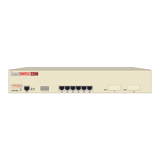
- Page 1 2H22-08R SmartSwitch 2208 User’s Guide Title Page 2H22-08R RESET 9032385-02...
-
Page 3: Fcc Notice
Only qualified personnel should perform installation procedures. Cabletron Systems reserves the right to make changes in specifications and other information contained in this document without prior notice. The reader should in all cases consult Cabletron Systems to determine whether any such changes have been made. -
Page 4: Industry Canada Notice
IMPORTANT: Before utilizing this product, carefully read this License Agreement. This document is an agreement between you, the end user, and Cabletron Systems, Inc. (“Cabletron”) that sets forth your rights and obligations with respect to the Cabletron software program (the “Program”) contained in this package. -
Page 5: United States Government Restricted Rights
Government is subject to restrictions as set forth in subparagraph (c) (1) (ii) of the Rights in Technical Data and Computer Software clause at 252.227-7013. Cabletron Systems, Inc., 35 Industrial Way, Rochester, New Hampshire 03867-0505. 2H22-08R SmartSwitch 2208 User’s Guide... -
Page 6: Safety Information
Do not use optical instruments to view the laser output. The use of optical instruments to view laser output increases eye hazard. When viewing the output optical port, power must be removed from the network adapter. SAFETY INFORMATION SAFETY INFORMATION 2H22-08R SmartSwitch 2208 User’s Guide watts. -
Page 7: Declaration Of Conformity
Mr. Ronald Fotino ___________________________________ Full Name Principal Compliance Engineer ___________________________________ Title Rochester, NH, USA ___________________________________ Location 2H22-08R SmartSwitch 2208 User’s Guide 89/336/EEC 73/23/EEC Cabletron Systems, Inc. 35 Industrial Way PO Box 5005 Rochester, NH 03867 Mr. J. Solari Cabletron Systems Limited... - Page 8 Notice 2H22-08R SmartSwitch 2208 User’s Guide...
-
Page 9: Table Of Contents
Required Tools ... 3-1 Unpacking the 2H22-08R ... 3-2 Installing Options ... 3-2 Installing the 2H22-08R ... 3-3 3.4.1 Tabletop and Shelf Installations... 3-3 3.4.2 Rackmount Installation ... 3-4 Connecting Power to the 2H22-08R... 3-6 2H22-08R SmartSwitch 2208 User’s Guide CONTENTS... - Page 10 Setting the Screen Lockout Time ...5-25 5.7.9 Setting the Operational Mode...5-26 5.7.10 Configuring the COM Port ...5-27 5.7.11 Clearing NVRAM ...5-30 SNMP Community Names Screen...5-32 5.8.1 Establishing Community Names ...5-33 SNMP Traps Screen ...5-35 5.9.1 Configuring the Trap Table...5-36 viii 2H22-08R SmartSwitch 2208 User’s Guide...
- Page 11 5.19.2 Using the Clear Counters Command ... 5-73 5.20 RMON Statistics Screen... 5-74 5.20.1 Displaying RMON Statistics ... 5-78 5.20.2 Using the Clear Counters Command ... 5-78 5.21 Network Tools... 5-79 5.21.1 Built-in Commands ... 5-81 5.21.2 Special Commands... 5-92 2H22-08R SmartSwitch 2208 User’s Guide CONTENTS...
- Page 12 FE-100F3 ... B-3 APPENDIX C OPTIONAL INSTALLATIONS AND MODE SWITCH BANK SETTINGS Required Tools... C-1 Removing the Chassis Cover ... C-2 C.2.1 Setting the Mode Switch ... C-5 Installing Optional Fast Ethernet Interface Modules ... C-7 INDEX 2H22-08R SmartSwitch 2208 User’s Guide...
-
Page 13: Chapter 1 Introduction
Welcome to the Cabletron Systems 2H22-08R SmartSwitch 2208 User’s Guide. This guide provides the necessary documentation to install and operate the 2H22-08R SmartSwitch 2208 standalone device and provides information concerning network requirements, installation, troubleshooting, and the use of Local Management. - Page 14 FE-100FX and FE100-F3. Appendix Optional Installations and Mode Switch Bank describes how to install optional Fast Ethernet Interface Modules and how to set the mode switches. Page 1-2 2H22-08R SmartSwitch 2208 User’s Guide Specifications, Settings,...
-
Page 15: 2H22-08R Overview
2H22-08R RESET The 2H22-08R supports traditional IEEE 802.1d switching (bridging), IEEE 802.Q switching, and Cabletron Systems S Virtual Network technology. The 2H22-08R is used to connect individual high-bandwidth user devices, such as workstations, and provide a central switching point for multiple 10/100 Mbps Fast Ethernet segments. -
Page 16: Connectivity
At this point, the interval remains at 300 seconds. The RAD requests continue until an IP address is received from a BootP server, or an IP address is entered using Local Management. Page 1-4 2H22-08R SmartSwitch 2208 User’s Guide... -
Page 17: Remote Monitoring (Rmon)
MIBs including RFC 1213 (MIB II), RFC 1757 (RMON), RFC 1493 (Bridge MIB), and RFC 1354 (FIB MIB). A full suite of Cabletron Systems Enterprise MIBs provides a wide array of statistical information to enhance troubleshooting. -
Page 18: Local Management
Any broadcast frames above this specified limit are dropped. In the event that broadcast frames are being suppressed, multicast and unicast frames continue to be switched without suppression. Page 1-6 Section 1.4.1 2H22-08R SmartSwitch 2208 User’s Guide through... -
Page 19: Port Redirect Function
flexibility. SmartTrunking on the 2H22-08R is available to group the optional Fast Ethernet Interface Module ports 7 and 8. For more information about SmartTrunk, refer to the Cabletron Systems SmartTrunk User’s Guide. 2H22-08R SmartSwitch 2208 User’s Guide Local Management... -
Page 20: Optional Features
Uses SC FE-100F3 connector Page 1-8 1-1. Application Supports Category 5 Unshielded Twisted Pair (UTP) cabling, which has an impedance of 85 to 111 ohms. Supports multimode fiber optic cabling. Supports single mode fiber optic cabling. 2H22-08R SmartSwitch 2208 User’s Guide... -
Page 21: Document Conventions
In Local Management sections, Bold type indicates fields, field values, and commands that can be highlighted or selected by the user. In Local Management sections, keystrokes are shown in UPPERCASE. Italic type denotes complete book titles. 2H22-08R SmartSwitch 2208 User’s Guide Document Conventions Page 1-9... -
Page 22: Getting Help
Cabletron Systems Technical Writing Department via the following email address: TechWriting@cabletron.com Make sure to include the document Part Number in the email message. Before calling the Cabletron Systems Global Call Center, have the following information ready: • Your Cabletron Systems service contract number •... -
Page 23: Related Manuals
These manuals can be obtained from the World Wide Web in Adobe Acrobat Portable Document Format (PDF) at the following site: http://www.cabletron.com/ All documentation for the Cabletron Systems SecureFast VLAN NOTE Manager software is contained on the VLAN Manager CD-ROM. The documentation for the HSIM-W6 and HSIM-W84 is on the QuickSET CD-ROM. - Page 24 Chapter 1: Introduction Page 1-12 2H22-08R SmartSwitch 2208 User’s Guide...
-
Page 25: Chapter 2 Network Requirements
Failure to follow these guidelines may produce poor network performance. The Cabletron Systems Cabling Guide and SmartTrunk User’s NOTE Guide, referred to in the following sections, are found on the Cabletron Systems World Wide Web site: http://www.cabletron.com/... -
Page 26: 100Base-Tx Network
100BASE-FX FIBER OPTIC NETWORK Ports 7 and 8 of the 2H22-08R support the Cabletron Systems FE-100FX and FE-100F3 fiber optic interface modules. The device at the other end of the fiber optic segment must meet the 100BASE-FX Fast Ethernet network requirements to operate at 100 Mbps. -
Page 27: Chapter 3 Installation
Installing the 2H22-08R (on a shelf or tabletop, or into a standard rack) (Section 3.4) • Connecting to the Network • Completing the Installation REQUIRED TOOLS A Phillips screwdriver is required to install the 2H22-08R in a rack. 2H22-08R SmartSwitch 2208 User’s Guide CHAPTER 3 INSTALLATION 3.1) (Section 3.2) (Section 3.3) (Section 3.6) -
Page 28: Unpacking The 2H22-08R
Install any optional equipment before proceeding to NOTE Section 3.4. If the 2H22-08R is to be installed with an optional Fast Ethernet Interface Module, refer to Appendix C Page 3-2 Table Section for installation instructions. 2H22-08R SmartSwitch 2208 User’s Guide 3-1. Quantity 1.7. -
Page 29: Installing The 2H22-08R
B = 45 cm (22.5 in) C = 53 cm (21 in) D = 213 cm (7 ft) Figure 3-1 Tabletop or Shelf Installation 2H22-08R SmartSwitch 2208 User’s Guide provides the rules and instructions for a Installing the 2H22-08R Figure 3-1... -
Page 30: Rackmount Installation
CAUTION 2H22-08R. Use of longer screws may damage the unit. Attach the strain-relief bracket to the bottom of the 2H22-08R using the four 8-32 x 3/8-inch pan-head screws Page 3-4 (Figure 2H22-08R SmartSwitch 2208 User’s Guide Figure 3-1 Appendix 3-2). - Page 31 With the mounting brackets installed, position the 2H22-08R between the vertical frame members of the 19-inch rack and fasten it securely with user supplied mounting screws as shown in 2H22-08R SmartSwitch 2208 User’s Guide Screws (4) 6 5 4 3 Figure 3-3.
-
Page 32: Connecting Power To The 2H22-08R
The POWER LED turns on (green) and the CPU LED turns on (green) briefly. Figure 3-5 2H22-08R Rear View Page 3-6 19-Inch Rack Screws (4) Figure 3-5. To take advantage of the load 2H22-08R SmartSwitch 2208 User’s Guide 2251-03 Primary Redundant 1960-62... -
Page 33: Connecting To The Network
Check the power cord connections and the power source. If there are no problems with the power cord connections or power source and the PWR LED is still not green, contact the Cabletron Systems Global Call Center. Refer to Section 1.7 for details. -
Page 34: Connecting A Twisted Pair Segment To The Fe-100Tx
7. NC 4. NC 8. NC Figure 3-6 FE-100TX Crossover Switch A schematic of a crossover cable is shown in not cross over, use the switch on the FE-100TX to internally cross over the RJ45 port. RJ45 Port RX– TX–... - Page 35 Verify that the RJ45 connector on the twisted pair segment has the proper pinouts. Check the cable for continuity. 2H22-08R SmartSwitch 2208 User’s Guide Figure 1 0 0 F E - 1 0 0 T...
-
Page 36: Connecting A Fiber Optic Segment To The Fe-100Fx And Fe-100F3
FE-100FX and FE-100F3 The FE-100FX and FE-100F3 have SC style network ports. See Figure 3-9. Cabletron Systems offers optional fiber optic cables that use SC style connectors. The ST connectors are keyed to ensure proper crossover of the transmit and receive fibers. - Page 37 2H22-08R. See At the other end of the fiber optic cable, attach the SC connector to the other device. Figure 3-9 FE-100FX and FE-100F3 Ports 2H22-08R SmartSwitch 2208 User’s Guide Connecting to the Network Figure 3-9. TX LED...
-
Page 38: Completing The Installation
Verify that the fiber connection meets the dB loss specifications outlined in Section If a link has not been established, contact the Cabletron Systems Global Call Center. Refer to Section 1.7 COMPLETING THE INSTALLATION... -
Page 39: Chapter 4 Troubleshooting
Troubleshooting network and 2H22-08R operational problems • Using the RESET button USING LANVIEW The 2H22-08R uses Cabletron Systems built-in visual diagnostic and status monitoring system called LANVIEW. The LANVIEW LEDs (Figure 4-1) allow quick observation of the network status to aid in the diagnosing of network problems. - Page 40 Should flash green every 2 seconds indicating BPDUs being sent if STA is enabled and there is a valid link. No action. Port may be disabled due to Spanning Tree. No action. Contact Cabletron Systems GCC for assistance. 2H22-08R SmartSwitch 2208 User’s Guide...
-
Page 41: Fe-100Tx Led
NOTE LED is on. No Link exists if the associated port (port 7 or 8) Receive (RX) LED is off. 2H22-08R SmartSwitch 2208 User’s Guide Explanation No link or no cable attached. There is a link and the port is operating at 10 Mbps operation. -
Page 42: Troubleshooting Checklist
Refer to for Community Names Table setup. Refer to address assignment procedure. Enable port. Check link to device. 2H22-08R SmartSwitch 2208 User’s Guide for a checklist Chapter 5 Appendix A Chapter 5 Chapter 5 for IP... - Page 43 RESET button is Clear NVRAM was set pressed. through Local Management. 2H22-08R SmartSwitch 2208 User’s Guide Troubleshooting Checklist Recommended Action Review network design and delete unnecessary loops. Reenter the lost parameters as necessary. Call...
-
Page 44: Using The Reset Button
The device processor goes through a reset process of approximately 20 seconds. Additional downtime may be added as the 2H22-08R reenters the network. Page 4-6 Section 5.7.11, Clearing NVRAM, describes how 2H22-08R RESET Reset Button Figure 4-3 RESET Button 2H22-08R SmartSwitch 2208 User’s Guide Appendix C, to clear... -
Page 45: Chapter 5 Local Management
Locally using a VT type terminal connected to the COM port of the 2H22-08R • Remotely using a VT type terminal connected through a modem • In-band through a Telnet connection 2H22-08R SmartSwitch 2208 User’s Guide CHAPTER 5 Page 5-1... -
Page 46: Local Management Keyboard Conventions
Management increment field. For example, “Press [–]” means to press the minus sign key. The DEL (Delete) key removes characters from a Local Management field. For example, “Press DEL” means to press the Delete key. 2H22-08R SmartSwitch 2208 User’s Guide Table 5-1 explains... -
Page 47: Management Terminal Setup
A VT type terminal running emulation programs for the Digital Equipment Corporation VT100 series • A remote VT100 type terminal via a modem connection • In-Band via a Telnet connection 2H22-08R SmartSwitch 2208 User’s Guide Management Terminal Setup Page 5-3... -
Page 48: Console Cable Connection
Connect the RJ45-to-DB9 adapter to the communications port on the PC. 2H22-08R RESET Figure 5-1 Management Terminal Connection (PC Connection) Page 5-4 RJ45 COM Port RJ45-to-DB9 PC Adapter 2H22-08R SmartSwitch 2208 User’s Guide Figure UTP Cable with RJ45 Connectors 5-1. -
Page 49: Uninterruptible Power Supply Monitoring
Connect the RJ45 connector at one end of the cable to the COM port on the 2H22-08R. Plug the RJ45 connector at the other end of the cable into the RJ45-to-DB9 male (UPS) adapter, Cabletron Systems Part No. 9372066. Connect the RJ45-to-DB9 male (UPS) adapter to the female DB9 port on the rear of the UPS device (refer to the particular UPS device’s user... -
Page 50: Management Terminal Setup Parameters
2400, 4800, 9600, 19200 Receive=Transmit XOFF at 64 8 bits No Parity 1 Stop Bit No Local Echo DEC-423, Data Leads Only Limited Transmit No Auto Answerback Typewriter Keys any option any option Margin Bell Warning Bell 2H22-08R SmartSwitch 2208 User’s Guide... -
Page 51: Telnet Connections
For information about setting the IP address, refer to Section 5.7. For information about assigning Community Names, refer to Section 5.8. Refer to the instructions included with the Telnet application for information about establishing a Telnet session. 2H22-08R SmartSwitch 2208 User’s Guide Page 5-7... -
Page 52: Accessing Local Management
Figure 2H22-08R LOCAL MANAGEMENT CABLETRON Systems, Incorporated P.O.Box 5005 Rochester, NH 03866-5005 USA (603) 332-9400 (c) Copyright CABLETRON Systems, Inc, 1997 Device Serial Number: Device Hardware Revision: Device Firmware Revision: Device BOOTPROM Revision: Enter Password: 2H22-08R SmartSwitch 2208 User’s Guide 5-3. -
Page 53: Navigating Local Management Screens
802.1d Switching (traditional switching) • 802.1Q Switching (802.1Q port based switching) • SECURE FAST VLAN (Cabletron Systems SecureFast switching) Depending on the Operational Mode set for the device, the hierarchy of Local Management screens differs as shown in Figure 5-6. Refer to the appropriate figure that relates to the Operational Mode set for the device to see the applicable Local Management screen hierarchy. - Page 54 Ethernet Interface Configuration Device Specific Configuration Menu Device Statistics Interface Statistics Menu RMON Statistics Network Tools 2H22-08R SmartSwitch 2208 User’s Guide System Resources Flash Download Port Redirect Function Broadcast Supression 802.1Q VLAN Configuration System Resources Flash Download 802.1Q VLAN Configuration...
-
Page 55: Selecting Local Management Menu Screen Items
To end the LM session, use the arrow keys to highlight the RETURN command at the bottom of the Device Menu screen. Press ENTER. The Local Management Password screen displays and the session ends. 2H22-08R SmartSwitch 2208 User’s Guide Accessing Local Management Page 5-11... -
Page 56: Device Menu Screen
Section Page 5-12 Figure 5-7, is the access point for all 2H22-08R LOCAL MANAGEMENT Device Menu DEVICE CONFIGURATION DEVICE STATISTICS NETWORK TOOLS EXIT 5.12. 2H22-08R SmartSwitch 2208 User’s Guide Firmware Revision: XX.XX.XX BOOTPROM Revision: XX.XX.XX RETURN 2251_13... -
Page 57: Device Statistics
NETWORK TOOLS The Network Tools function resides on the 2H22-08R and consists of a series of commands that allow you to access and manage network devices. Section 5.21 explains using the Network Tools utility. 2H22-08R SmartSwitch 2208 User’s Guide Page 5-13... -
Page 58: Device Configuration Menu Screen
2H22-08R LOCAL MANAGEMENT Device Configuration Menu Firmware Revision: BOOTPROM Revision: XX.XX.XX GENERAL CONFIGURATION SNMP COMMUNITY NAMES SNMP TRAPS SWITCH CONFIGURATION ETHERNET INTERFACE CONFIGURATION SMARTTRUNK CONFIGURATION DEVICE SPECIFIC CONFIGURATION EXIT 2H22-08R SmartSwitch 2208 User’s Guide 5-8, provides access to XX.XX.XX RETURN 2251_66... - Page 59 The SmartTrunk Configuration screen allows the user to logically group interfaces together to aggregate high speed uplinks. Refer to the Cabletron Systems SmartTrunk User’s Guide for additional information. DEVICE SPECIFIC CONFIGURATION The Device Specific Configuration menu screen allows you to select screens to configure ports or check system resources specific to the...
-
Page 60: General Configuration Screen
00-00-ID-00-00-00 Device Date: 000.000.000.000 Device Time: 255.255.0.0 Screen Refresh Time: NONE DEFINED Screen Lockout Time: Device Uptime XX D XX H XX M 0.0.0.0 [LM] EXIT 2H22-08R SmartSwitch 2208 User’s Guide XX.XX.XX 10/11/1997 14:23:00 30 sec. 15 min. RETURN 2159-16... - Page 61 Screen Refresh Time (Modifiable) Contains the rate at which the screens are updated. This setting determines how frequently (in seconds) information is updated on the screen. To enter a new update time, refer to Section 5.7.7. 2H22-08R SmartSwitch 2208 User’s Guide Page 5-17...
- Page 62 This field allows the user to set the 2H22-08R to operate as a traditional switch (802.1d SWITCHING option), an IEEE 802.1Q switch (802.1Q SWITCHING option), or as a Cabletron Systems SecureFast switch (SECURE FAST VLAN option). In 802.1d SWITCHING mode, the six ports located on the front panel, and each Fast Ethernet Interface Module are bridged to each other.
-
Page 63: Setting The Ip Address
ENTERED”. Local Management does not alter the current value and refreshes the IP address field with the previous value. Use the arrow keys to highlight the SAVE command, then press ENTER. The warning screen shown in 2H22-08R SmartSwitch 2208 User’s Guide General Configuration Screen 5.7.11. Figure 5-10 displays. -
Page 64: Setting The Subnet Mask
To change the subnet mask from its default, perform the following steps: Use the arrow keys to highlight the Subnet Mask field. Enter the subnet mask into this field using Decimal Dotted Notation (DDN) format. For example: 255.255.255.0 Page 5-20 WARNING! 2H22-08R SmartSwitch 2208 User’s Guide 174252... - Page 65 ARE YOU SURE YOU WANT TO CONTINUE? Figure 5-11 Configuration Warning Screen Use the arrow keys to highlight the YES command and press ENTER. The changes are saved and the module reboots. 2H22-08R SmartSwitch 2208 User’s Guide General Configuration Screen Figure 5-10 WARNING! displays.
-
Page 66: Setting The Default Gateway
Default Gateway field with the previous value. Use the arrow keys to highlight the SAVE command. Press ENTER. The message “SAVED OK” displays at the top of the screen. Page 5-22 2H22-08R SmartSwitch 2208 User’s Guide... -
Page 67: Setting The Tftp Gateway Ip Address
Local Management refreshes the TFTP Gateway IP Address field with the previous value. Use the arrow keys to highlight the SAVE command. Press ENTER. The Event Message Line at the top of the screen displays “SAVED OK”. 2H22-08R SmartSwitch 2208 User’s Guide General Configuration Screen Page 5-23... -
Page 68: Setting The Device Date
Press ENTER to set the system clock to the time in the input field. Use the arrow keys to highlight the SAVE command at the bottom of the screen and press ENTER. Page 5-24 ., type “064500” in the Device Time field. 2H22-08R SmartSwitch 2208 User’s Guide... -
Page 69: Entering A New Screen Refresh Time
“SAVED OK” displays at the top of the screen. If the entry is not valid, Local Management does not alter the current setting, but it does refresh the Screen Lockout Time field with the previous value. 2H22-08R SmartSwitch 2208 User’s Guide General Configuration Screen Page 5-25... -
Page 70: Setting The Operational Mode
Chapter 5: Local Management 5.7.9 Setting the Operational Mode If the device is configured to operate as a SecureFast switch, it must be assign and save a unique IP address (i.e., the device CAUTION has rebooted and the new IP address is active) before setting the operational mode. -
Page 71: Configuring The Com Port
The 2H22-08R COM port supports the following applications: • Local Management connections • American Power Conversion Uninterruptible Power Supply (UPS) connections Use the arrow keys to highlight the Com field. 2H22-08R SmartSwitch 2208 User’s Guide General Configuration Screen Page 5-27... - Page 72 If the COM port is reconfigured without a valid IP address set on the device, the message shown in CAUTION Do not continue unless the outcome of the action is fully understood. Page 5-28 Section 5.7.11) to reestablish COM port Figure 5-13 2H22-08R SmartSwitch 2208 User’s Guide displays.
- Page 73 Use the arrows keys to highlight the Application field. Use the SPACE bar or BACKSPACE to step through the available settings until the operation you require displays. available settings and their corresponding applications. 2H22-08R SmartSwitch 2208 User’s Guide General Configuration Screen WARNING Table 5-3...
-
Page 74: Clearing Nvram
Use the SPACE bar to toggle the field to YES. Use the arrow keys to highlight SAVE at the bottom of the screen. Press ENTER. The warning shown in Page 5-30 Application Local Management Session APC Power Supply SNMP Proxy Figure 5-14 2H22-08R SmartSwitch 2208 User’s Guide displays. - Page 75 Figure 5-14 Clear NVRAM Warning Screen Select YES and the message “CLEARING NVRAM. REBOOT IN PROGRESS...” displays. The 2H22-08R clears NVRAM and reboots. All user-entered parameters default to factory settings. 2H22-08R SmartSwitch 2208 User’s Guide General Configuration Screen WARNING 174251 Page 5-31...
-
Page 76: Snmp Community Names Screen
Figure 5-15 SNMP Community Names Screen Page 5-32 Figure 2H22-08R LOCAL MANAGEMENT SNMP Community Names Community Name Access Policy public read-only public read-write public super-user EXIT 2H22-08R SmartSwitch 2208 User’s Guide 5-15, displays. Firmware Revision: XX.XX.XX BOOTPROM Revision: XX.XX.XX RETURN 2159-17... -
Page 77: Establishing Community Names
Names screen is a password to its corresponding level of access to Local Management. The community name assigned super-user access is the only one that gives the user complete access to Local Management. 2H22-08R SmartSwitch 2208 User’s Guide SNMP Community Names Screen 5.8.1. This Community Name gives you read-only access to the 2H22-08R MIB objects, and excludes access to security-protected fields of... - Page 78 The Community Names are saved to memory and their access modes implemented. Exiting without saving causes a “NOT SAVED?” message to NOTE display above the SAVE command. Edits are lost if they are not saved before exiting. Page 5-34 2H22-08R SmartSwitch 2208 User’s Guide...
-
Page 79: Snmp Traps Screen
Trap Destination 0.0.0.0 0.0.0.0 0.0.0.0 0.0.0.0 0.0.0.0 0.0.0.0 0.0.0.0 0.0.0.0 SAVE Figure 5-16 SNMP Traps Screen 2H22-08R SmartSwitch 2208 User’s Guide Figure 5-16. 2H22-08R LOCAL MANAGEMENT SNMP Traps Firmware Revision: BOOTPROM Revision: XX.XX.XX Trap Community Name public public public public... -
Page 80: Configuring The Trap Table
SPACE bar to choose either YES (send alarms from the 2H22-08R to the workstation), or NO (prevent alarms from being sent). Use the arrow keys to highlight the SAVE command and press ENTER. The message “SAVED OK” displays. Page 5-36 Section 5.9.1. 2H22-08R SmartSwitch 2208 User’s Guide Section 5.9.1. -
Page 81: Switch Configuration Screen
Menu screen, use the arrow keys to highlight the SWITCH CONFIGURATION menu item and press ENTER. The Switch Configuration screen displays showing Ports 1 through 8. 2H22-08R SmartSwitch 2208 User’s Guide Switch Configuration Screen Figure 5-17, provides the basic setup... - Page 82 Switch Configuration Firmware Revision: BOOTPROM Revision: XX.XX.XX Type of STA: Age Time (sec): State forwarding listening standby learning listening forwarding listening listening EXIT 2H22-08R SmartSwitch 2208 User’s Guide XX.XX.XX [DEC] Status [ENABLED] [DISABLED] [ENABLED] [DISABLED] [ENABLED] [DISABLED] [ENABLED] [DISABLED] RETURN 2159-19...
- Page 83 Displays the total number of switched ports. Type of STA (Toggle) Allows you to set the method that switches use to decide which switch is the controlling (Root) switch when two or more switches exist in parallel (Spanning Tree Algorithm). Valid entries include IEEE, DEC, and None.
-
Page 84: Setting The Sta
5.10.1 Setting the STA The Spanning Tree Algorithm (STA) setting allows you to set the method that the switches use to decide which is the controller (Root) switch when two or more switches are in parallel. The available selections are IEEE, DEC, and NONE. -
Page 85: Setting The Age Time
2. Use the SPACE bar to toggle to either ENABLED or DISABLED. 3. Use the arrow keys to highlight the SAVE command at the bottom of the screen. 4. Press ENTER. The message “SAVED OK” displays. 2H22-08R SmartSwitch 2208 User’s Guide Switch Configuration Screen Page 5-41... -
Page 86: Ethernet Interface Configuration
[Auto-Neg] 10Base-TFD [100Base-TXFD] 100Base-TXFD [100Base-TXFD] 100Base-TXFD [100Base-TXFD] 100Base-TX [100Base-TXFD] 10Base-T [100Base-TX] 100Base-FXFD [100Base-FXFD] 100Base-FX [100Base-FX] [ Enabled ] 2H22-08R SmartSwitch 2208 User’s Guide XX.XX.XX Advertised Ability [100Base-TXFD] [Disabled] [100Base-TXFD] [Enabled] [100Base-TXFD] [Enabled] [100Base-TXFD] [Enabled] [100Base-TXFD] [Disabled] [100Base-TX] [Enabled] EXIT RETURN... - Page 87 However, Local Management allows you to optionally configure that port. 2H22-08R SmartSwitch 2208 User’s Guide Ethernet Interface Configuration Section 5.11.1 describes how to configure an Section 5.11.4...
-
Page 88: Configuring An Fe-100Tx Interface
Flow Control Admin Status (Selectable) This setting controls whether or not the switch will send a jam out all ports when there is too much traffic for the switch to process. The jam will clear the ports and enable the switch to process the current frame information. -
Page 89: Setting The Fe-100Tx Operational Mode
Enabled/Disabled field to the right of the selection. Use the SPACE bar to select Enabled or Disabled. Press ENTER. Continue this process until you have completed enabling or disabling the advertised modes. 2H22-08R SmartSwitch 2208 User’s Guide Ethernet Interface Configuration Page 5-45... -
Page 90: Configuring An Fe-100Fx Or Fe-100F3
Press ENTER. The port now operates in the chosen mode. Use the arrow keys to highlight the SAVE command. Press ENTER. The message “SAVED OK” displays and Local Management saves the changes to memory. Page 5-46 Section 5.11.5 provides instructions for 2H22-08R SmartSwitch 2208 User’s Guide... -
Page 91: Setting The Flow Control Admin Status
Use the SPACE bar to toggle the field to the desired setting. Press ENTER. Use the arrow keys to highlight the SAVE command. Press ENTER. The message “SAVED OK” displays and Local Management saves the changes to memory. 2H22-08R SmartSwitch 2208 User’s Guide Ethernet Interface Configuration Page 5-47... -
Page 92: Device Specific Configuration Menu
2H22-08R LOCAL MANAGEMENT Device Specific Configuration Menu Firmware Revision: BOOTPROM Revision: XX.XX.XX SYSTEM RESOURCES FLASH DOWNLOAD PORT REDIRECT FUNCTION BROADCAST SUPPRESSION 802.1Q VLAN CONFIGURATION EXIT 2H22-08R SmartSwitch 2208 User’s Guide Figure 5-19, XX.XX.XX RETURN 2159-21... - Page 93 Section 5.14. PORT REDIRECT FUNCTION The Port Redirect Function screen allows you to redirect traffic from one or multiple ports to a specific destination switch port. For details refer to Section 5.15. BROADCAST SUPPRESSION The Broadcast Suppression screen allows you to set a desired limit of receive broadcast frames that is forwarded per port per second.
-
Page 94: System Resources Screen
CPU Type: i960 HT 25Mhz Available: Available: XX MB Available: XX KB Current Switch Utilization: 66% Peak Switch Utilization: 75% Reset Peak Switch Utilization: [NO] EXIT 2H22-08R SmartSwitch 2208 User’s Guide XX.XX.XX XXXXX Bytes XXXXX Bytes XXXXX Bytes RETURN RETURN 2159-40... -
Page 95: Setting The Reset Peak Utilization
Shows the peak percentage of device’s switching capacity used, since the last reset. Reset Peak Switch Utilization (Toggle) Allows you to reset the Peak Switch Utilization field. The switch may be set to either YES or NO as described in Peak Switch Utilization field to the current system traffic. -
Page 96: Flash Download Screen
TFTP server. For information on how to setup a workstation as a TFTP NOTE server, refer to the specific workstation documentation. Page 5-52 Figure 5-21, allows you to upgrade Setting the Mode Switch, for details. 2H22-08R SmartSwitch 2208 User’s Guide... - Page 97 EXECUTE Figure 5-21 Flash Download Screen Download Server IP and Download Server File Name displays NOTE only when TFTP or RUNTIME are selected in Download Method. 2H22-08R SmartSwitch 2208 User’s Guide 2H22-08R LOCAL MANAGEMENT Flash Download Download Method: [TFTP] [YES] 134.141.79.123...
- Page 98 If TFTP or RUNTIME are selected as the download method (see Figure 5-21), the following two additional fields display: Download Server IP (Selectable) Enter the IP address of the TFTP server to be used for the FLASH download. Page 5-54 2H22-08R SmartSwitch 2208 User’s Guide...
-
Page 99: Image File Download Using Bootp
Use the arrow keys to highlight the Download Server IP field. Enter the IP address of the TFTP server using the DDN format. For example: 134.141.79.121 Use the arrow keys to highlight the Download File Name field. 2H22-08R SmartSwitch 2208 User’s Guide Flash Download Screen Page 5-55... -
Page 100: Image File Download Using Runtime
Enter the complete pathway and file name of the image stored on the download server. For example: /tftpboot/2H22.fls Use the arrow keys to highlight EXECUTE at the bottom of the screen and press ENTER. The message “RUNTIME DOWNLOAD. WILL Page 5-56 2H22-08R SmartSwitch 2208 User’s Guide... -
Page 101: Port Redirect Function Screen
Although all traffic from the source port (including, if desired, NOTE error frames) is sent to the destination port, normal switching is still performed for all frames on the source port. 2H22-08R SmartSwitch 2208 User’s Guide Port Redirect Function Screen Section 5.7.9,... - Page 102 Page 5-58 2H22-08R LOCAL MANAGEMENT Port Redirect Function Firmware Revision: BOOTPROM Revision: XX.XX.XX Destination Port: Remap Errors: ============ ============ Destination Port [1] Errors [ON] PREVIOUS NEXT Section 2H22-08R SmartSwitch 2208 User’s Guide XX.XX.XX Status [ADD] RETURN RETURN EXIT 1960_22 5.15.3.
-
Page 103: Displaying The Source And Destination Entries
ENTER and the next screen of entries is displayed. To display the previous screen, use the arrow keys to highlight PREVIOUS. Press ENTER to view the entries in the previous screen. 2H22-08R SmartSwitch 2208 User’s Guide Port Redirect Function Screen Section 5.15.2... -
Page 104: Changing Source And Destination Ports
Use the arrow keys to highlight SAVE at the bottom of the screen. Press ENTER. The message “SAVED OK” displays. This saves the new settings and updates the Source Interface and Destination Interface read-only fields. Page 5-60 2H22-08R SmartSwitch 2208 User’s Guide... -
Page 105: Changing The Remap Errors Field
Use the arrow keys to highlight the [ON] selection, next to the Errors field at the bottom of the screen, and press ENTER. Use the arrow keys to highlight the SAVE command and press ENTER. The changes are saved to memory. 2H22-08R SmartSwitch 2208 User’s Guide Port Redirect Function Screen Page 5-61... -
Page 106: Broadcast Suppression Screen
150000 999:23:59 150000 999:23:59 150000 999:23:59 150000 999:23:59 150000 999:23:59 150000 999:23:59 150000 999:23:59 150000 999:23:59 2H22-08R SmartSwitch 2208 User’s Guide Firmware Revision: XX.XX.XX BOOTPROM Revision: XX.XX.XX Threshold Reset Peak 150000 [NO] 150000 [NO] 150000 [NO] 150000 [NO] 150000 [NO]... -
Page 107: Setting The Threshold
(for example; 10, 20, 30, etc.). Use the arrow keys to highlight the SAVE command at the bottom of the screen. Press ENTER. The message “SAVED OK” displays. 2H22-08R SmartSwitch 2208 User’s Guide Broadcast Suppression Screen Section 5.16.2. -
Page 108: Setting The Reset Peak
Press the SPACE bar to select YES or NO. Use the arrows keys to highlight the SAVE command at the bottom of the screen. Press ENTER. The message “SAVED OK” displays and the Time Since Peak field is also reset. Page 5-64 2H22-08R SmartSwitch 2208 User’s Guide... -
Page 109: Device Statistics Menu Screen
Section 5.7.9 mode. The Device Statistics Menu screen, screens that allow you to obtain switch statistics about frame traffic through each interface and view operating statistics about each port. To access the Device Statistics Menu from the Device Menu screen, use the arrow keys to highlight the DEVICE STATISTICS menu item and press ENTER. -
Page 110: Switch Statistics
The Interface Statistics screen provides the MIB-II statistics for each switched interface, on an interface-by-interface basis. RMON STATISTICS The RMON Statistics screen displays all the statistics gathered by the embedded RMON agent built into the 2H22-08R. Page 5-66 2H22-08R SmartSwitch 2208 User’s Guide... -
Page 111: Switch Statistics Screen
VLAN. This screen may only be used by devices configured to operate as traditional or 802.1Q switches. To access the Switch Statistics screen from the Device Statistics Menu screen, use the arrow keys to highlight the SWITCH STATISTICS menu item and press ENTER. The Switch Statistics screen displays. - Page 112 This command clears all the counters of the ports displayed to zero. To clear the counters, use the arrow keys to highlight CLEAR COUNTERS at the bottom of the screen, then press ENTER. Page 5-68 2H22-08R SmartSwitch 2208 User’s Guide...
-
Page 113: Interface Statistics Screen
InDiscards: InErrors: InUnknownProtos: OutOctets: OutUnicast: OutNonUnicast: OutDiscards: OutErrors: OutQLen: Interface: [XX] Figure 5-26 Interface Statistics Screen 2H22-08R SmartSwitch 2208 User’s Guide 2H22-08R LOCAL MANAGEMENT Interface Statistics Name: Ethernet Frontpanel 7500456 Address: 6789 Last Change: Admin Status: Oper Status: MTU: Speed:... - Page 114 The InDiscards field displays the total number of inbound packets that were discarded, even though the packets contained no errors. This field may increment because the switch needed to free up buffer space, or the switch was being overutilized. InErrors (Read-only) This field displays the total number of inbound packets that have been...
- Page 115 The OutDiscards field displays the total number of outbound packets that were discarded, even though the packets contained no errors. This field may increment, because the switch needed to free up buffer space, or the switch was being overutilized. OutErrors (Read-only) This field displays the total number of outbound packets discarded...
-
Page 116: Displaying Interface Statistics
Press the SPACE bar to increment (or press the DEL (delete) key to decrement) the interface number. Press ENTER (neither the Interface # fields nor the statistics will change until ENTER is pressed). Page 5-72 Section 5.19.2. 2H22-08R SmartSwitch 2208 User’s Guide Section 5.19.1. -
Page 117: Using The Clear Counters Command
To reset all the statistics counters of the selected interface to zero, perform the following steps: Use the arrow keys to highlight the CLEAR COUNTERS command. Press ENTER, the counters for the selected interface are reset to zero. 2H22-08R SmartSwitch 2208 User’s Guide Interface Statistics Screen Page 5-73... -
Page 118: Rmon Statistics Screen
BOOTPROM Revision: XX.XX.XX Owner: monitor Status: valid Total Packets: Total Octets: 64 Octets: 127 Octets: - 255 Octets: - 511 Octets: - 1023 Octets: 1024 - 1518 Octets: CLEAR COUNTERS 2H22-08R SmartSwitch 2208 User’s Guide Figure 5-27. XX.XX.XX EXIT RETURN 2251_65... - Page 119 Drop Events (Read-only) This field displays the total number of times that the RMON agent was forced to discard packets due to the lack of available switch resources. The Drop Events field does not display the number of packets NOTE dropped, it only displays the number of times that the RMON agent was forced to discard packets.
- Page 120 FCS or a bad CRC. Total Packets (Read-only) This field displays the total number of packets (including bad packets, broadcast packets, and multicast packets) received on this interface. Page 5-76 2H22-08R SmartSwitch 2208 User’s Guide...
- Page 121 Section 5.20.1. CLEAR COUNTERS (Command) This command is used to reset all statistic counters to zero. For details on how to use this field, refer to Section 5.20.2. 2H22-08R SmartSwitch 2208 User’s Guide Page 5-77...
-
Page 122: Displaying Rmon Statistics
To reset all the statistics counters of the selected interface to zero, perform the following steps: Use the arrow keys to highlight the CLEAR COUNTERS field. Press ENTER, the counters for the selected index are reset to zero. Page 5-78 2H22-08R SmartSwitch 2208 User’s Guide... -
Page 123: Network Tools
The Network Tools functions are performed using a series of commands. Entering commands in Network Tools involves typing the command to be executed at the Network Tools prompt, adding any desired or required extensions, and pressing ENTER. 2H22-08R SmartSwitch 2208 User’s Guide Figure 5-28 defroute reset... - Page 124 Briefly describes the command and its uses. Lists any additional fields in the appropriate format which may be added to the command. Shows an example of the command. 2H22-08R SmartSwitch 2208 User’s Guide...
-
Page 125: Built-In Commands
Description: You can specify the arp command without options, or with one of the following options: Options: 2H22-08R SmartSwitch 2208 User’s Guide arp <options> The arp command provides access to the ARP (Address Resolution Protocol) cache, enabling you to view cache data, delete entries, or add a static route. - Page 126 Specifying a single interface number will affect the bridging status of that interface, while specifying ALL will affect every interface. [ENABLE/DISABLE] [IFNUM/ALL] 2H22-08R SmartSwitch 2208 User’s Guide Media Type 3(dynamic) 3(dynamic) 3(dynamic) 3(dynamic)
- Page 127 Syntax: Description: Options: Example: -> defroute 2 147.152.42.32 2H22-08R SmartSwitch 2208 User’s Guide defroute The defroute command allows you, in the syntax order shown above, to view, set, or delete the default IP route to a managed device through the specified interface.
- Page 128 “all” or no ports. When one or all ports are specified to enable, disable, or find their status, their current condition is displayed. Not Applicable Port 2 is DISABLED Port 4 is ENABLED 2H22-08R SmartSwitch 2208 User’s Guide...
- Page 129 DirectConnection # 134.141.0.0 DirectConnection # 134.141.0.0 DirectConnection 2H22-08R SmartSwitch 2208 User’s Guide netstat [options] The netstat command provides a display of general network statistics for the managed device. The netstat command must be used with one of the two display options.
- Page 130 CPU processor, runs the onboard diagnostics, and restarts the software image, which restores your configuration settings from NVRAM. You are queried to confirm the reset command to ensure against unwanted resets. Not Applicable 2H22-08R SmartSwitch 2208 User’s Guide 05141-71 17421-45...
- Page 131 -> show IP ARP MediaType # Interface 3 (dynamic) 3 (dynamic) 2H22-08R SmartSwitch 2208 User’s Guide show <PROTOCOL> <TABLE> The show command displays information concerning various components of the device. Protocols currently supported are IP, IPX, DECnet, and AppleTalk. Components of those...
- Page 132 If the device is not reached, the command displays all next-hop routers to the point of failure. [IP Address] 2H22-08R SmartSwitch 2208 User’s Guide 05141-77...
- Page 133 The Network Tools connection to the device will be terminated upon execution of this command. Options: Example: -> soft-reset 2H22-08R SmartSwitch 2208 User’s Guide soft-reset This command restarts the software image, which restores your configuration settings from NVRAM. You will be queried to confirm the reset command to ensure against unwanted resets.
- Page 134 You must specify the remote host using its IP address. The [IP address] field is mandatory. If no Port number is specified, telnet will attempt to contact the host at the default port. [IP address] [Port #] 2H22-08R SmartSwitch 2208 User’s Guide 2251-77...
- Page 135 Link traps are ENABLED on port 3 -> link_trap disable all Link traps have been DISABLED on all ports (1 through 8) 2H22-08R SmartSwitch 2208 User’s Guide link_trap [enable/disable/status] [PORT/all] The link_trap command allows link traps to be enabled or disabled when specifying a single port, or simultaneously when specifying “all”...
-
Page 136: Special Commands
Options: Example: -> done Connection closed Page 5-92 done, quit, or exit The done, quit, or exit command allows you to exit from Network Tools and return to the Main Menu screen. Not Applicable 2H22-08R SmartSwitch 2208 User’s Guide 05141-72... -
Page 137: A.3 Electrical Specifications
This appendix provides operating specifications for the 2H22-08R SmartSwitch 2208 standalone device. Cabletron Systems reserves the right to change these specifications at any time without notice. DEVICE SPECIFICATIONS Processor: Dynamic Random Access Memory (DRAM): FLASH Memory: PHYSICAL PROPERTIES Dimensions: Weight (Unit) 2H43-51R:... -
Page 138: A.4 Environmental Requirements
5% to 90% (non-condensing) Fast Ethernet 10/100 Mbps (100BASE-TX compliant) with RJ45 type connectors. Slots accept three types of optional Fast Ethernet Interface Modules: FE100-TX, FE100-FX, and FE100-F3. Input/Output Output Output Input Input Output Input 2H22-08R SmartSwitch 2208 User’s Guide... -
Page 139: A.7 Regulatory Compliance
REGULATORY COMPLIANCE This equipment meets the following safety and electromagnetic compatibility (EMC) requirements: Safety 2H22-08R SmartSwitch 2208 User’s Guide Regulatory Compliance UL 1950, CSA C22.2 No. 950, EN 60950, IEC 950, and 73/23/EEC. FCC Part 15, EN 55022, CSA C108.8, EN 50082-1, VCCI V-3, AS/NZS 3548 and 89/336/EEC. - Page 140 Appendix A: Specifications Page A-4 2H22-08R SmartSwitch 2208 User’s Guide...
-
Page 141: B.1 Fe-100Tx
Unshielded Twisted Pair (UTP) cabling, which has an impedance of 85 to 111 ohms. The slide switch on the FE-100TX determines the crossover status of the cable pairs. If the switch is on the over. If the switch is on the over. -
Page 142: B.2 Fe-100Fx
Page B-2 Figure B-2 uses an SC style connector that Figure B-2 FE-100FX Table B-1 Transmitter Power Worst Case Budget 6.0 dB 9.0 dB 15.0 dB 2H22-08R SmartSwitch 2208 User’s Guide 2159-30 Typical Budget 9.0 dB 12.0 dB 18.0 dB... -
Page 143: B.3 Fe-100F3
3 dB to the measurement to compare the measured values to the values listed above. 2H22-08R SmartSwitch 2208 User’s Guide Figure B-3 uses an SC style connector that Figure B-3 FE-100F3... - Page 144 Appendix B: FE-100TX, FE-100FX, and FE-100F3 Specifications Page B-4 2H22-08R SmartSwitch 2208 User’s Guide...
-
Page 145: C.1 Required Tools
Installing Optional Fast Ethernet Interface Modules REQUIRED TOOLS You need the following tools to perform the procedures provided in this appendix: • Antistatic wrist strap (provided) • Phillips screwdriver 2H22-08R SmartSwitch 2208 User’s Guide APPENDIX C C.1) (Section C.2) (Section C.3) Page C-1... -
Page 146: Removing The Chassis Cover
WARTUNGSARBEITEN DIE 2 NET ZANSCHLÜSSE VOM NETZ, UM ELEKTRISCHE SCHLÄGE ZU VERMEIDEN. ATTENTION: CET APPAREIL COMPORTE PLUS D’UN CORDON D’ALIMENTATION. RAFIN DE PREVENIR LES CHOCS ELECTRIQUES, DEGRANCHER LES DEUX CORDONS D’ALIMENTATION AVANT DE FAIRE LE DEPANNAGE. Page C-2 2H22-08R SmartSwitch 2208 User’s Guide Ñ OS,... - Page 147 (See Figure Remove the cover by sliding it back until it clears the front of the chassis and then lifting it straight up and off the chassis. 2H22-08R SmartSwitch 2208 User’s Guide Removing the Chassis Cover Chapter C-1.)
- Page 148 Note: If the device was rack mounted, the four screws fastening the cover to the front panel are removed and installed along with the rackmount brackets. Figure C-1 Removing the Chassis Cover Page C-4 2H22-08R SmartSwitch 2208 User’s Guide Chassis Cover Cover Screws (7) Chassis...
-
Page 149: Setting The Mode Switch
Figure C-2 Switch definitions and positions are as follows: • Switches 1 through 4 – For Cabletron Systems use only. • Switch 5 – COM Port Autobaud. The default (OFF) position enables Autobaud sensing on the COM port for Local Management sessions. - Page 150 NOTE been configured for the 2H22-08R. When the position of Switch 6 is changed and the power is cycled to the 2H22-08R, the device requests the image file location from the BootP server and uses TFTP to download the image from the TFTP server.
-
Page 151: Installing Optional Fast Ethernet Interface Modules
The Fast Ethernet Interface Module and the 2H22-08R are sensitive to static discharges. Use an antistatic wrist strap and observe all static precautions during this procedure. Failure to CAUTION do so could damage the module or the 2H22-08R. 2H22-08R SmartSwitch 2208 User’s Guide Redundant Power Supply FRONT PANEL... - Page 152 Lift and remove the coverplate from the top of the front standoffs. Coverplate Figure C-4 Coverplate Removal Remove the screw from the rear standoff. Save the screw. Page C-8 2H22-08R SmartSwitch 2208 User’s Guide Figure C-4 and proceed as Rear Standoff...
- Page 153 Motherboard could be damaged. Carefully lower the Fast Ethernet Interface Module onto the standoffs while inserting the module connector into the associated motherboard connector. Figure C-5 Installing the Fast Ethernet Interface Module 2H22-08R SmartSwitch 2208 User’s Guide Module Module Connector Rear...
- Page 154 Ensure that the Fast Ethernet Interface Module seats flush on the standoffs. Secure the Fast Ethernet Interface Module with the screws saved in steps 1 and 2. Reinstall the cover. Page C-10 2H22-08R SmartSwitch 2208 User’s Guide...
- Page 155 Chassis cover, removal of C-2 COM port 5-27 pin assignments A-2 Connecting to the network 3-7 Crossover switch B-1 Current switch utilization 5-51 Default gateway 5-17, 5-22 Device Configuration screen 5-14 Device date 5-17 Device Specific Configuration Menu screen 5-48...
- Page 156 5-87 traceroute 5-88 special commands done 5-92 exit 5-92 quit 5-92 Password screen 5-8 Peak switch utilization 5-51 Index-2 Physical properties A-1 Regulatory Compliance A-3 RESET button 4-6 RMON Statistics screen 1024 – 1518 octets 5-77 128 – 255 octets 5-77 256 –...
- Page 157 System Resources screen current switch utilization 5-51 DRAM installed 5-51 Flash memory installed 5-51 NVRAM installed 5-51 peak switch utilization 5-51 reset peak switch utilization 5-51 2H22-08R User’s Guide Trap table configuration 5-36 Troubleshooting 4-1 checklist 4-4 Uninterruptible Power Supply...
- Page 158 Index Index-4 2H22-08R User’s Guide...
Need help?
Do you have a question about the 2208 and is the answer not in the manual?
Questions and answers