Table of Contents
Advertisement
RX
TX
PWR
17
RESET
CPU
COM
RX
TX
9
RX
TX
1
2E48-27R
RX
TX
PWR
17
RESET
CPU
COM
RX
TX
9
RX
TX
1
2E49-27R
9032314-04
2E48-27R/2E49-27R
SmartSwitch 2200
User's Guide
RX
RX
TX
RX
RX
TX
TX
18
19
20
RX
TX
RX
TX
RX
TX
RX
10
11
12
RX
RX
RX
TX
TX
RX
TX
3
2
4
RX
RX
TX
RX
RX
TX
TX
18
19
20
RX
TX
RX
TX
RX
TX
RX
10
11
12
RX
RX
TX
RX
RX
TX
TX
2
3
4
RX
RX
RX
TX
TX
TX
TX
24
21
22
23
TX
RX
TX
RX
TX
RX
TX
16
13
14
15
RX
TX
TX
RX
TX
RX
TX
5
8
6
7
RX
RX
RX
TX
TX
TX
21
22
23
24
RX
TX
RX
TX
RX
TX
16
13
14
15
TX
RX
RX
RX
TX
TX
5
6
7
8
25
TX
TX
TX
25
26
26
Advertisement
Table of Contents
Troubleshooting

Related Manuals for Cabletron Systems 2E48-27R


Summary of Contents for Cabletron Systems 2E48-27R
- Page 1 2E48-27R/2E49-27R SmartSwitch 2200 RESET 2E48-27R RESET 2E49-27R 9032314-04 User’s Guide...
-
Page 3: Fcc Notice
Only qualified personnel should perform installation procedures. Cabletron Systems reserves the right to make changes in specifications and other information contained in this document without prior notice. The reader should in all cases consult Cabletron Systems to determine whether any such changes have been made. -
Page 4: Industry Canada Notice
IMPORTANT: Before utilizing this product, carefully read this License Agreement. This document is an agreement between you, the end user, and Cabletron Systems, Inc. (“Cabletron”) that sets forth your rights and obligations with respect to the Cabletron software program (the “Program”) contained in this package. -
Page 5: United States Government Restricted Rights
Government is subject to restrictions as set forth in subparagraph (c) (1) (ii) of the Rights in Technical Data and Computer Software clause at 252.227-7013. Cabletron Systems, Inc., 35 Industrial Way, Rochester, New Hampshire 03867-0505. 2E48-27R/2E49-27R User’s Guide... -
Page 6: Safety Information
Do not use optical instruments to view the laser output. The use of optical instruments to view laser output increases eye hazard. When viewing the output optical port, power must be removed from the network adapter. SAFETY INFORMATION SAFETY INFORMATION 2E48-27R/2E49-27R User’s Guide watts. -
Page 7: Declaration Of Conformity
Mr. Ronald Fotino ___________________________________ Full Name Principal Compliance Engineer ___________________________________ Title Rochester, NH, USA ___________________________________ Location 2E48-27R/2E49-27R User’s Guide 89/336/EEC 73/23/EEC Cabletron Systems, Inc. 35 Industrial Way PO Box 5005 Rochester, NH 03867 Mr. J. Solari Cabletron Systems Limited Nexus House, Newbury Business Park... - Page 8 Notice 2E48-27R/2E49-27R User’s Guide...
-
Page 9: Table Of Contents
Connecting Fiber Optic Cables to Ports 1 Through 24 ... 3-9 3.4.2 Connecting a UTP Segment to the FE-100TX... 3-10 3.4.3 Connecting a Fiber Optic Segment to the FE-100FX and FE-100F3 ... 3-12 Completing the Installation ... 3-14 2E48-27R/2E49-27R User’s Guide CONTENTS... - Page 10 Establishing Community Names ...5-35 SNMP Traps Screen ...5-36 5.9.1 Configuring the Trap Table...5-37 5.10 Switch Configuration Screen...5-38 5.10.1 Setting the STA ...5-40 5.10.2 Setting the Age Time Field ...5-41 5.10.3 Setting (Enabling or Disabling) the Port Status ...5-41 viii 2E48-27R/2E49-27R User’s Guide...
- Page 11 5.12 Device Specific Configuration Menu Screen ... 5-45 5.13 System Resources Screen ... 5-47 5.13.1 Setting the Reset Peak Switch Utilization ... 5-48 5.14 High Speed Interface Configuration Menu Screen ... 5-49 5.15 High Speed Interface Configuration Screen ... 5-50 5.15.1 Configuring an FE-100FX or FE-100F3 ...
- Page 12 FE-100F3 ... B-4 APPENDIX C OPTIONAL INSTALLATIONS AND MODE SWITCH BANK SETTINGS Required Tools... C-2 Removing the Chassis Cover ... C-2 C.2.1 Setting the Mode Switches ... C-4 Installing Optional Fast Ethernet Interface Modules ... C-7 INDEX 2E48-27R/2E49-27R User’s Guide...
-
Page 13: Chapter 1 Introduction
Local Management. USING THIS GUIDE Read through this guide completely to understand the 2E48-27R and 2E49-27R features, capabilities, and Local Management functions. A general working knowledge of Ethernet and IEEE 802.3 type data communications networks and their physical layer components is helpful when using this device. -
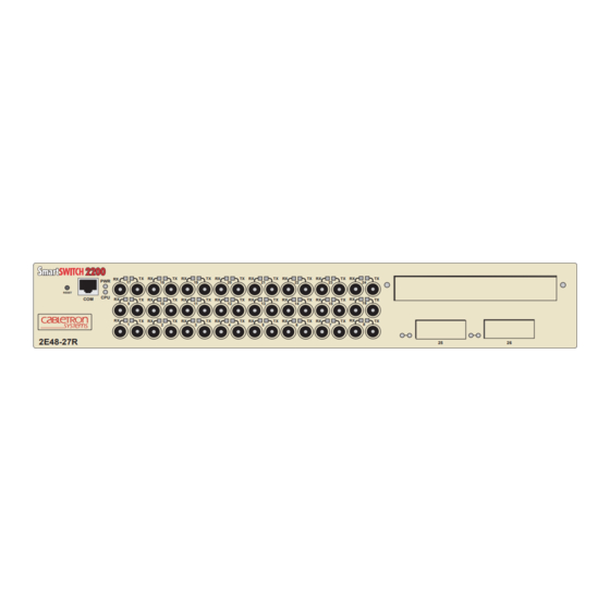
Page 14: 2E4X-27R Overview
The 2E48-27R and 2E49-27R, shown in except that ports 1 through 24 of the 2E48-27R support multimode fiber optic cabling while ports 1 through 24 of the 2E49-27R support single mode fiber optic cabling. - Page 15 System LEDs COM Port 2E49-27R Figure 1-1 The 2E48-27R and 2E49-27R The 2E4X-27R is a tabletop unit that can be installed in a standard 19-inch rack using the supplied rack mounting hardware. The 2E4X-27R has two power supplies. The power supplies load share 50% (+/-5%) of the power required by the device.
-
Page 16: Connectivity
Chapter 1: Introduction 1.3.1 Connectivity The 2E48-27R connects to Ethernet networks or workstations through 24 ST fiber optic ports on the front panel. These ports support multimode fiber optic cables at lengths up to 2 kilometers. The ports are IEEE 802.3 10BASE-F compliant. -
Page 17: Runtime Ip Address Discovery
For more information about SmartTrunk, refer to the Cabletron Systems SmartTrunk User’s Guide. 1.3.4 Runtime IP Address Discovery This feature enables the 2E4X-27R to automatically accept an IP address from a Boot Strap Protocol (BootP) server on the network into NVRAM without requiring a user to enter an IP address through Local Management. -
Page 18: Switching Options
MIBs including RFC 1213 (MIB II), RFC 1757 (RMON), RFC 1493 (Bridge MIB) and RFC 1354 (FIB MIB). A full suite of Cabletron Systems Enterprise MIBs provide a wide array of statistical information to enhance troubleshooting. -
Page 19: Optional Features
Options for the 2E4X-27R are Fast Ethernet Interface Modules and High Speed Interface Modules, which add remote uplink capability. Cabletron Systems provides Fast Ethernet Interface Modules to support uplinks to 100 Mbps Ethernet backbones or high speed connections to local servers. -
Page 20: Document Conventions
CAUTION Electrical Hazard Warning symbol. Warns against an action that could result in personal injury or death due to an electrical hazard. Warning symbol. Warns against an action that could result in personal injury or death. WARNING 2E48-27R/2E49-27R User’s Guide... -
Page 21: Getting Help
Cabletron Systems Technical Writing Department via the following email address: TechWriting@cabletron.com Make sure to include the document Part Number in the email message. Before calling the Cabletron Systems Global Call Center, have the following information ready: • Your Cabletron Systems service contract number •... -
Page 22: Related Manuals
These manuals can be obtained from the World Wide Web in Adobe Acrobat Portable Document Format (PDF) at the following site: http://www.cabletron.com/ All documentation for the Cabletron Systems SecureFast VLAN NOTE Manager software is contained on the VLAN Manager CD-ROM. -
Page 23: Chapter 2 Network Requirements
Cabletron Systems SmartTrunk User’s Guide for additional information. 10BASE-F NETWORK When connecting a 10BASE-F segment to any of the 2E48-27R ports (Interfaces 1 through 24), ensure that the network meets the Ethernet network requirements of the IEEE 802.3 standard for 10BASE-F. Refer to the Cabletron Systems Cabling Guide for details. -
Page 24: Foirl Fiber Optic Network
100BASE-FX FIBER OPTIC NETWORK Ports 25 and 26 of the 2E4X-27R support the Cabletron Systems FE-100FX and FE-100F3 fiber optic interface modules. The device at the other end of the fiber optic segment must meet the 100BASE-FX Fast Ethernet network requirements to operate at 100 Mbps. -
Page 25: Chapter 3 Installation
• Connecting to the Network • Completing the Installation UNPACKING THE 2E4X-27R Unpack the 2E4X-27R as follows: Open the box and remove the packing material protecting the 2E4X-27R. 2E48-27R/2E49-27R User’s Guide CHAPTER 3 INSTALLATION (Section 3.1) (Section 3.2) (Section 3.4) (Section 3.5) -
Page 26: Installing Options
Remove the black and amber tape seal on the non-conductive bag to remove the 2E4X-27R. Perform a visual inspection of the device for any signs of physical damage, and contact the Cabletron Systems Global Call Center if there are any signs of damage. Refer to INSTALLING OPTIONS... -
Page 27: Installing The Device
To ensure proper ventilation and prevent overheating, leave a minimum clearance space of 5.1 cm (2.0 in) at the left, right, CAUTION and rear of the 2E4X-27R. 2E48-27R/2E49-27R User’s Guide Section 3.3.3 for power connection instructions. Installing the Device Section 3.3.2... -
Page 28: Rackmount Installation
Figure 3-1 Tabletop or Shelf Installation 3.3.2 Rackmount Installation To install the 2E4X-27R in a 19-inch rack, Cabletron Systems includes an accessory kit containing the rackmount brackets, mounting screws, and a strain-relief bracket for cable management. Guidelines for the Rackmount Installation... - Page 29 Then attach the strain-relief bracket to the bottom of the 2E4X-27R using the four 8-32 x 3/8-inch pan-head screws. Strain-Relief Bracket Figure 3-2 Attaching the Strain-Relief Bracket 2E48-27R/2E49-27R User’s Guide Screws (4) Installing the Device Figure 3-2) on a clean...
- Page 30 19-inch rack and fasten it securely with mounting screws as shown in RESET 2E48-27R Figure 3-4 Installing the 2E4X-27R in a Rack Figure 3-3. Rackmount Brackets (2) Screws (4) Figure 19-Inch Rack Screws (4) 2E48-27R/2E49-27R User’s Guide 23141-04 3-4. 23141-03...
-
Page 31: Connecting Power To The 2E4X-27R
Check the power cord connections and the power source. If there are no problems with the power cord connections or power source and the CPU LED is still not green, contact the Cabletron Systems Global Call Center. Refer to Section 1.5 for details. -
Page 32: Connecting To The Network
SmartTrunk User’s Guide for the configuration information. Ports 1 through 24 on the 2E48-27R has ST connectors for multimode fiber optic cable connections. Ports 1 through 24 on the 2E49-27R has ST connectors for single mode fiber optic cable connections. On all of these devices, ports 25 and 26 support FE-100TX, FE-100FX, or FE-100F3 Fast Ethernet Interface Modules. -
Page 33: Connecting Fiber Optic Cables To Ports 1
2E4X-27R connects to the transmit port of the fiber optic Ethernet device. Cabletron Systems recommends labeling fiber optic cables to indicate receive and transmit ends. Many cables are prelabeled, providing matching labels or tapes at both ends of each strand of cable. -
Page 34: Connecting A Utp Segment To The Fe-100Tx
Check the cable for continuity. Check that the fiber optic connection meets the dB loss and cable specifications outlined in multimode or single mode cabling, respectively. If a link is not established, contact Cabletron Systems Global Call Center. Refer to Section 1.5 for details. - Page 35 7. NC 4. NC 8. NC Figure 3-7 FE-100TX Crossover Switch A schematic of a crossover cable is shown in not cross over, use the switch on the FE-100TX to internally cross over the RJ45 port. Figure 3-7 crossover switch. NOTE: RX+/RX–...
-
Page 36: Connecting A Fiber Optic Segment To The Fe-100Fx And Fe-100F3
Make sure that the twisted pair connection meets the db loss and cable specifications outlined in Confirm that the crossover switch is in the correct position. If a link is not established, contact the Cabletron Systems Global Call Center. Refer to Section 1.5 3.4.3... - Page 37 2E4X-27R. See At the other end of the fiber optic cable, attach the SC connector to the other device. Figure 3-9 FE-100FX or FE-100F3 Port Connection 2E48-27R/2E49-27R User’s Guide Connecting to the Network Figure 3-9. TX LED...
-
Page 38: Completing The Installation
Verify that the fiber connection meets the dB loss specifications outlined in Section If a link has not been established, contact the Cabletron Systems Global Call Center. Refer to Section 1.5 COMPLETING THE INSTALLATION... -
Page 39: Chapter 4 Troubleshooting
Troubleshooting Checklist • Using the RESET Button USING LANVIEW The 2E4X-27R uses the Cabletron Systems built-in visual diagnostic and status monitoring system called LANVIEW. The LANVIEW LEDs (Figure 4-1) allow quick observation of the network status to aid in diagnosing network problems. Refer to LEDs. - Page 40 Blinking. Crippled. Solid. Testing. Solid. Functional. Booting. Blinks amber and green while booting. 2E48-27R/2E49-27R User’s Guide Recommended Action 1. Ensure that the power cords are plugged in correctly and that there is power at the power source. 2. Contact the Cabletron Systems Global Call Center (GCC).
- Page 41 Table 4-1 LANVIEW LEDs (Continued) Color (Receive) Green Amber (Transmit) Green Amber 2E48-27R/2E49-27R User’s Guide State No link. No activity. Port enabled or disabled. Solid. Port enabled, link, no activity. Blinking. Port disabled, link. Flashing. Port enabled, link, activity. Diagnostic failure.
-
Page 42: Fe-100Tx Led
Table 4-2 10/100 LED Indications When RX LED Is On Color 10/100 Green provide a functional description of the 10/100 FE-100TX 2 2 5 Indication FE-100TX is operating at 10 Mbps. FE-100TX is operating at 100 Mbps. 2E48-27R/2E49-27R User’s Guide Figure 4-2. 19602-41... - Page 43 LED is off. Table 4-3 10/100 LED Indications When RX LED Is Off Color 10/100 Green 2E48-27R/2E49-27R User’s Guide Indication No link or no cable attached. FE-100TX forced to 10 Mbps operation, or is manually set to “auto-negotiate” mode. No link or no cable attached. FE-100TX is forced to 100 Mbps operation.
-
Page 44: Troubleshooting Checklist
Enable port. Check link to device. 1. Review network design and delete unnecessary loops. 2. Call the Cabletron Systems GCC if the problem continues. 1. Reenter the lost parameters as necessary. 2. Call the Cabletron Systems GCC if the problem continues. -
Page 45: Using The Reset Button
To reset the 2E4X-27R processor, press and release the RESET button. The 2E4X-27R goes through a reset process for approximately 45 seconds. Additional downtime may result as the device reenters the network. 2E48-27R/2E49-27R User’s Guide Figure 4-3 resets the 2E4X-27R processor RESET... - Page 46 Chapter 4: Troubleshooting 2E48-27R/2E49-27R User’s Guide...
-
Page 47: Chapter 5 Local Management
There are three ways to access Local Management: • Locally using a VT type terminal connected to the COM port. • Remotely using a VT type terminal connected through a modem. • In-band through a Telnet connection. 2E48-27R/2E49-27R User’s Guide CHAPTER 5... -
Page 48: Local Management Keyboard Conventions
Management increment field. For example, “Press [–]” means to press the minus sign key. The DEL (Delete) key removes characters from a Local Management field. For example, “Press DEL” means to press the Delete key. 2E48-27R/2E49-27R User’s Guide Table 5-1 explains... -
Page 49: Management Terminal Setup
A Digital Equipment Corporation VT100 type terminal • A VT type terminal running emulation programs for the Digital Equipment Corporation VT100 series • A remote VT100 type terminal via a modem connection • In-band via a Telnet connection 2E48-27R/2E49-27R User’s Guide Management Terminal Setup... -
Page 50: Console Cable Connection
Plug the RJ45 connector at the other end of the cable into the RJ45-to-DB9 adapter (supplied in the kit). Connect the RJ45-to-DB9 adapter to the communications port on the PC. RESET 2E48-27R RJ45 COM Port Figure 5-1 Management Terminal Connection UTP Cable with RJ45 Connectors RJ45-to-DB9 PC Adapter 2E48-27R/2E49-27R User’s Guide 23141-50... -
Page 51: Management Terminal Setup Parameters
Auto Answerback -> Keyboard Setup Menu Keys -> Auto Repeat -> Keyclick -> Margin Bell -> Warning Bell -> 2E48-27R/2E49-27R User’s Guide Management Terminal Setup Table 5-2 VT Terminal Setup 80 Columns Interpret Controls No Auto Wrap Jump Scroll Cursor... -
Page 52: Telnet Connections
For information about setting the IP address, refer to Section 5.7. For information about assigning community names, refer to Section 5.8. Refer to the instructions included with the Telnet application for information about establishing a Telnet session. 2E48-27R/2E49-27R User’s Guide... -
Page 53: Monitoring An Uninterruptible Power Supply
Connect the RJ45 connector at one end of the cable to the COM port on the 2E4X-27R. Plug the RJ45 connector at the other end of the cable into the RJ45-to-DB9 male (UPS) adapter (Cabletron Systems part number, 9372066). Connect the RJ45-to-DB9 male (UPS) adapter to the female DB9 port on the rear of the UPS device (refer to the particular UPS device’s user... -
Page 54: Accessing Local Management
Figure Section 2E48-27R LOCAL MANAGEMENT CABLETRON Systems, Incorporated P.O.Box 5005 Rochester, NH 03866-5005 USA (603) 332-9400 (c) Copyright CABLETRON Systems, Inc, 1997 Device Serial Number: Device Hardware Revision: Device Firmware Revision: Device BOOTPROM Revision: Enter Password: 2E48-27R/2E49-27R User’s Guide 5-3. Whenever a 5.8. -
Page 55: Navigating Local Management Screens
802.1D SWITCHING (IEEE 802.1D switching) • 802.1Q SWITCHING (IEEE 802.1Q port based VLANs) • SECURE FAST VLAN (Cabletron Systems SecureFast switching) Refer to the Release Notes shipped with the product to verify NOTE which screens are supported in each of the three available switching modes. - Page 56 Ethernet Full Duplex Configuration SmartTrunk Configuration System Device Specific Resources Configuration Menu High Speed Interface Configuration Switch Statistics Flash Download Interface Statistics Broadcast RMON Statistics Suppression 802.1Q VLAN Configuration 2E48-27R/2E49-27R User’s Guide Fast Ethernet Interfaces HSIM 23142-43 Fast Ethernet Interfaces HSIM 19601-82...
-
Page 57: Selecting Local Management Menu Screen Items
Use the arrow keys to highlight the EXIT command at the bottom of the Local Management screen. Press ENTER. The Local Management Password screen displays and the session ends. 2E48-27R/2E49-27R User’s Guide Accessing Local Management General Configuration SNMP Community Names... - Page 58 Device Menu screen displays. To end the LM session, use the arrow keys to highlight the RETURN command at the bottom of the Device Menu screen. Press ENTER. The Local Management Password screen displays and the session ends. 5-12 2E48-27R/2E49-27R User’s Guide...
-
Page 59: Device Menu Screen
The Device Menu screen is the access point for all Local Management screens. Figure 5-7 shows the Device Menu screen. Device Type: 2E48-27R Figure 5-7 Device Menu Screen If the terminal is idle for several minutes, the Local NOTE Management Password screen redisplays and the session ends. -
Page 60: Device Statistics
Section DEVICE STATISTICS Device Statistics accesses the Device Menu screen, which provides access to screens that allow the user to obtain switch, interface, and RMON statistics information about the 2E4X-27R. For details, refer to Section 5.19. NETWORK TOOLS... -
Page 61: General Configuration
DEVICE CONFIGURATION menu item and press ENTER. The Device Configuration Menu screen displays. Device Type: 2E48-27R Figure 5-8 Device Configuration Menu Screen The following briefly explains each screen that is accessible from the Device Configuration Menu screen:... - Page 62 For details, refer to Section 5.9. SWITCH CONFIGURATION The Switch Configuration screen provides the basic setup options for customizing the operation of a switch device in the network. For details, refer to Section 5.10. ETHERNET FULL DUPLEX CONFIGURATION The Ethernet Full Duplex Configuration screen allows each 10 Mbps port (1 to 24) to be set for either Standard Ethernet or Full Duplex operation.
-
Page 63: General Configuration Screen
To access the General Configuration screen from the Device Configuration Menu screen, use the arrow keys to highlight the GENERAL CONFIGURATION menu item and press ENTER. The General Configuration screen displays. Event Message Line Device Type: 2E48-27R MAC Address: IP Address: Subnet Mask: Default Gateway: TFTP Gateway IP Addr: Operational Mode: [802.1D SWITCHING]... - Page 64 Screen Refresh Time (Modifiable) Contains the rate at which the screens are updated. This setting determines how frequently (in seconds) information is updated on the screen. To enter a new update time, refer to Section 5.7.7. 5-18 2E48-27R/2E49-27R User’s Guide...
- Page 65 VLANs. When the operational mode is set to SECURE FAST VLAN, the 2E4X-27R acts as a SecureFast switch. With the Cabletron Systems VLAN Manager software, the 2E4X-27R is able to increase its switching functionality by creating and maintaining Virtual LANs (VLANs).
-
Page 66: Setting The Ip Address
IP address field. If the entry is not valid, the screen displays the message “INVALID IP ADDRESS OR FORMAT ENTERED”. Local Management does not alter the current value and refreshes the IP address field with the previous value. 5-20 Section 5.7.12. 2E48-27R/2E49-27R User’s Guide... -
Page 67: Setting The Subnet Mask
To change the subnet mask from its default, perform the following steps: Use the arrow keys to highlight the Subnet Mask field. Enter the subnet mask into this field using Dotted Decimal Notation (DDN) format. For example: 255.255.0.0 2E48-27R/2E49-27R User’s Guide General Configuration Screen Figure 5-11 WARNING! displays. - Page 68 ARE YOU SURE YOU WANT TO CONTINUE? Figure 5-11 Configuration Warning Screen Use the arrow keys to highlight the YES command, then press ENTER. The changes are saved and the device reboots. 5-22 Figure 5-11 WARNING! 2E48-27R/2E49-27R User’s Guide displays. 19601-84...
-
Page 69: Setting The Default Gateway
Management does not alter the current value, but it does refresh the TFTP Gateway IP Address field with the previous value. Use the arrow keys to highlight the SAVE command, then press ENTER. The warning screen shown in 2E48-27R/2E49-27R User’s Guide General Configuration Screen Figure 5-12 displays. -
Page 70: Setting The Device Date
For example, to set the date to 03/17/1997, type “03171997” in the Device Date field. Press ENTER to set the system calendar to the date in the input field. 5-24 WARNING! 2E48-27R/2E49-27R User’s Guide 19601-84... -
Page 71: Setting The Device Time
Use the arrow keys to highlight the Screen Refresh Time field. Enter a number from 3 to 99. Press ENTER to set the refresh time to the time entered in the input field. 2E48-27R/2E49-27R User’s Guide General Configuration Screen ., type “184500” in the Device Time field. 5-25... -
Page 72: Setting The Screen Lockout Time
Setting the Operational Mode If the device is to be configured to operate as a SecureFast NOTE switch, the device must be assigned a unique IP address that has been saved (i.e., the device has rebooted and the new IP address is active). - Page 73 Port Based VLAN User’s Guide to configure the devices for this type of operation. If the 2E4X-27R is set to SECURE FAST VLAN, refer to your SecureFast documentation set to configure the devices for this type of operation. 2E48-27R/2E49-27R User’s Guide General Configuration Screen WARNING! 19601-84 5-27...
-
Page 74: Configuring The Com Port
If the COM port is reconfigured without a valid IP address set on the device, the message shown in CAUTION Do not continue unless the outcome of the action is fully understood. 5-28 Appendix Figure 5-14 2E48-27R/2E49-27R User’s Guide C) to displays. - Page 75 SAVE at the bottom of the screen, then press ENTER. Exiting without saving causes the message “NOT SAVED -- NOTE PRESS SAVE TO KEEP CHANGES” to appear. Exiting without saving causes all edits to be lost. 2E48-27R/2E49-27R User’s Guide General Configuration Screen WARNING 174252 5-29...
-
Page 76: Changing The Com Port Application
IP address and the changes are saved, refer to Appendix C reestablish COM port communications. 5-30 Application Local Management Session APC Power Supply SNMP Proxy for instructions on clearing NVRAM in order to 2E48-27R/2E49-27R User’s Guide Section 5.7.10, one of the Table 5-3 lists the... -
Page 77: Clearing Nvram
Use the arrow keys to select YES and press ENTER. The message “CLEARING NVRAM. REBOOT IN PROGRESS...” displays. The 2E4X-27R clears NVRAM and reboots. All user-entered parameters default to factory default settings. 2E48-27R/2E49-27R User’s Guide General Configuration Screen Figure 5-15 WARNING displays. -
Page 78: Enabling/Disabling Ip Fragmentation
Use the arrow keys to highlight the IP Fragmentation field. Press the SPACE bar to choose either ENABLED or DISABLED. Use the arrow keys to highlight the SAVE command. Press ENTER. The message “SAVED OK” displays at the top of the screen. 5-32 2E48-27R/2E49-27R User’s Guide... -
Page 79: Snmp Community Names Screen
Configuration Menu screen, use the arrow keys to highlight the SNMP COMMUNITY NAMES menu item and press ENTER. The SNMP Community Names screen displays. Event Message Line Device Type: 2E48-27R SAVE Figure 5-16 SNMP Community Names Screen 2E48-27R/2E49-27R User’s Guide... - Page 80 fields for Super-User access only. This community name gives the user read-write access to the 2E4X-27R MIB objects and allows the user to change all modifiable parameters including community names, IP addresses, traps, and SNMP objects. 2E48-27R/2E49-27R User’s Guide...
-
Page 81: Establishing Community Names
The community names are saved to memory and their access modes implemented. Exiting without saving causes a “NOT SAVED?” message to NOTE display above the SAVE command. Edits are lost if they are not saved before exiting. 2E48-27R/2E49-27R User’s Guide SNMP Community Names Screen 5-35... -
Page 82: Snmp Traps Screen
To access the SNMP Traps screen from the Device Configuration Menu screen, use the arrow keys to highlight the SNMP TRAPS menu item and press ENTER. The SNMP Traps screen displays. Event Message Line Device Type: 2E48-27R Trap Destination 0.0.0.0 0.0.0.0 0.0.0.0... -
Page 83: Configuring The Trap Table
Exiting without saving causes a “NOT SAVED?” message to NOTE appear above the SAVE command. Edits are lost if they are not saved before exiting. The designated workstations now receive traps from the 2E4X-27R. 2E48-27R/2E49-27R User’s Guide SNMP Traps Screen 5-37... -
Page 84: Switch Configuration Screen
This screen may only be used when the device is configured to operate as an 802.1D or 802.1Q switch. To access the Switch Configuration screen from the Device Configuration Menu screen, use the arrow keys to highlight the SWITCH CONFIGURATION menu item and press ENTER. The Switch Configuration screen displays showing ports 1 through 8. - Page 85 Type of STA (Toggle) Allows the user to set the method that switches use to decide which switch is the controlling (Root) switch when two or more switches exist in parallel (Spanning Tree Algorithm). Valid selection is IEEE, DEC, and None.
-
Page 86: Setting The Sta
The Spanning Tree Algorithm (STA) setting allows the user to set the method that the switches use to decide which is the controller (Root) switch when two or more switches are in parallel. The available selections are IEEE, DEC, and NONE. -
Page 87: Setting The Age Time Field
Use the SPACE bar to toggle to either ENABLED or DISABLED. Use the arrow keys to highlight the SAVE command at the bottom of the screen. Press ENTER. The message “SAVED OK” displays. 2E48-27R/2E49-27R User’s Guide Switch Configuration Screen 5-41... -
Page 88: Ethernet Full Duplex Configuration Screen
Configuration Menu screen, use the arrow keys to highlight the ETHERNET FULL DUPLEX CONFIGURATION menu item and press ENTER. The Ethernet Full Duplex Configuration screen displays. Event Message Line Device Type: 2E48-27R OPERATION MODE PORT # [STANDARD ENET] [STANDARD ENET]... - Page 89 Ethernet ports for Standard operation, refer to • FULL DUPLEX – The port transmits and receives data simultaneously at 10 Mbps, thus enabling the port to effectively switch at 20 Mbps. To set Ethernet ports for Full Duplex operation, refer to Section 5.11.1.
-
Page 90: Setting The Operation Mode
Use the arrow keys to highlight the SET ALL PORTS field. Press the SPACE bar until you see FULL or STANDARD. Use the arrow keys to highlight the SAVE command. Press ENTER. The message “SAVED OK” displays. 5-44 2E48-27R/2E49-27R User’s Guide... -
Page 91: Device Specific Configuration Menu Screen
Device Configuration Menu screen, use the arrow keys to highlight the DEVICE SPECIFIC CONFIGURATION menu item and press ENTER. The Device Specific Configuration Menu screen displays. Device Type: 2E48-27R Figure 5-20 Device Specific Configuration Menu Screen 2E48-27R/2E49-27R User’s Guide Device Specific Configuration Menu Screen Section 5.7.9... - Page 92 Operation Mode. When selected, this menu item opens the VLAN Main Menu screen. For details about the VLAN Local Management screens and how to use them to configure VLANs in the 2E4X-27R, refer to the Cabletron Systems Port Based VLAN User’s Guide. 5-46 5.16.
-
Page 93: System Resources Screen
FLASH memory, DRAM, and NVRAM that is installed and how much of that memory is available. This screen also allows the user to monitor the current processor (switch) utilization and the peak switch utilization. To access the System Resources screen from the Device Specific Configuration Menu screen, use the arrow keys to highlight the SYSTEM... -
Page 94: Setting The Reset Peak Switch Utilization
Peak Switch Utilization field to the current system traffic. 5.13.1 Setting the Reset Peak Switch Utilization To set the Reset Peak Switch Utilization field to YES or NO, proceed as follows: Use the arrow keys to highlight the Reset Peak Switch Utilization field. -
Page 95: High Speed Interface Configuration Menu Screen
Device Specific Configuration Menu screen, use the arrow keys to highlight the HIGH SPEED INTERFACE CONFIGURATION menu item and press ENTER. The High Speed Interface Configuration Menu screen displays. Device Type: 2E48-27R Figure 5-22 High Speed Interface Configuration Menu Screen 2E48-27R/2E49-27R User’s Guide 2E48-27R LOCAL MANAGEMENT... -
Page 96: High Speed Interface Configuration Screen
To access the High Speed Interface Configuration screen from the High Speed Interface Configuration Menu screen, use the arrow keys to highlight the FAST ETHERNET INTERFACES menu item and press ENTER. The High Speed Interface Configuration screen displays. 5-50 Section 5.15. Figure 5-23 2E48-27R/2E49-27R User’s Guide... - Page 97 Event Message Line Device Type: 2E48-27R Port Type Link Status Current Oper. Mode Desired Oper. Mode Advertised Ability SAVE Figure 5-23 High Speed Interface Configuration Screen The following briefly defines each field of the High Speed Interface Configuration screen. Port Type (Read-only) Displays the type of interface (FE-100FX, FE-100TX, FE-100F3, or Unknown) installed in ports 25 and 26.
- Page 98 In Auto-Negotiation, the FE-100TX negotiates to the highest common denominator of the two interfaces. The order of priority of negotiation is 100Base-TXFD, 100Base-TX, 10Base-TFD, and 10Base-T. 5-52 describes how to configure a port with an describes how to manually configure an 2E48-27R/2E49-27R User’s Guide...
-
Page 99: Configuring An Fe-100Fx Or Fe-100F3
Use the arrow keys to highlight the SAVE command. Press ENTER. The message “SAVED OK” displays and Local Management saves the changes to memory. 2E48-27R/2E49-27R User’s Guide High Speed Interface Configuration Screen describes how to enable or disable advertised Section 5.15.1.1... -
Page 100: Configuring An Fe-100Tx
This field steps to 10Base-T, 10Base-TFD (full duplex), 100Base-TX, and 100Base-TXFD (full duplex). To set the advertised ability, proceed as follows: Use the arrow keys to highlight the Advertised Ability field. Use the SPACE bar to select the desired mode. 5-54 Section 5.15.2.1 2E48-27R/2E49-27R User’s Guide... -
Page 101: Flash Download Screen
file downloaded from a TFTP server. The user may also force the download of an image by changing NOTE the position of Switch 6 located inside the device. Refer to Section C.2.1, Before downloading an image to the device, copy the image to the network TFTP server. -
Page 102: Screen Displays
Configuration Menu screen, use the arrow keys to highlight the FLASH DOWNLOAD menu item and press ENTER. The Flash Download screen displays. TFTP DOWNLOAD. WILL COMMIT TO FLASH. REBOOT IN PROGRESS... Device Type: 2E48-27R EXECUTE Figure 5-24 Flash Download Screen Download Server IP and Download File Name display only NOTE when TFTP or RUNTIME are selected in Download Method. - Page 103 field. Download File Name (Selectable) The complete TFTP Server path and file name of the new image is entered in this field. 2E48-27R/2E49-27R User’s Guide Section 5.7.4, Setting the TFTP Gateway Figure 5-24), the following two additional fields FLASH Download Screen Section 5.16.3...
-
Page 104: Image File Download Using Bootp
Enter the IP address of the TFTP server using the DDN format. For example: 134.141.79.121 Use the arrow keys to highlight the Download File Name field. Enter the complete pathway and file name of the image stored on the download server. For example: /tftpboot/2E48.hex 5-58 2E48-27R/2E49-27R User’s Guide... -
Page 105: Image File Download Using Runtime
ENTER. The message “TFTP DOWNLOAD. WILL COMMIT TO FLASH. REBOOT IN PROGRESS...” displays in the event message line at the top of the screen and the new image is downloaded into FLASH memory. 2E48-27R/2E49-27R User’s Guide FLASH Download Screen 5-59... -
Page 106: Port Redirect Function Screen
To access the Port Redirect Function screen from the Device Specific Configuration Menu screen, use the arrow keys to highlight the PORT REDIRECT FUNCTION menu item and press ENTER. The Port Redirect Function screen displays. 5-60 Section 5.7.9 Figure 5-25, allows the user to set 2E48-27R/2E49-27R User’s Guide describes how... - Page 107 Event Message Line Device Type: 2E48-27R Source Port: ============ Source Port [1] SAVE Figure 5-25 Port Redirect Function Screen The following definitions briefly explain each field of the Port Redirect Function screen: Source Port (Read-only) Shows which ports are currently set as source ports.
-
Page 108: Displaying The Source And Destination Entries
To display the next screen, use the arrow keys to highlight NEXT. Press ENTER and the next screen of entries displays. To display the previous screen, use the arrow keys to highlight PREVIOUS. Press ENTER to view the entries on the previous screen. 5-62 2E48-27R/2E49-27R User’s Guide... -
Page 109: Changing Source And Destination Ports
Use the arrow keys to highlight SAVE at the bottom of the screen. Press ENTER. The message “SAVED OK” displays. This saves the new settings and updates the Source Port and Destination Port read-only fields. 2E48-27R/2E49-27R User’s Guide Port Redirect Function Screen 5-63... -
Page 110: Broadcast Suppression Screen
To access the Broadcast Suppression screen from the Device Specific Configuration Menu screen, use the arrow keys to highlight the BROADCAST SUPPRESSION menu item and press ENTER. The Broadcast Suppression screen displays. Event Message Line Device Type: 2E48-27R PORT # Total RX 12345678910 12345678910... -
Page 111: Setting The Threshold
Use the arrow keys to highlight the Threshold field for the selected port. Type in the numbers for the desired limit. Only enter values in increments of ten (for example; 10, 20, 30, etc.). 2E48-27R/2E49-27R User’s Guide Broadcast Suppression Screen Section 5.18.1. -
Page 112: Setting The Reset Peak
DEVICE STATISTICS MENU SCREEN The Device Statistics Menu screen, screens that allow the user to obtain switch statistics about frame traffic through each port and view operating statistics about each port. The SWITCH STATISTICS menu item on the Device Statistics... -
Page 113: Switch Statistics
Figure 5-27 Device Statistics Menu Screen The Device Statistics Menu screen displays the following menu items: SWITCH STATISTICS The Switch Statistics screen lists the number of frames received, transmitted, filtered, and forwarded by each interface. For details, refer to Section 5.20. -
Page 114: Switch Statistics Screen
SECURE FAST VLAN. Section 5.7.9 To access the Switch Statistics screen from the Device Statistics Menu screen, use the arrow keys to highlight the SWITCH STATISTICS menu item and press ENTER. The Switch Statistics screen displays. -
Page 115: Using The Clear Counters Command
Displays the number of frames forwarded by the interface. [1-12], [13-24], or [25-27] (Navigation Key) When the Switch Statistics screen displays, the statistics are displayed for the first 12 ports. These fields allow the user to step to a second or third screen for the same type of information for ports 13 through 24 or 25 through 27. -
Page 116: Interface Statistics Screen
The Interface Statistics screen, statistics for the 2E4X-27R interfaces (ports 1 through 26) with the exception of an installed HSIM. Cabletron Systems HSIMs gather their own statistics, and may NOTE be viewed via the Local Management screens of the applicable HSIM. - Page 117 This field may increment because it was in an initialization phase and not ready to forward frames, the switch needed to free up buffer space, or the switch was being overutilized.
- Page 118 The OutDiscards field displays the total number of outbound frames that were discarded, even though the frames contained no errors. This field may increment, because the switch needed to free up buffer space, or the switch was being overutilized. OutErrors (Read-Only) This field displays the total number of outbound frames discarded...
-
Page 119: Displaying Interface Statistics
Press the SPACE bar to increment (or press the DEL [delete] key to decrement) the interface number. Press ENTER (neither the Interface # fields nor the statistics will change until ENTER is pressed). 2E48-27R/2E49-27R User’s Guide Interface Statistics Screen Section 5.21.2. -
Page 120: Using The Clear Counters Command
To access the RMON Statistics screen, use the arrow keys to highlight the RMON STATISTICS field on the Device Statistics Menu screen and press ENTER. The RMON Statistics screen displays. Event Message Line Device Type: 2E48-27R RMON Index: Data Source: IfIndex.1... - Page 121 Drop Events (Read-only) This field displays the total number of times that the RMON agent was forced to discard frames due to the lack of available switch resources. The Drop Events field does not display the number of frames NOTE dropped, it only displays the number of times that the RMON agent was forced to discard frames.
- Page 122 This field displays the total number of frames that were greater than 1518 bytes and had either a bad FCS or a bad CRC. Total Packets (Read-only) This field displays the total number of frames (including bad frames, broadcast frames, and multicast frames) received on this interface. 5-76 2E48-27R/2E49-27R User’s Guide...
- Page 123 Section 5.22.1. CLEAR COUNTERS (Command) This command is used to reset all statistic counters to zero. For details on how to use this command, refer to Section 5.22.2. 2E48-27R/2E49-27R User’s Guide 5-77...
-
Page 124: Displaying Rmon Statistics
To reset all the statistics counters of the selected interface to zero, perform the following steps: Use the arrow keys to highlight the CLEAR COUNTERS field. Press ENTER, the counters for the selected index are reset to zero. 5-78 2E48-27R/2E49-27R User’s Guide... -
Page 125: Network Tools
A command used incorrectly (wrong syntax) will prompt a display of the correct usage. Use lower case characters when entering commands in Network Tools. 2E48-27R/2E49-27R User’s Guide shows the Network Tools Help screen. defroute reset... - Page 126 Shows the required command format. It indicates where arguments, if any, must be specified. Briefly describes the command and its uses. Lists any additional fields in the appropriate format which may be added to the command. Shows an example of the command. 2E48-27R/2E49-27R User’s Guide...
-
Page 127: Built-In Commands
Syntax: Description: You must specify the arp command with one of the following options: Options: 2E48-27R/2E49-27R User’s Guide arp [options] The arp command provides access to the ARP (Address Resolution Protocol) cache, enabling you to view cache data, delete entries, or add a static route. - Page 128 Specifying a single interface number will affect the bridging status of that interface, while specifying ALL will affect every interface. Not Applicable 2E48-27R/2E49-27R User’s Guide Media Type 3(dynamic) 3(dynamic) 3(dynamic)
- Page 129 # Default route is not currently set. -> netstat: Syntax: Description: Options: 2E48-27R/2E49-27R User’s Guide defroute defroute [interface number] [IP address] defroute delete [interface number] [IP address] The defroute command allows the user, in the syntax order shown above, to view, set, or delete the default IP route to a managed device through the specified interface.
- Page 130 NVRAM. The user will be queried to confirm the reset command to ensure against unwanted resets. 2E48-27R/2E49-27R User’s Guide MAC Addr 0x00 0x00 0x1d 0x07 0x50 0x0e 0x00 0x00 0x1d 0x07 0x50 0x0f...
- Page 131 -> show IP ARP # Interface MediaType 3 (dynamic) 3 (dynamic) # Number of valid entries: 2 2E48-27R/2E49-27R User’s Guide Not Applicable show [PROTOCOL] <TABLE> The show command displays information concerning various components of the device. Protocols currently supported are IP, IPX, DECnet, and AppleTalk.
- Page 132 Not Applicable soft_reset This command restarts the software image, which restores the user configuration settings from NVRAM. The user will be queried to confirm the reset command to ensure against unwanted resets. Not Applicable 2E48-27R/2E49-27R User’s Guide 05141-77 22512-76...
- Page 133 Syntax: Description: Options: 2E48-27R/2E49-27R User’s Guide telnet [IP address] <Port #> The telnet command allows the user to communicate with another host (that supports Telnet connections) using the Telnet protocol. The user must specify the remote host using its IP address.
- Page 134 Spanning Tree Algorithm on all ATM interfaces. The user must specify the STATE option as enable, disable, or status. enable, disable, status -> atm_stp_state status Atm Stp is Enabled -> atm_stp_state disable -> atm_stp_state enable 2E48-27R/2E49-27R User’s Guide 2314-78 2314-79...
-
Page 135: Special Commands
Syntax: Description: Options: Example: -> done 2E48-27R/2E49-27R User’s Guide done, quit, or exit The done, quit, or exit command enables the user to exit from Network Tools and return to the Main Menu screen. Not Applicable Network Tools... - Page 136 Chapter 5: Local Management 5-90 2E48-27R/2E49-27R User’s Guide...
-
Page 137: A.3 Electrical Specifications
This appendix provides operating specifications for the Cabletron Systems 2E4X-27R. Cabletron Systems reserves the right to change these specifications at any time without notice. DEVICE SPECIFICATIONS Processor: Dynamic Random Access Memory (DRAM): FLASH Memory: PHYSICAL PROPERTIES Dimensions: Weight (Unit) :... -
Page 138: A.4 Environmental Requirements
Operating Temperature: Storage Temperature: Operating Relative Humidity: INPUT/OUTPUT PORTS 2E48-27R, Ports 1 through 24: Ethernet multimode fiber optic (802.3 2E49-27R, Ports 1 through 24: Ethernet single mode fiber optic (FOIRL Slots for optional ports 25 and 26: Slot for optional port 27: 5°C to 40°C (41°F to 104°F) -
Page 139: A.7 Regulatory Compliance
Data Terminal Ready (DTR) Request to Send (RTS) Clear to Send (CTS) REGULATORY COMPLIANCE This equipment meets the following safety and electromagnetic compatibility (EMC) requirements: Safety Electromagnetic Compatibility (EMC) 2E48-27R/2E49-27R User’s Guide COM Port/Pin Assignments Input/Output Output Output Input Input Output Input UL 1950, CSA C22.2 No. - Page 140 Appendix A: Specifications 2E48-27R/2E49-27R User’s Guide...
-
Page 141: B.1 Fe-100Tx
111 ohms. The slide switch on the FE-100TX determines the crossover status of the cable pairs. If the switch is on the over. If the switch is on the = side, the pairs are not internally crossed over. Figure B-1 shows the pinouts for the FE-100TX in both positions. -
Page 142: B.1.1 Auto-Negotiation
If the device connected to the 2E4X-27R cannot auto-negotiate, the 2E4X-27R interface operates according to the capabilities of the other device. 2E48-27R/2E49-27R User’s Guide... -
Page 143: B.2 Fe-100Fx
If power levels are being measured with an average power meter, add 3 dB to the measurement to compare the measured values to the values listed above. 2E48-27R/2E49-27R User’s Guide Figure B-2 uses an SC style connector that Figure B-2 FE-100FX... -
Page 144: B.3 Fe-100F3
Figure B-3 uses an SC style connector that Figure B-3 FE-100F3 Table B-2 Transmitter Power Worst Case Budget >10.0 dB >10.0 dB 2E48-27R/2E49-27R User’s Guide 19601-68 Typical Budget <10.0 dB <10.0 dB... -
Page 145: Optional Installations And Mode Switch Bank Settings
This appendix covers the following items: • Required tools (Section • Removing the chassis cover • Locations, functions, and settings for the mode switches (Section C.2.1) • Installing Optional Fast Ethernet Interface Modules 2E48-27R/2E49-27R User’s Guide APPENDIX C C.1) (Section C.2) (Section C.3) -
Page 146: C.1 Required Tools
Appendix C: Optional Installations and Mode Switch Bank Settings REQUIRED TOOLS You need the following tools to perform the procedures provided in this appendix: • Antistatic wrist strap • Phillips screwdriver REMOVING THE CHASSIS COVER This section describes how to remove the 2E4X-27R chassis cover. - Page 147 Disconnect all network cables attached to the 2E4X-27R. If the 2E4X-27R is rack mounted, remove it from the rack and remove the rackmount brackets (refer to 2E48-27R/2E49-27R User’s Guide Removing the Chassis Cover Chapter 3, Installation).
-
Page 148: Setting The Mode Switches
Switch definitions and positions are as follows: • Switches 1 through 4 – For Cabletron Systems use only. • Switch 5 – COM Port Autobaud. The default (OFF) position enables Autobaud sensing on the COM port for Local Management sessions. - Page 149 Trivial File Transfer Protocol (TFTP) server containing the 2E4X-27R image file. When the position of Switch 6 is changed and the power is cycled to the 2E4X-27R, the device requests the image file location from the BootP server and uses TFTP to download the image from the TFTP server.
- Page 150 Once the 2E4X-27R resets, you can either use the factory default settings or reenter your own passwords. Do not change the position of switch 8 unless it is necessary to NOTE reset the module super-user configured passwords to their factory default settings.
-
Page 151: Installing Optional Fast Ethernet Interface Modules
27. TOP VIEWS WITHOUT COVERS Primary Power Supply FRONT PANEL Primary Power Supply FRONT PANEL Figure C-3 Fast Ethernet Interface Module Connector Location 2E48-27R/2E49-27R User’s Guide Redundant Power Supply Connectors Optional Fast Ethernet Interface Modules Redundant Power Supply Connector... - Page 152 Appendix C: Optional Installations and Mode Switch Bank Settings The installation instructions for the High Speed Interface NOTE Modules are in the associated user’s guide. To install a Fast Ethernet Interface Module in port slot 25 or 26, proceed as follows: The FE-100F3 uses Class 1 lasers.
- Page 153 In the following step, take care when inserting the Fast Ethernet Interface Module into the Motherboard connector, so that the CAUTION pins do not bend. Otherwise, the Fast Ethernet Interface Board and the Motherboard could be damaged. 2E48-27R/2E49-27R User’s Guide Rear Standoff Front Standoffs...
- Page 154 Appendix C: Optional Installations and Mode Switch Bank Settings Carefully lower the Fast Ethernet Interface Module onto the standoffs while inserting the module connector into the associated motherboard connector. Figure C-5 Installing the Fast Ethernet Interface Module Press down firmly on the Fast Ethernet Interface Module until the pins slide all the way into the motherboard connector.
- Page 155 Numerics 100BASE-FX cable length 2-2 10BASE-FX connection 3-9 10BASE-T requirements 2-1, 2-2 2E48-27R/2E49-27R front panel 1-3 2E4X-27R overview of 1-2 802.1D switching setting operational mode for 5-26 802.1D switching mode hierarchy of 5-10 802.1Q switching setting operational mode for 5-26 802.1Q switching mode...
- Page 156 5-72 CLEAR COUNTERS 5-73 duplex mode 5-73 InDiscards 5-71 InErrors 5-71 InNonUnicast 5-71 InOctets 5-71 interface 5-71, 5-73 InUnicast 5-71 InUnknownProtos 5-72 last change 5-72 link status 5-73 MTU 5-73 name 5-71 oper status 5-73 OutDiscards 5-72 2E48-27R/2E49-27R User’s Guide...
- Page 157 5-79 NVRAM clearing of 5-31 Operational Mode 5-26 Password screen 5-8 Passwords 5-33 Physical properties A-1 Port Redirect Function screen destination port 5-61 remap errors 5-61 source port 5-61 status 5-62 Power connection 2E48-27R or 2E49-27R 3-7 Index Index-3...
- Page 158 SNMP Community Names setting of 5-33 SNMP Community Names screen access policy 5-34 community name 5-34 SNMP Traps screen 5-36 enable traps 5-37 trap community name 5-36 trap destination 5-36 trap table configuration 5-37 Spanning Tree Algorithm 5-39 2E48-27R/2E49-27R User’s Guide...
- Page 159 5-69 frames fltrd 5-69 frames frwded 5-69 frames rcvd 5-69 frames txmtd 5-69 interface # 5-68 2E48-27R/2E49-27R User’s Guide System Resources screen CPU type 5-47 current switch utilization 5-48 DRAM installed 5-48 FLASH memory installed 5-48 NVRAM installed 5-48...
- Page 160 Index VLAN configuration of 5-46 Index-6 2E48-27R/2E49-27R User’s Guide...
Need help?
Do you have a question about the 2E48-27R and is the answer not in the manual?
Questions and answers