
Related Manuals for Cabletron Systems 2E43-51


Summary of Contents for Cabletron Systems 2E43-51
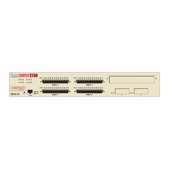
- Page 1 2E43-51/2E43-51R SmartSwitch 2100 LINK 1 LINK 1 2E43-51 RESET 9032251-04 User’s Guide LINK 1 ENET 3 ENET 4 LINK 1 ENET 1 ENET 2...
-
Page 3: Fcc Notice
Only qualified personnel should perform installation procedures. Cabletron Systems reserves the right to make changes in specifications and other information contained in this document without prior notice. The reader should in all cases consult Cabletron Systems to determine whether any such changes have been made. -
Page 4: Industry Canada Notice
IMPORTANT: Before utilizing this product, carefully read this License Agreement. This document is an agreement between you, the end user, and Cabletron Systems, Inc. (“Cabletron”) that sets forth your rights and obligations with respect to the Cabletron software program (the “Program”) contained in this package. - Page 5 Government is subject to restrictions as set forth in subparagraph (c) (1) (ii) of the Rights in Technical Data and Computer Software clause at 252.227-7013. Cabletron Systems, Inc., 35 Industrial Way, Rochester, New Hampshire 03867-0505. 2E43-51/2E43-51R User’s Guide...
-
Page 6: Safety Information
Do not use optical instruments to view the laser output. The use of optical instruments to view laser output increases eye hazard. When viewing the output optical port, power must be removed from the network adapter. SAFETY INFORMATION SAFETY INFORMATION 2E43-51/2E43-51R User’s Guide watts. -
Page 7: Declaration Of Conformity
Mr. Ronald Fotino ___________________________________ Full Name Principal Compliance Engineer ___________________________________ Title Rochester, NH, USA ___________________________________ Location 2E43-51/2E43-51R User’s Guide 89/336/EEC 73/23/EEC Cabletron Systems, Inc. 35 Industrial Way PO Box 5005 Rochester, NH 03867 Mr. J. Solari Cabletron Systems Limited Nexus House, Newbury Business Park... - Page 8 Notice 2E43-51/2E43-51R User’s Guide...
-
Page 9: Table Of Contents
Installing the 2E43-51... 3-3 3.4.1 Tabletop or Shelf Installation ... 3-3 3.4.2 Rackmount Installation ... 3-4 3.4.3 Connecting Power to the Devices... 3-7 3.4.3.1 3.4.3.2 2E43-51/2E43-51R User’s Guide CONTENTS Connecting Power to the 2E43-51 ... 3-7 Connecting Power to the 2E43-51R... 3-8... - Page 10 Setting the Device Time ...5-24 5.7.7 Entering a New Screen Refresh Time...5-25 5.7.8 Setting the Screen Lockout Time ...5-25 5.7.9 Setting the Operational Mode...5-26 5.7.10 Configuring the COM Port ...5-27 5.7.11 Clearing NVRAM ...5-29 5.7.12 Enabling/Disabling IP Fragmentation ...5-30 viii 2E43-51/2E43-51R User’s Guide...
- Page 11 5.11 Device Specific Configuration Menu Screen ... 5-39 5.12 System Resources Screen ... 5-41 5.12.1 Setting the Reset Peak Switch Utilization ... 5-43 5.13 High Speed Interface Configuration Menu Screen ... 5-44 5.14 High Speed Interface Configuration Screen ... 5-46 5.14.1 Configuring an FE-100FX or FE-100F3 ...
- Page 12 FE-100F3 ... B-3 APPENDIX C OPTIONAL INSTALLATIONS AND MODE SWITCH BANK SETTINGS Required Tools... C-1 Removing the Chassis Cover ... C-2 C.2.1 Setting the Mode Switch ... C-4 Installing Optional Fast Ethernet Interface Modules ... C-7 INDEX 2E43-51/2E43-51R User’s Guide...
-
Page 13: Chapter 1 Introduction
NOTE applies to both the 2E43-51 and the 2E43-51R SmartSwitch 2100 devices. Unless the information pertains only to the 2E43-51 or the 2E43-51R, the device is referred to as either the “2E43-51” or the “device”. STRUCTURE OF THIS GUIDE This guide is organized as follows: Chapter 1, Introduction, outlines the contents of this manual and briefly... - Page 14 Chapter 1: Introduction Chapter Local Management, describes how to access and use Local Management to configure and manage the 2E43-51. Appendix A, Specifications, contains information on functionality and operating specifications, connector pinouts, environmental requirements, and physical properties. Appendix FE-100TX, FE-100FX, and FE-100F3 contains information about FE-100TX pinouts and information concerning cable types used with the FE-100FX and FE-100F3.
-
Page 15: Link
Asynchronous Transfer Mode (ATM), Fiber Distributed Data Interface (FDDI), and Wide Area Network (WAN). The 2E43-51 may be used as a tabletop unit or can be installed in a standard 19-inch rack using the supplied rack mounting hardware. -
Page 16: Connectivity
Auto-Negotiation feature targets the maximum capabilities that can be reached between the two devices. For example, an FE-100TX Fast Ethernet Interface Module in a 2E43-51 can adjust to 100 Mbps when the device on the other end of the connection can also adjust to 100 Mbps. If the device on the other end of the connection can only operate at 10 Mbps, then the FE-100TX simply adjusts to 10 Mbps operation. -
Page 17: Smarttrunk
IP Address Discovery (RAD) checks the 2E43-51 for an IP address. If one has not yet been assigned (2E43-51 IP address set to 0.0.0.0), RAD checks to see if any of the 2E43-51 interfaces have a link. If so, RAD sends out Reverse Address Resolution Protocol (RARP) and BootP requests to obtain an IP address from a BootP server on the network. -
Page 18: Management
SNMP compliant Network Management Software. Local Management provides the ability to manage the 2E43-51 and any of the optional Fast Ethernet Interface Modules installed in ports 5 and 6, and the optional High Speed Interface Module (HSIM). -
Page 19: Year 2000 Compliant
1.3.9 Year 2000 Compliant The 2E43-51 has an internal clock that can maintain the current time and date beyond the year 1999. 1.3.10 LANVIEW Diagnostic LEDs LANVIEW diagnostic LEDs serve as an important troubleshooting aid by providing an easy way to observe the status of individual ports and overall network operations. -
Page 20: High Speed Interface Modules
High Speed Interface Modules High Speed Interface Modules (HSIMs) are available from Cabletron Systems for additional connectivity to various networking technologies. The HSIMs available for the 2E43-51 are listed in the Release Notes shipped with the 2E43-51. DOCUMENT CONVENTIONS The following conventions are used throughout this document: Note symbol. -
Page 21: Getting Help
Cabletron Systems Technical Writing Department via the following email address: TechWriting@cabletron.com Make sure to include the document Part Number in the email message. Before calling the Cabletron Systems Global Call Center, have the following information ready: • Your Cabletron Systems service contract number •... -
Page 22: Related Manuals
These manuals can be obtained from the World Wide Web in Adobe Acrobat Portable Document Format (PDF) at the following site: http://www.cabletron.com/ All documentation for the Cabletron Systems SecureFast VLAN NOTE Manager software is contained on the VLAN Manager CD-ROM. -
Page 23: Chapter 2 Network Requirements
Cabletron Systems World Wide Web site: http://www.cabletron.com/ SmartTrunk To connect the 2E43-51 into a network so that it can take advantage of the SmartTrunk feature, there are certain rules concerning port connections and configurations that must be followed for proper operation. Refer to the Cabletron Systems SmartTrunk User’s Guide for additional... -
Page 24: 100Base-Tx Network
Chapter 2: Network Requirements 100BASE-TX NETWORK The 2E43-51, with an FE-100TX installed in slots 5 and/or 6, provides an RJ45 connection that supports UTP cabling, which has an impedance of 85 to 111 ohms. The device at the other end of the twisted pair segment must meet IEEE 802.3u 100BASE-TX Fast Ethernet network... -
Page 25: Chapter 3 Installation
• Required Tools (Section • Unpacking the 2E43-51 • Installing Options • Installing the 2E43-51 (on a shelf or tabletop, or into a standard rack) (Section 3.4) • Connecting to the Network • Completing the Installation REQUIRED TOOLS A Phillips screwdriver is required to install the 2E43-51 in a rack. -
Page 26: Unpacking The 2E43-51
Chapter 3: Installation UNPACKING THE 2E43-51 To unpack the 2E43-51 and verify the contents of the shipment, proceed as follows: Open the carton and remove the packing material protecting the 2E43-51. Verify the contents of the carton as listed in... -
Page 27: Installing The 2E43-51
Appendix C instructions for the HSIMs are in the associated HSIM user’s guide. INSTALLING THE 2E43-51 The 2E43-51 may be installed on a tabletop, shelf, or in a 19-inch rack. Section 3.4.1 describes a tabletop or shelf installation, and describes the rackmount installation. -
Page 28: Rackmount Installation
Figure 3-1 Tabletop or Shelf Installation 3.4.2 Rackmount Installation To install the 2E43-51 in a 19-inch rack, the device is shipped with a rackmount kit containing the rackmount brackets, mounting screws, and a strain-relief bracket for cable management. Guidelines for the Rackmount Installation... - Page 29 Rack mounting the 2E43-51 (attaching the mounting brackets and fastening the 2E43-51 to the rack) Attaching the Strain-Relief Bracket Attach the strain-relief bracket to the front of the 2E43-51 as follows: Locate the strain-relief bracket and four 8-32 x 5/16-inch pan-head screws in the rackmount kit.
- Page 30 Chapter 3: Installation Rack Mounting the 2E43-51 Proceed as follows to install the 2E43-51 into a 19-inch rack. Remove and discard the four cover screws (two from each side) located along the front edges of each side of the 2E43-51.
-
Page 31: Connecting Power To The Devices
3.4.3.1 Connecting Power to the 2E43-51 To connect the 2E43-51 to a power source, proceed as follows: Plug the power cord into a grounded wall outlet. The PWR LED turns on (green) and the CPU LED turns on (green) briefly. -
Page 32: Connecting Power To The 2E43-51R
Check the power cord connections and the power source. If there are no problems with the power cord connections or power source and the PWR LED is still not green, contact the Cabletron Systems Global Call Center. Refer to Section 1.6 for details. -
Page 33: Connecting To The Network
CONNECTING TO THE NETWORK This section provides the procedures for connecting UTP and fiber optic segments from the network or other devices to the 2E43-51. If the 2E43-51 is being installed in a network using NOTE SmartTrunking, there are rules concerning the network cable and port configurations that must be followed for... - Page 34 Figure 3-7 Connection Using the RJ21 Angle Adapter 3-10 or, if using the RJ21 angle adapter E N E T 4 E N E T 2 Screw RJ21 E N E T 4 E N E T 2 Screw RJ21Right-Angled Connector 2E43-51/2E43-51R User’s Guide 2251-10 22511-73...
-
Page 35: Connecting A Utp Segment To The Fe-100Tx
Verify that a link exists by checking that the LINK LED on the 2E43-51 for that port is on (solid green). If the LINK LED is off, perform the following steps until it is on: Verify that the 10BASE-T device at the other end of the twisted pair segment is on and connected to the segment. - Page 36 4. NC 8. NC Figure 3-8 FE-100TX Crossover Switch A schematic of a crossover cable is shown in not cross over, use the switch on the FE-100TX to internally cross over the RJ45 port. NOTE: RX+/RX– and TX+/TX– must share a common color pair.
- Page 37 Make sure that the twisted pair connection meets the cable specifications outlined in Confirm that the crossover switch is in the correct position. If a Link is not established, contact the Cabletron Systems the Global Call Center. Refer to Section 1.6 2E43-51/2E43-51R User’s Guide...
-
Page 38: Connecting A Fiber Optic Segment To The Fe-100Fx And Fe-100F3
FE-100FX and FE-100F3 The FE-100FX and FE-100F3 have SC style network ports. See Figure 3-11. Cabletron Systems offers optional fiber optic cables that use SC style connectors. The ST connectors are keyed to ensure proper crossover of the transmit and receive fibers. - Page 39 Link. Verify proper crossover of fiber strands between the applicable port on the 2E43-51 and the fiber optic device at the other end of the fiber optic link segment. Verify that the fiber connection meets the dB loss specifications...
-
Page 40: Completing The Installation
Secure the cables by running the cables along the strain-relief bracket and tying them to the strain-relief bracket using cable ties. The 2E43-51 is now ready to be set up through Local Management. Refer to Chapter access and use Local Management to configure the 2E43-51. -
Page 41: Troubleshooting
Troubleshooting network and 2E43-51 operational problems • Using the RESET button USING LANVIEW The 2E43-51 uses Cabletron Systems built-in visual diagnostic and status monitoring system called LANVIEW. The LANVIEW LEDs allow quick observation of the network status to aid in diagnosing network problems. Refer to... - Page 42 Blinking. Crippled. Solid. Testing. Solid. Functional. Booting. Blinks amber and green while booting. 2E43-51/2E43-51R User’s Guide Recommended Action No action. 1. Ensure that the power cords are plugged in correctly and that there is power at the power source.
- Page 43 1 – 4 and Ports 5 and 6 Green Amber LINK Amber Ports of ENET 1 – 4 2E43-51/2E43-51R User’s Guide State No link. No activity. Port enabled or disabled. Blinking. Port disabled. Flashing. Port enabled, activity. Diagnostic failure. Port enabled, and no activity.
-
Page 44: Fe-100Tx Led
A link exists if the associated port (5 or 6) RX LED is on. NOTE Table 4-2 10/100 LED Indications When RX LED Is On Color 10/100 Green FE-100TX Figure 4-2 FE-100TX LED Indication FE-100TX is operating at 10 Mbps. FE-100TX is operating at 100 Mbps. 2E43-51/2E43-51R User’s Guide 2251-41... - Page 45 NOTE Table 4-3 10/100 LED Indications When RX LED Is Off Color 10/100 Green 2E43-51/2E43-51R User’s Guide Indication No Link or no cable attached. FE-100TX forced to 10 Mbps operation, or is manually set to “auto-negotiate” mode. No Link or no cable attached. FE-100TX is forced to 100 Mbps operation.
-
Page 46: Troubleshooting Checklist
Chapter 4: Troubleshooting TROUBLESHOOTING CHECKLIST If the 2E43-51 is not working properly, refer to of possible problems, causes, and recommended actions to resolve the problem. Table 4-4 Troubleshooting Checklist Problem Possible Cause All LEDs are OFF. Loss of power. Installed improperly. -
Page 47: Using The Reset Button
CAUTION downtime of up to two minutes will result from this action. 2E43-51 To reset the 2E43-51 processor, press and release the RESET button. The 2E43-51 goes through a reset process for approximately 45 seconds. 2E43-51/2E43-51R User’s Guide Figure 4-3... - Page 48 Chapter 4: Troubleshooting 2E43-51/2E43-51R User’s Guide...
-
Page 49: Chapter 5 Local Management
Local Management. It also explains how to use the Local Management screens and commands. OVERVIEW Local Management for the 2E43-51 consists of a series of screens that allow the management of the 2E43-51 and its attached segments. The screens allow the user to do the following tasks: •... -
Page 50: Local Management Keyboard Conventions
Management increment field. For example, “Press [–]” means to press the minus sign key. The DEL (Delete) key removes characters from a Local Management field. For example, “Press DEL” means to press the Delete key. 2E43-51/2E43-51R User’s Guide Table 5-1 explains... -
Page 51: Management Terminal Setup
A Digital Equipment Corporation VT100 type terminal • A VT type terminal running emulation programs for the Digital Equipment Corporation VT100 series • A remote VT100 type terminal via a modem connection • In-band via a Telnet connection 2E43-51/2E43-51R User’s Guide Management Terminal Setup... -
Page 52: Console Cable Connection
Chapter 5: Local Management 5.3.1 Console Cable Connection Use the Console Cable Kit provided with the 2E43-51 to attach the management terminal to the 2E43-51 COM port as shown in Connect an IBM PC or compatible device, running the VT terminal... -
Page 53: Management Terminal Setup Parameters
Auto Answerback -> Keyboard Setup Menu Keys -> Auto Repeat -> Keyclick -> Margin Bell -> Warning Bell -> 2E43-51/2E43-51R User’s Guide Management Terminal Setup Table 5-2 VT Terminal Setup 80 Columns Interpret Controls No Auto Wrap Jump Scroll Cursor... -
Page 54: Telnet Connections
Chapter 5: Local Management 5.3.3 Telnet Connections Once the 2E43-51 has a valid IP address, the user can establish a Telnet session with Local Management from any TCP/IP based node on the network. Telnet connections to the 2E43-51 require the community name passwords assigned at the SNMP Community Names screen of the 2E43-51. -
Page 55: Monitoring An Uninterruptible Power Supply
2E43-51 COM port to the UPS can be made to monitor the power status of the UPS. To use the COM port for this purpose, it must be reconfigured... -
Page 56: Accessing Local Management
Access to Local Management is controlled through the Local Management Password screen made to the 2E43-51 the Local Management Password screen displays. Before continuing, the user must enter a password (community name) which is compared to the previously stored passwords. The level of access allowed the user depends on the password. -
Page 57: Navigating Local Management Screens
The 2E4X-27 Local Management application consists of a series of menu screens. Navigate through Local Management by selecting items from the menu screens. The 2E43-51 supports three modes of switch operation. The switching modes are as follows: • 802.1D Switching (traditional switching) •... - Page 58 High Speed Interface Switch Statistics Configuration Interface Statistics Flash Download RMON Statistics Repeater Statistics Broadcast Suppression 802.1Q VLAN Configuration Repeater Configuration Menu 2E43-51/2E43-51R User’s Guide Fast Ethernet Interfaces HSIM Device Level Security Configuration Port Level Security Configuration 22514-43 Fast Ethernet Interfaces...
-
Page 59: Selecting Local Management Menu Screen Items
Using the RETURN Command To exit LM using the RETURN command, proceed as follows: Use the arrow keys to highlight the RETURN command at the bottom of the Local Management screen. 2E43-51/2E43-51R User’s Guide Accessing Local Management General Configuration SNMP Community Names... - Page 60 ESC twice. This exit method does not warn about unsaved changes and all unsaved changes are lost. Exit from 2E43-51 Local Management by repeating steps 1 and 2 until the Device Menu screen displays. To end the LM session, use the arrow keys to highlight the RETURN command at the bottom of the Device Menu screen.
-
Page 61: Device Menu Screen
The Device Menu screen is the access point for all Local Management screens. Figure 5-7 shows the Device Menu screen. Event Message Line Device Name: 2E43-51 Figure 5-7 Device Menu Screen If the terminal is idle for several minutes, the Local NOTE Management Password screen redisplays and the session ends 2E43-51/2E43-51R User’s Guide... -
Page 62: Device Configuration
DEVICE CONFIGURATION The Device Configuration screen provides access to the Local Management screens that are used to configure the 2E43-51 and also to the Device Specific Configuration Menu screen. The Device Specific Configuration Menu screen provides access to the screens that allow the user to check the 2E43-51 resources and set operating parameters specific... -
Page 63: Device Configuration Menu Screen
The Device Configuration Menu screen, Local Management screens. These screens allow the user to configure and monitor operating parameters, modify SNMP community names, set SNMP traps, configure switch parameters and configure 2E43-51 ports. The following menu items on the Device Configuration Menu NOTE... - Page 64 The following briefly explains each screen accessible from the Device Configuration Menu screen: GENERAL CONFIGURATION The General Configuration screen allows the user to monitor and configure operating parameters for the 2E43-51. For details, refer Section 5.7. SNMP COMMUNITY NAMES The SNMP Community Names screen allows the user to enter new, change, or review the community names used as access passwords for device management operation.
-
Page 65: General Configuration Screen
[NO] SAVE Figure 5-9 General Configuration Screen The following briefly explains each General Configuration screen field: MAC Address (Read-Only) Displays the physical address of the 2E43-51. 2E43-51/2E43-51R User’s Guide General Configuration Screen Figure 5-9, allows the user to set the... - Page 66 Chapter 5: Local Management IP Address (Modifiable) Displays and allows the user to set the IP address for the 2E43-51. To set the IP address, refer to Section 5.7.1. The IP address can also be set through Runtime IP Address Discovery as previously described in Section 1.3.5.
- Page 67 Displays the total time that the device has been operating. Operational Mode (Selectable) Allows the user to set the 2E43-51 so it operates as a an 802.1D switch (802.1D SWITCHING), an IEEE 802.1Q switch (802.1Q SWITCHING), or a Cabletron Systems SecureFast switch (SECURE FAST VLAN).
-
Page 68: Setting The Ip Address
IP Fragmentation (Toggle) Allows the user to enable or disable IP Fragmentation. The default setting for this is field is ENABLED. If the 2E43-51 is to be bridged to an FDDI ring, IP Fragmentation must be enabled. If IP Fragmentation is disabled, all FDDI frames that exceed the maximum Ethernet frame size are discarded. -
Page 69: Setting The Subnet Mask
Setting the Subnet Mask If the management workstation that is to receive SNMP traps from the 2E43-51 is located on a separate subnet, the subnet mask for the 2E43-51 may need to be changed from its default. To change the subnet mask from its default, perform the following steps: Use the arrow keys to highlight the Subnet Mask field. -
Page 70: Setting The Default Gateway
Setting the Default Gateway If the SNMP management station is located on a different IP subnet than the 2E43-51, a default gateway must be specified. When an SNMP Trap is generated, the 2E43-51 sends the Trap to the default gateway. To set the default gateway, perform the following steps: Use the arrow keys to highlight the Default Gateway field. -
Page 71: Setting The Tftp Gateway Ip Address
Setting the TFTP Gateway IP Address If the network TFTP server is located on a different IP subnet than the 2E43-51, a Gateway IP address should be specified. To set the TFTP Gateway IP address, perform the following steps: Use the arrow keys to highlight the TFTP Gateway IP Addr field. -
Page 72: Setting The Device Date
Chapter 5: Local Management 5.7.5 Setting the Device Date The 2E43-51 is year 2000 compliant so that the Device Date field can be set beyond the year 1999. To set the system date, perform the following steps: Use the arrow keys to highlight the Device Date field. -
Page 73: Entering A New Screen Refresh Time
“SAVED OK” displays at the top of the screen. If the entry is not valid, Local Management does not alter the current setting, but it does refresh the Screen Lockout Time field with the previous value. 2E43-51/2E43-51R User’s Guide General Configuration Screen 5-25... -
Page 74: Setting The Operational Mode
NOTE Port Based VLAN User’s Guide to configure the devices for this type of operation. If the 2E43-51 is set to SECURE FAST VLAN, refer to your SecureFast documentation set to configure the devices for this type of operation. 5-26... -
Page 75: Configuring The Com Port
Telnet connection to the device. If the device does not have a valid IP address and the COM port has been disabled or the settings changed, reset NVRAM on the 2E43-51 (refer to Section 5.7.11) to reestablish COM port communications. - Page 76 Exiting without saving causes the message “NOT SAVED -- PRESS SAVE TO KEEP CHANGES” to appear. Exiting without saving causes all edits to be lost. CAUTION Use the arrows keys to highlight the Application field. 5-28 Figure 5-13 WARNING 2E43-51/2E43-51R User’s Guide displays. 174252...
-
Page 77: Clearing Nvram
Use the SPACE bar to toggle the field to YES. Use the arrow keys to highlight SAVE at the bottom of the screen. Press ENTER. The warning screen shown in 2E43-51/2E43-51R User’s Guide General Configuration Screen Application Local Management Session... -
Page 78: Enabling/Disabling Ip Fragmentation
5.7.12 Enabling/Disabling IP Fragmentation To enable or disable IP Fragmentation, proceed as follows: If the 2E43-51 is being bridged to an FDDI ring (for example, via an optional HSIM-F6), enable IP Fragmentation. If it is CAUTION disabled, all FDDI frames that exceed the maximum Ethernet frame size are discarded. -
Page 79: Snmp Community Names Screen
Management community names. Community names act as passwords to Local/Remote Management and are agents of security access to the 2E43-51. Access to the 2E43-51 is controlled by enacting any of three different levels of security authorization (read-only, read-write, and super-user). -
Page 80: Establishing Community Names
The following explains each SNMP Community Names screen field: Community Name (Modifiable) Displays the user-defined name through which a user accesses the 2E43-51 SNMP Management. Any community name assigned here acts as a password to Local/Remote Management. Access Policy (Read-Only) Indicates the access accorded each community name. - Page 81 Exiting without saving causes a “NOT SAVED?” message to NOTE display above the SAVE command. Edits are lost if they are not saved before exiting. To exit the screen, use the arrow keys to highlight RETURN and press ENTER. 2E43-51/2E43-51R User’s Guide SNMP Community Names Screen 5-33...
-
Page 82: Snmp Traps Screen
Chapter 5: Local Management SNMP TRAPS SCREEN Since the 2E43-51 is an SNMP compliant device, it can send messages to multiple Network Management Stations to alert users of status changes. The SNMP Traps screen is shown in To access the SNMP Traps screen from the Device Configuration Menu screen, use the arrow keys to highlight the SNMP TRAPS menu item and press ENTER. -
Page 83: Configuring The Trap Table
Press ENTER. Use the arrow keys to highlight the Enable Traps field. Press the SPACE bar to choose either YES (send alarms from the 2E43-51 to the workstation), or NO (prevent alarms from being sent). Use the arrow keys to highlight the SAVE command and press ENTER. -
Page 84: Switch Configuration Screen
The Switch Configuration screen, options to make a switch operational in your network. To access the Switch Configuration screen from the Device Configuration Menu screen, use the arrow keys to highlight the SWITCH CONFIGURATION menu item and press ENTER. The Switch Configuration screen displays showing up to 7 ports, depending on if... - Page 85 None. To set the STA, refer to Age Time (Modifiable) Allows the user to set the amount of time (in seconds) that the 2E43-51 keeps an address in its switch table before discarding it. An address is automatically discarded when a valid Bridge Protocol Data Unit (BPDU) is not received from that address within the time specified in the Age Time...
-
Page 86: Setting The Sta
The Spanning Tree Algorithm (STA) setting allows the user to set the method that the switches use to decide which is the controller (Root) switch when two or more switches are in parallel. The available selections are IEEE, DEC, and NONE. -
Page 87: Setting (Enabling Or Disabling) The Port Status
SCREEN The Device Specific Configuration Menu screen, user to select one of five screens to configure ports or check system resources specific to the 2E43-51. The PORT REDIRECT FUNCTION menu item on the Device NOTE Specific Configuration Menu screen does not display if the operational mode of the device is set to 802.1Q SWITCHING. -
Page 88: System Resources
Configuration Menu screen: SYSTEM RESOURCES The System Resources screen displays the amount of FLASH memory, DRAM and NVRAM installed, indicates the amount of available memory and provides information on 2E43-51 operation. For details, refer to Section 5.12. HIGH SPEED INTERFACE CONFIGURATION The High Speed Interface Configuration screen provides access to the... -
Page 89: System Resources Screen
Section 802.1Q VLAN CONFIGURATION This menu item will only display if the 2E43-51 has been configured to operate as an 802.1Q switch as described in this menu item opens the VLAN Main Menu screen. For details about the VLAN Local Management screens, refer to the Cabletron Systems Port Based VLAN User’s Guide. - Page 90 Indicates the amount of FLASH memory installed in the 2E43-51 and how much is currently available. DRAM Installed (Read-only) Indicates the amount of DRAM installed in the 2E43-51 and how much of it is currently available. 5-42 2E43-51 LOCAL MANAGEMENT...
-
Page 91: Setting The Reset Peak Switch Utilization
NVRAM Installed (Read-only) Indicates the amount of NVRAM installed in the 2E43-51 and how much of it is currently available. Current Switch Utilization (Read-only) Shows the percentage of the device switching capacity currently being used. Peak Switch Utilization (Read-only) Shows the peak percentage of device switching capacity used, since the last reset. -
Page 92: High Speed Interface Configuration Menu Screen
Device Specific Configuration Menu screen, use the arrow keys to highlight the HIGH SPEED INTERFACE CONFIGURATION menu item and press ENTER. The High Speed Interface Configuration Menu screen displays. Event Message Line Device Name: 2E43-51 SAVE Figure 5-20 High Speed Interface Configuration Menu Screen 5-44 2E43-51 LOCAL MANAGEMENT... - Page 93 This screen also allows the user to enable or disable Auto-Negotiation and set the Advertised Ability. For details, refer to Section 5.14. HSIM Displays the types of interfaces installed in the High Speed Interface Module (HSIM) slots. The HSIM screens are described in their respective user’s guides. 2E43-51/2E43-51R User’s Guide 5-45...
-
Page 94: High Speed Interface Configuration Screen
Speed Interface Configuration Menu screen, use the arrow keys to highlight the FAST ETHERNET INTERFACES menu item and press ENTER. The High Speed Interface Configuration screen displays. Event Message Line Device Name: 2E43-51 Port Type Link Status Current Oper. Mode Desired Oper. - Page 95 5 or 6. The field toggles between 100Base-FX and 100Base-FXFD (full duplex) when an FE-100FX or FE-100F3 is installed. Section 5.14.1 FE-100FX or FE-100F3. 2E43-51/2E43-51R User’s Guide High Speed Interface Configuration Screen Figure 5-21 describes how to configure a port with an shows that there is an...
-
Page 96: Configuring An Fe-100Fx Or Fe-100F3
FE-100FX or FE-100F3 interface. 5-48 describes how to manually configure an Section 5.14.2.2 Section 5.14.1.1 provides instructions for 2E43-51/2E43-51R User’s Guide describes... -
Page 97: Setting The Fe-100Fx Or Fe-100F3 Operational Mode
Use the SPACE bar to select the desired mode. Press ENTER. If any mode other than Auto-Negotiation is selected, the port only operates in the chosen mode and Auto-Negotiation is disabled. 2E43-51/2E43-51R User’s Guide High Speed Interface Configuration Screen Section 5.14.2.1... -
Page 98: Setting The Fe-100Tx Advertised Ability
The user may also force the download of an image by changing NOTE the position of Switch 6 located inside the device. For details about setting the switch, refer to 5-50 Figure... -
Page 99: Screen Displays
Configuration Menu screen, use the arrow keys to highlight the FLASH DOWNLOAD menu item and press ENTER. The Flash Download screen displays. TFTP DOWNLOAD. WILL COMMIT TO FLASH. REBOOT IN PROGRESS... Device Name: 2E43-51 EXECUTE Figure 5-22 Flash Download Screen Download Server IP and Download File Name display only NOTE when TFTP or RUNTIME are selected in Download Method. - Page 100 Runtime. Reboot After Download (Modifiable only when RUNTIME is chosen) This field notifies the user that the 2E43-51 will reboot after the download is complete. If a Runtime Download is performed, this field toggles between YES and NO. If YES is selected, the device reboots after the download is completed.
-
Page 101: Image File Download Using Bootp
The complete TFTP Server path and file name of the new image is entered in this field. 5.15.1 Image File Download Using BootP To download a firmware image of FLASH to the 2E43-51 using BootP, proceed as follows: Use the arrow keys to highlight the Download Method field. -
Page 102: Image File Download Using Runtime
FLASH memory. 5.15.3 Image File Download Using Runtime To download a firmware image of FLASH to the 2E43-51 using Runtime, proceed as follows: Use the arrow keys to highlight the Download Method field. -
Page 103: Port Redirect Function Screen
Although all traffic from the source port (including, if desired, NOTE errored frames) is sent to the destination port, normal switching is still performed for all frames on the source port. 2E43-51/2E43-51R User’s Guide Port Redirect Function Screen Section 5.7.9,... - Page 104 5-56 2H43-51 LOCAL MANAGEMENT Port Redirect Function Firmware Revision: BOOTPROM Revision: XX.XX.XX Destination Port: Remap Errors: ============ ============ Destination Port [1] Errors [ON] PREVIOUS NEXT 2E43-51/2E43-51R User’s Guide XX.XX.XX Status [ADD] RETURN EXIT RETURN 22511_22...
-
Page 105: Displaying The Source And Destination Entries
To display the next screen, use the arrow keys to highlight NEXT. Press ENTER and the next screen of entries displays. To display the previous screen, use the arrow keys to highlight PREVIOUS. Press ENTER to view the entries in the previous screen. 2E43-51/2E43-51R User’s Guide 5-57... -
Page 106: Changing Source And Destination Ports
This screen may only be used when the device is configured to operate as an 802.1D or 802.1Q switch. Broadcast frames received above the threshold setting are dropped. 5-58 Figure 5-24, allows the user to set a 2E43-51/2E43-51R User’s Guide... - Page 107 To access the Broadcast Suppression screen from the Device Specific Configuration Menu screen, use the arrow keys to highlight the BROADCAST SUPPRESSION menu item and press ENTER. The Broadcast Suppression screen displays. Event Message Line Device Name: 2E43-51 PORT # Total RX 12345678910 12345678910...
-
Page 108: Setting The Threshold
Press the SPACE bar to select YES or NO. Use the arrows keys to highlight the SAVE command at the bottom of the screen. Press ENTER. The message “SAVED OK” displays and the Time Since Peak field is also reset. 5-60 2E43-51/2E43-51R User’s Guide... -
Page 109: Repeater Configuration Menu Screen
Device Specific Configuration Menu screen, select the REPEATER CONFIGURATION MENU item and press ENTER. The Repeater Configuration Menu screen displays. Module Type: 2E43-51 Figure 5-25 Repeater Configuration Menu Screen The following introduces each screen that is accessible from the Repeater Configuration Menu. -
Page 110: Repeater Level Security Configuration
(LockOnNext), or lock on the source address of the last frame received (LockedOnAddr). When either of the last two options are set, the switch can be set to receive or not receive frames and to send or not send traps when an intruder is detected. - Page 111 Any other address detected is considered as an intruder and the device executes the actions selected in the Action On Intruder field. 2E43-51/2E43-51R User’s Guide Repeater Level Security Configuration Table 5-4 for the ENET/repeater ENET 3 = Repeater ports 25 –...
-
Page 112: Setting The Repeater Level Security
With NoDisable set, the port is not turned off. • SendTrap/NoTrap – SendTrap causes the switch to send an SNMP trap when a port detects a security violation. With NoTrap set, no SNMP trap is sent. -
Page 113: Port Level Security Configuration Screen
To access the Port Level Security Configuration screen, use the arrow keys to highlight the PORT LEVEL SECURITY CONFIGURATION menu item on the Repeater Configuration Menu screen and press ENTER. The Port Level Security Configuration screen displays. 2E43-51/2E43-51R User’s Guide Port Level Security Configuration Screen Figure 5-27, functions... - Page 114 Chapter 5: Local Management Event Message Line Module Type: 2E43-51 Po rt State [LockOnNext] [Secure] Unlocked] [NonSecure] [ [LockedOnAddr] [DisablePort] [SendTrap] [Secure] [Unlocked] [NonSecure] [Unlocked] [NonSecure] [Unlocked] [NonSecure] [Unlocked] [NonSecure] [Unlocked] [NonSecure] [Unlocked] [NonSecure] [Unlocked] [NonSecure] [Unlocked] [NonSecure] [Unlocked] [NonSecure] INTERFACE #: [1] Figure 5-27 Port Level Security Configuration Screen...
- Page 115 With NoDisable set, the port is not turned off. • SendTrap/NoTrap – SendTrap causes the switch to send an SNMP trap when a port detects a security violation. With NoTrap set, no SNMP trap is sent.
-
Page 116: Setting The Port Level Security
To change the setting to NoTrap, press the SPACE bar to toggle the setting. If the security state selected is LockedOnAddr, use the arrow keys to highlight the Secure Address field for the port. Otherwise go to step 13. Enter the address to lock on. 5-68 2E43-51/2E43-51R User’s Guide... -
Page 117: Device Statistics Menu Screen
DEVICE STATISTICS MENU SCREEN The Device Statistics Menu screen, screens that allow the user to obtain switch statistics about frame traffic through each interface and view operating statistics about each port. The SWITCH STATISTICS menu item on the Device Statistics... -
Page 118: Switch Statistics
For details, refer to Section 5.23. RMON STATISTICS The RMON Statistics screen displays all the statistics gathered by the embedded RMON agent built-in to the 2E43-51. For details, refer to Section 5.24. 5-70 2E43-51 LOCAL MANAGEMENT... -
Page 119: Repeater Statistics
The Switch Statistics screen, received, transmitted, filtered, and forwarded by each port. To access the Switch Statistics screen from the Device Statistics Menu screen, use the arrow keys to highlight the SWITCH STATISTICS menu item and press ENTER. The Switch Statistics screen displays. - Page 120 ENTER. 5-72 Table 5-6 shows the port organization. Table 5-6 Port Organization Fast Ethernet Slot 5 = Port 5 Fast Ethernet Slot 6 = Port 6 HSIM Slot = Port 7 2E43-51/2E43-51R User’s Guide...
-
Page 121: Interface Statistics Screen
INTERFACE STATISTICS SCREEN The Interface Statistics screen, statistics for all of the 2E43-51 interfaces (ENET 1 – ENET 4, and Fast Ethernet Interface Modules) with the exception of an installed HSIM. Cabletron Systems HSIMs gather their own statistics, and may... - Page 122 This field may increment because it was in an initialization phase and not ready to forward packets, the switch needed to free up buffer space, or the switch was being overutilized.
- Page 123 The OutDiscards field displays the total number of outbound packets that were discarded, even though the packets contained no errors. This field may increment, because the switch needed to free up buffer space, or the switch was being overutilized. OutErrors (Read-Only) This field displays the total number of outbound packets discarded...
-
Page 124: Displaying Interface Statistics
To reset all the statistics counters of the selected interface to zero, perform the following steps: Use the arrow keys to highlight the CLEAR COUNTERS field. Press ENTER, the counters for the selected interface are reset to zero. 5-76 Section 5.23.2. 2E43-51/2E43-51R User’s Guide Section 5.23.1. -
Page 125: Rmon Statistics Screen
The following definitions explain each field of the RMON Statistics screen: RMON Index (Read-only) This field displays the current Ethernet interface for which statistics are being shown. The 2E43-51 has an embedded RMON agent that gathers statistics for each interface on the module. 2E43-51/2E43-51R User’s Guide RMON Statistics Screen... - Page 126 Drop Events (Read-only) This field displays the total number of times that the RMON agent was forced to discard packets due to the lack of available switch resources. The Drop Events field does not display the number of packets NOTE dropped, it only displays the number of times that the RMON agent was forced to discard packets.
- Page 127 64 Octets (Read-only) Displays the total number of packets including bad packets, received that were 64 bytes in length (excluding framing bits, but including FCS bytes). 2E43-51/2E43-51R User’s Guide RMON Statistics Screen 5-79...
-
Page 128: Displaying Rmon Statistics
Use the arrow keys to highlight the Index [nn] field at the bottom of the screen. Press the SPACE bar to increment (or press the DEL [delete] key to decrement) the index number. 5-80 Section Section 5.24.2. 2E43-51/2E43-51R User’s Guide 5.24.1. -
Page 129: Using The Clear Counters Command
To access the Repeater Statistics screen, use the arrow keys to highlight the REPEATER STATISTICS menu item on the Device Statistics Menu screen and press ENTER. The Repeater Statistics screen displays. Event Message Line Device Name: 2E43-51 Bytes Received: Frames received: Total Errors:... - Page 130 Displays the number of packets with bad Cyclic Redundancy Checks (CRC) received from the network. The CRC is a 4-byte field in the data packet that ensures that the data that is received is the same as the data that was originally sent. 5-82 2E43-51/2E43-51R User’s Guide...
- Page 131 This command is used to select a port to view its statistics and those of its associated Network. For details, refer to Section 5.25.1. CLEAR COUNTERS (Command) This command sets all statistics counters to zero. For details on how to use this command, refer to Section 5.25.2. 2E43-51/2E43-51R User’s Guide 5-83...
-
Page 132: Displaying Repeater Statistics
To reset all the statistics counters of the selected port to zero, perform the following steps: Use the arrow keys to highlight the CLEAR COUNTERS command field at the bottom of the screen. Press ENTER, the counters for the selected port are reset to zero. 5-84 2E43-51/2E43-51R User’s Guide... -
Page 133: Network Tools
Built-in Commands – Allow the user to access and manage network devices. The commands are arp, bridge, defroute, netstat, ping, reset, show, traceroute, soft-reset, telnet, link_trap, and atm_stp_state. 2E43-51/2E43-51R User’s Guide shows the Network Tools Help screen. defroute reset link_trap... -
Page 134: Built-In Commands
The arp command provides access to the ARP (Address Resolution Protocol) cache, enabling you to view cache data, delete entries, or add a static route. Super-user access is required to delete an entry or add a static route. 2E43-51/2E43-51R User’s Guide... -
Page 135: Mac Address
# (30) -> arp -d 1 122.144.52.68 -> arp -s 1 22.44.2.3 00:00:0e:03:1d:3c -> arp -f 2E43-51/2E43-51R User’s Guide Each ARP cache entry lists the network interface that the device is connected to, the device’s network address or IP address, the device’s physical address or MAC address, and... - Page 136 [interface number] [IP address] The defroute command allows the user, in the syntax order shown above, to view, set, or delete the default IP route to a managed device through the specified interface. Not Applicable 2E43-51/2E43-51R User’s Guide 05141-68 05141-69...
- Page 137 Description: Options: Example: -> ping 122.144.40.10 122.144.40.10 is alive 2E43-51/2E43-51R User’s Guide netstat [option] The netstat command provides a display of general network statistics for the managed device. The netstat command must be used with one of the two display options.
- Page 138 ARP caches, route tables, FIB tables, server tables, and interface tables. The number of valid entries in the table will be displayed at the end of the table display. Not Applicable 2E43-51/2E43-51R User’s Guide 17421-45...
- Page 139 Syntax: Description: Options: Example: -> traceroute 122.144.11.52 # next-hop[0] : 122.144.60.45 # next-hop[1] : 122.144.8.113 # next-hop[2] : 122.144.61.45 # 122.144.11.52 is alive : 3 hops away. 2E43-51/2E43-51R User’s Guide OperStatus Forwarding 1500 enabled enabled disabled 1500 disabled PhysicalAddress NetworkAddress 123.456.40.1...
- Page 140 The user must specify the remote host using its IP address. The [IP address] field is mandatory. If no Port number is specified, telnet will attempt to contact the host at the default port. Not Applicable 2E43-51/2E43-51R User’s Guide 22511-76...
- Page 141 Link traps have been DISABLED on all ports (1-24) -> link_trap status 3 Link traps are ENABLED on port 3 2E43-51/2E43-51R User’s Guide link_trap [enable/disable/status] [PORT/all] The link_trap command allows link traps to be enabled or disabled when specifying a single port, or simultaneously when specifying “all”...
-
Page 142: Special Commands
Chapter 5: Local Management atm_stp_state: The atm_stp_state command is only available if an NOTE HSIM-A6DP is installed in the device (e.g.,2E43-51). This command allows the user to enable, disable, or check the current status of the Spanning Tree Algorithm on all ATM interfaces. - Page 143 Network Tools Example: -> done Connection closed 05141-72 2E43-51/2E43-51R User’s Guide 5-95...
- Page 144 Chapter 5: Local Management 5-96 2E43-51/2E43-51R User’s Guide...
-
Page 145: A.3 Electrical Specifications
This appendix provides operating specifications for the 2E43-51 and 2E43-51R. Cabletron Systems reserves the right to change these specifications at any time without notice. DEVICE SPECIFICATIONS Processor: Dynamic Random Access Memory (DRAM): FLASH Memory: PHYSICAL PROPERTIES Dimensions: Weight (Unit) 2E43-51:... -
Page 146: A.4 Environmental Requirements
RJ21 type connectors. Each connector provides connection for 12 twisted pair ports. Slots accept three types of optional Fast Ethernet Interface Modules: FE100-TX, FE100-FX, and FE100-F3. Slot accepts optional High Speed Interface Modules. Input/Output Output Output Input Input Output Input 2E43-51/2E43-51R User’s Guide... -
Page 147: A.7 Regulatory Compliance
REGULATORY COMPLIANCE This equipment meets the following safety and electromagnetic compatibility (EMC) requirements: Safety 2E43-51/2E43-51R User’s Guide Regulatory Compliance UL 1950, CSA C22.2 No. 950, EN 60950, IEC 950, and 73/23/EEC. FCC Part 15, EN 55022, CSA C108.8, EN 50082-1, AS/NZS 3548,... - Page 148 Appendix A: Specifications 2E43-51/2E43-51R User’s Guide...
-
Page 149: B.1 Fe-100Tx
FE-100TX, FE-100FX, AND FE-100F3 The 2E43-51 supports three Fast Ethernet Interface Modules: • FE-100TX (Section • FE-100FX (Section • FE-100F3 (Section This appendix provides the specifications for these modules. FE-100TX The FE-100TX uses an RJ45 connector supporting Category 5 Unshielded Twisted Pair (UTP), which has an impedance of 85 to 111 ohms, and Shielded Twisted Pair (STP) cabling. -
Page 150: B.2 Fe-100Fx
Figure B-2 uses an SC style connector that Figure B-2 FE-100FX Table B-1 Transmitter Power Worst Case Budget 6.0 dB 9.0 dB 15.0 dB 2E43-51/2E43-51R User’s Guide 2251-40 Typical Budget 9.0 dB 12.0 dB 18.0 dB... -
Page 151: B.3 Fe-100F3
If power levels are being measured with an average power meter, add 3 dB to the measurement to compare the measured values to the values listed above. 2E43-51/2E43-51R User’s Guide Figure B-3 uses an SC style connector that Figure B-3 FE-100F3... - Page 152 Appendix B: FE-100TX, FE-100FX, and FE-100F3 Specifications 2E43-51/2E43-51R User’s Guide...
-
Page 153: C.1 Required Tools
• Installing Optional Fast Ethernet Interface Modules REQUIRED TOOLS You need the following tools to perform the procedures provided in this appendix: • Antistatic wrist strap (provided) • Phillips screwdriver 2E43-51/2E43-51R User’s Guide APPENDIX C C.1) (Section C.2) (Section C.3) -
Page 154: Removing The Chassis Cover
Appendix C: Optional Installations and Mode Switch Bank Settings REMOVING THE CHASSIS COVER This section describes how to remove the 2E43-51 chassis cover. DO NOT REMOVE THE COVER FROM THE 2E43-51 WHILE POWER IS APPLIED TO THE UNIT. HAZARDOUS VOLTAGES ARE PRESENT AND COULD CAUSE PERSONAL INJURY AND/OR DAMAGE THE UNIT. - Page 155 To remove the chassis cover, proceed as follows: Disconnect the 2E43-51 from the network as follows: For the 2E43-51, unplug the power cord from the rear of the chassis. For the 2E43-51R, unplug both power cords from the rear of the chassis.
-
Page 156: Setting The Mode Switch
Appendix C: Optional Installations and Mode Switch Bank Settings If the 2E43-51 is rack mounted, remove it from the rack and remove the rackmount brackets (refer to and Mode Switch Bank Use a Phillips screwdriver to remove the screws attaching the cover to the chassis. - Page 157 BootP server or the TFTP server until the RESET button on the 2E43-51 is pressed. Once the RESET button is pressed, the 2E43-51 will reset after one minute and load the image stored in FLASH memory. 2E43-51/2E43-51R User’s Guide...
- Page 158 NVRAM on the next power-up. All user-entered parameters, such as the IP address, device names, etc., are reset to the factory default settings. Once the 2E43-51 resets, you can either use the factory default settings or reenter your own parameters.
-
Page 159: Installing Optional Fast Ethernet Interface Modules
7. TOP VIEW WITHOUT COVER Primary Power Supply FRONT PANEL Primary Power Supply FRONT PANEL Figure C-3 Fast Ethernet Interface Module Connector Location 2E43-51/2E43-51R User’s Guide Redundant Power Supply (2E43-51R only) Connectors Optional Fast Ethernet Interface Modules Redundant Power... - Page 160 The Fast Ethernet Interface Module and the 2E43-51 are sensitive to static discharges. Use an antistatic wrist strap and observe all static precautions during this procedure. Failure to CAUTION do so could damage the module or the 2E43-51.
- Page 161 2E43-51, remove the rubber plug on the module before CAUTION proceeding. Figure C-5. Gently pull the faceplate of the 2E43-51 forward to allow room for the Fast Ethernet Interface Modules to be aligned over the connector. In the following step, take care when inserting the Fast Ethernet...
- Page 162 Appendix C: Optional Installations and Mode Switch Bank Settings Carefully lower the Fast Ethernet Interface Module onto the standoffs while inserting the module connector into the associated Motherboard Connector. Figure C-5 Installing the Fast Ethernet Interface Module Press down firmly on the Fast Ethernet Interface Module until the pins slide all the way into the Motherboard Connector.
- Page 163 CLEAR 5-83 COM port 5-27 pin assignments A-2 Command Set 5-85 Connecting to the network 3-9 Crossover switch B-1 2E43-51/2E43-51R User’s Guide INDEX Default gateway 5-18, 5-22 Device Configuration screen 5-15 Device date 5-18 Device Menu screen 5-13 Device Specific Configuration Menu...
- Page 164 1-6 Management Terminal COM port connection of 5-3, 5-4 setup of 5-3, 5-5 Mode Switch setting C-4 Port Redirect Function screen destination port 5-57 source port 5-57 Network connection FE-100FX/FE-100F3 3-14 FX-100TX 3-11 Network Connections 3-9 2E43-51/2E43-51R User’s Guide...
- Page 165 5-67 state 5-66 Port Level Security Configuration screen 5-65 Port Redirect Function screen destination port 5-56 errors 5-57 2E43-51/2E43-51R User’s Guide remap errors 5-56 source port 5-56 status 5-57 Regulatory Compliance A-3 Related manuals 1-10 Repeater Configuration Menu screen 5-61...
- Page 166 5-86 Special Commands, Network Tools 5-94 Specifications A-1 Standards compatibility 1-6 Subnet mask 5-18, 5-21 Switch address 5-37 Switch Configuration screen 5-36 age time 5-38 MAC address 5-37 number of ports 5-37 port # 5-37 2E43-51/2E43-51R User’s Guide...
- Page 167 Telnet connections 5-6 TFTP gateway Ip addr 5-52 Trap table configuration 5-35 Traps enable 5-35 Troubleshooting 4-1 checklist 4-6 Uninterruptible Power Supply COM configuration for 5-7 connection of 5-7 Unpacking 3-2 VLAN configuration of 5-41 2E43-51/2E43-51R User’s Guide Index Index-5...
- Page 168 Index Index-6 2E43-51/2E43-51R User’s Guide...
Need help?
Do you have a question about the 2E43-51 and is the answer not in the manual?
Questions and answers