Table of Contents
Advertisement
Quick Links
Advertisement
Table of Contents

Related Manuals for Cabletron Systems FlowPoint 2100 12


Summary of Contents for Cabletron Systems FlowPoint 2100 12
- Page 1 SmartSwitch 9000 9E428-12/36 and 9E429-12/36 User’s Guide 903number...
- Page 3 Printed in the United States of America Order Number: 9032022-01 February 1998 LANVIEW is a registered trademark, and SmartSwitch is a trademark of Cabletron Systems, Inc. CompuServe is a registered trademark of CompuServe, Inc. i960 microprocessor is a registered trademark of Intel Corp.
-
Page 4: Fcc Notice
Notice FCC Notice This device complies with Part 15 of the FCC rules. Operation is subject to the following two conditions: (1) this device may not cause harmful interference, and (2) this device must accept any interference received, including interference that may cause undesired operation. NOTE: This equipment has been tested and found to comply with the limits for a Class A digital device, pursuant to Part 15 of the FCC rules. -
Page 5: Doc Notice
Notice DOC Notice This digital apparatus does not exceed the Class A limits for radio noise emissions from digital apparatus set out in the Radio Interference Regulations of the Canadian Department of Communications. Le présent appareil numérique n’émet pas de bruits radioélectriques dépassant les limites applicables aux appareils numériques de la class A prescrites dans le Règlement sur le brouillage radioélectrique édicté... -
Page 6: Declaration Of Conformity
____________________________________________________ Title Rochester, NH, USA ____________________________________________________ Location ADDENDUM 89/336/EEC 73/23/EEC Cabletron Systems, Inc. 35 Industrial Way PO Box 5005 Rochester, NH 03867 Mr. J. Solari Cabletron Systems Limited Nexus House, Newbury Business Park London Road, Newbury Berkshire RG13 2PZ, England... -
Page 7: Table Of Contents
Chapter 2 Installing the 9E428 and 9E429 Modules Unpacking the Module... 2-1 User Accessible Components ... 2-2 Setting the Module DIP Switch ... 2-3 Installing the Module in the SmartSwitch 9000 Chassis ... 2-5 The Reset Switch ... 2-7 Chapter 3 Operation ENIB ... - Page 8 Contents Chapter 5 Specifications Technical Specifications ... 5-1 CPU ... 5-1 Memory ... 5-1 Standards... 5-1 Network Interfaces ... 5-1 Safety... 5-2 Service ... 5-2 Physical ... 5-2 Dimensions ... 5-2 Weight ... 5-2 Environment ... 5-3...
-
Page 9: Chapter 1 Introduction
These modules can operate in two modes: either as a 12/36 port Ethernet traditional switch (using 802.1d standards) with a high speed backbone connection, or as a Secure Fast Switch (SFS) with 12/36 Ethernet connections. Each port can be configured to operate in the Full Duplex mode. This configuration allows each port to provide a full 20 Mbps of bandwidth for file... -
Page 10: Features
Spanning Tree, RMON, and MIB support, within a scalable RISC-Based architecture. Fast Packet Switching The 9E428-12/36 and 9E429-12/36 modules incorporate a hardware based switch design referred to as the SmartSwitch ASIC, a collection of custom ASICs designed specifically for high speed switching. Because all frame translation, address lookups, and forwarding decisions are performed in hardware, these modules can obtain a throughput performance of greater than 750K pps. - Page 11 or full duplex mode. Operating in standard Ethernet mode limits bandwidth to 10 Mbps per port, while operating in duplex mode doubles bandwidth from 10 Mbps to 20 Mbps per port. Management Information Base (MIB) Support The 9E428-12/36 and 9E429-12/36 modules provide MIB support including: •...
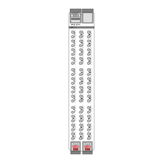
- Page 12 Introduction 10 BASE-T 10 BASE-T 9E428-12 Figure 1-1. 10 BASE-T 9E428-36 9E429-12 The 9E428-12/36 and 9E429-12/36 Modules 10 BASE-T 9E429-36...
-
Page 13: Related Manuals
• A description of any action(s) already taken to resolve the problem (e.g., changing mode switches, rebooting the unit, etc.) • The serial and revision numbers of all involved Cabletron Systems products in the network • A description of your network environment (layout, cable type, etc.) •... - Page 14 Introduction...
-
Page 15: Chapter 2 Installing The 9E428 And 9E429 Modules
2. Remove the module from the plastic bag. Observe all precautions to prevent damage from Electrostatic Discharge (ESD). 3. Carefully examine the module, checking for damage. If any damage exists, DO NOT install the module. Contact Cabletron Systems Technical Support immediately. Chapter 2... -
Page 16: User Accessible Components
User Accessible Components Figure 2-1 shows the various components that can be accessed by users. These consist of an eight-position dip switch (explained in the next section), replaceable PROMs, and sockets for memory and flash upgrades. These will be used for future upgrades. -
Page 17: Setting The Module Dip Switch
Installing the 9E428 and 9E429 Modules Setting the Module DIP Switch The DIP switch on the 9E428 and 9E429 Modules (Figure 2-1 and Figure 2-2), is an eight-switch DIP located near the bottom left corner of the module. Each switch is set according to the functions described in Table 2-1. - Page 18 Reserved Reserved Reserved Reserved Caution: Do not toggle Switch 8 unless you intend to reset the user configured passwords to the factory default settings. CAUTION Caution: Do not toggle Switch 7 unless you intend to reset the user entered parameters to the factory default settings.
-
Page 19: Installing The Module In The Smartswitch 9000 Chassis
Installing the Module in the SmartSwitch 9000 Chassis To install the 9E428-12/36 and the 9E429-12/36 modules in the SmartSwitch 9000 chassis, follow the steps below: 1. Remove the blank panel covering the slot in which the module will be mounted. All other slots must be covered to ensure proper airflow and cooling. - Page 20 Installing the 9E428 and 9E429 Modules Metal Back-Panel Warning: Ensure that the circuit card is between the card guides. Lock down the top and bottom plastic tabs at the same time, applying even pressure. Jack for ESD Wrist Strap Module Module Guides Figure 2-3.
-
Page 21: The Reset Switch
The Reset Switch The Reset switch is located on the front panel, under the top plastic tab as shown in Figure 2-4. It serves three functions: resetting the i960 processor, shutting down the module, or restarting the module. • To reset the i960 processor, press the reset switch twice within three seconds. - Page 22 Installing the 9E428 and 9E429 Modules...
-
Page 23: Chapter 3 Operation
Chapter 3 Operation The 9E428-12 and the 9E429-12 modules are 13 port devices. Twenty four front panel ST connectors support 12 10BASE-FL ports, each port being a separate collision domain with the first port connecting to INB-B. The 9E428-36 and the 9E429-36 modules are 37 port devices. -
Page 24: Enib
ENI B ENI B ENI B ENI B ENI B ENI B ENI B ENI B ENI B Figure 3-1. Packet Flow for the 9E428-36 and 9E429-36 SMB 1 Diagnostic i960 Controller Processor SMB 10 DC/DC Convertor Fast Packet Switch... -
Page 25: Smartswitch Asic
SmartSwitch ASIC The SmartSwitch ASIC is a hardware-based switch design that is the key building block of the SmartSwitch 9000 hub. The SmartSwitch ASIC makes all filtering/ forwarding decisions in custom hardware as opposed to software like in traditional bridges. This custom hardware enables the SmartSwitch ASIC to process over 750K frames per second. -
Page 26: System Management Buses
Operation System Management Buses There are two management channels within the SmartSwitch 9000 system: the SMB-1 and the SMB-10. These buses provide side-band management and inter- module management communication. SMB-1 Bus The SMB-1 is a 1Mbs management bus located within the SmartSwitch 9000. This bus is utilized by all diagnostic controllers in the system including connectivity modules, power supply modules and the environmental module. -
Page 27: Dc/Dc Converter
DC/DC Converter The DC/DC converter converts the 48 VDC on the system power bus to the necessary operating voltages for its host network services module. The diagnostic controller monitors and controls the operation of the DC/DC converter. INB Interface The INB Backplane is designed to transport fixed length data blocks between modules in the SmartSwitch 9000 using an INB Time Division Multiplexing (ITDM) design. -
Page 28: Monarch/Slave Smartswitch 9000 Modules
Operation Round Robin Arbitration (Level 2) This level makes use of idle time slices. There is a token passed on every time slice to modules participating in this level of arbitration. Only one module has the token at any one time slice. If the module assigned to the next time slice is not requesting then the module with the token will be granted access if it is requesting. -
Page 29: Lanview Leds
LANVIEW LEDs The front panel LANVIEW LEDs indicate the status of the module and may be used as an aid in troubleshooting. Shown in Figure 4-1 are the LANVIEW LEDs of the 9E428-12 module. The LEDs positions and functions are the same for the 9E428-36 and the 9E429-12/36 modules. - Page 30 LANVIEW LEDs Table 4-1. System Status (SMB and CPU) LEDs (Continued) LED Color State Yellow/Green Booting Reset Red (Blinking) Failed Power off The functions of the INB Receive LEDs are listed in Table 4-2. LED Color Green Link, no activity, port enabled Green (Blinking) Link, port disabled Yellow (Flashing)
- Page 31 Fault No link, (port disabled) The functions of the Port Transmit LEDs are listed in Table 4-5. LED Color Green (Flashing) Data activity (flashing to steady on indicates rate) Yellow (Blinking) Port in standby state Red (Flashing) Collision (with collision rate) Fault No activity, port can be disabled or enabled Table 4-4.
- Page 32 LANVIEW LEDs...
-
Page 33: Technical Specifications
Specifications Technical Specifications Intel i960 RISC based microprocessor Memory 4 Mb Local RAM (expandable to 32 Mb) 4 Mb Flash Memory (expandable to 32 Mb) 2 Mb Packet RAM 16 Mb DRAM Standards IEEE 802.1D IEEE 802.3j 10BASE-FL Network Interfaces Straight through (ST) connectors Chapter 5... -
Page 34: Dimensions
Specifications Safety It is the responsibility of the person who sells the system to which the module will be a part to ensure that the total system meets allowed limits of conducted and radiated emissions. CAUTION This equipment meets the safety requirements of: UL 1950 CSA C22.2 No. -
Page 35: Environment
Environment Operating Temperature Storage Temperature Relative Humidity 5 to 40 C -30 to 90 C 5% to 95% non-condensing Specifications... - Page 36 Specifications...
Need help?
Do you have a question about the FlowPoint 2100 12 and is the answer not in the manual?
Questions and answers