Table of Contents
Advertisement
Quick Links
-7-Series AC Servo Drive
-7S/
-7W SERVOPACK with
Hardware Option Specifications
Dynamic Brake
Product Manual
SGD7S-020
SGD7W-020
MANUAL NO. SIEP S800001 73E
Basic Information on SERVOPACKs
Selecting a SERVOPACK
Selecting a Dynamic Brake Resistor
Wiring and Connecting
a Dynamic Brake Resistor
Basic Functions That Require
Setting before Operation
Maintenance
Parameter Lists
Appendices
1
2
3
4
5
6
7
8
Advertisement
Table of Contents
Troubleshooting

Subscribe to Our Youtube Channel
Related Manuals for YASKAWA Sigma-7S Series


Summary of Contents for YASKAWA Sigma-7S Series
- Page 1 -7-Series AC Servo Drive -7S/ -7W SERVOPACK with Hardware Option Specifications Dynamic Brake Product Manual SGD7S-020 SGD7W-020 Basic Information on SERVOPACKs Selecting a SERVOPACK Selecting a Dynamic Brake Resistor Wiring and Connecting a Dynamic Brake Resistor Basic Functions That Require Setting before Operation Maintenance Parameter Lists...
- Page 2 Yaskawa. No patent liability is assumed with respect to the use of the informa- tion contained herein. Moreover, because Yaskawa is constantly striving to improve its high-quality products, the information contained in this manual is sub- ject to change without notice.
-
Page 3: About This Manual
About this Manual This manual provides information on Σ-7-Series AC Servo Drives that support the dynamic brake hardware option specifications (SGD7-020). It describes the specifications of SERVOPACKs that are different from the SERVOPACKs that do not support the dynamic brake hardware option specifications. - Page 4 Continued from previous page. Σ-7W Σ-7S SERVOPACKs SERVOPACKs MECHA- Command Option MECHA- This Analog Item TROLINK-II/ Attachable TROLINK-III Manual Voltage/ -III Commu- Communica- Pulse Train INDEXER DeviceNet nications tions References Module Module References References Dynamic Brake Resistor Wiring and Con- Chapter nections Motor Stopping Methods...
-
Page 5: Related Documents
Related Documents The relationships between the documents that are related to the Servo Drives are shown in the following figure. The numbers in the figure correspond to the numbers in the table on the following pages. Refer to these documents as required. System Components Machine Controllers... - Page 6 Classification Document Name Document No. Description Describes the features and applica- Machine Controller and tion examples for combinations of Machine Controller and AC Servo Drive KAEP S800001 22 MP3000-Series Machine Control- Servo Drive lers and Σ-7-Series AC Servo Solutions Catalog General Catalog Drives.
- Page 7 Continued from previous page. Classification Document Name Document No. Description Σ-7-Series AC Servo Drive Provides detailed information for Σ-7S and Σ-7W SERVOPACK the safe usage of Σ-7-Series TOMP C710828 00 Safety Precautions SERVOPACKs. Σ-V-Series/Σ-V-Series for Large-Capacity Models/ Provides detailed information for Σ-7-Series TOBP C720829 00 the safe usage of Option Modules.
- Page 8 Continued from previous page. Classification Document Name Document No. Description Σ-7-Series AC Servo Drive Σ-7S SERVOPACK with MECHATROLINK-III SIEP S800001 28 Communications References Product Manual Σ-7-Series AC Servo Drive Σ-7S SERVOPACK with MECHATROLINK-II SIEP S800001 27 Communications References Product Manual Σ-7-Series AC Servo Drive Σ-7S SERVOPACK with Analog Voltage/Pulse Train...
- Page 9 Continued from previous page. Classification Document Name Document No. Description Σ-7-Series AC Servo Drive Σ-7S SERVOPACK with FT/EX Specification for Index- SIEP S800001 84 ing Application Product Manual Σ-7-Series AC Servo Drive Σ-7S SERVOPACK with FT/EX Specification for Track- SIEP S800001 89 ing Application Product Manual Σ-7-Series AC Servo Drive...
- Page 10 Continued from previous page. Classification Document Name Document No. Description AC Servo Drives Σ-V Series/Σ-V Series Provides details information for Large-Capacity Models/ SIEP C720829 06 required for the design and mainte- Option Module Σ-7 Series nance of a Safety Module. User’s Manual User’s Manual Safety Module...
- Page 11 Continued from previous page. Classification Document Name Document No. Description Machine Controller MP2000/MP3000 Series Describes in detail how to operate Engineering Tool SIEP C880761 03 MPE720 version 7. MPE720 Version 7 User’s Manual Σ-7-Series AC Servo Drive Describes the operating proce- Σ-7-Series Digital Operator SIEP S800001 33...
-
Page 12: Using This Manual
Using This Manual Technical Terms Used in This Manual The following terms are used in this manual. Term Meaning A Σ-7-Series Rotary Servomotor, Direct Drive Servomotor, or Linear Servomotor. Servomotor A generic term used for a Σ-7-Series Rotary Servomotor (SGM7M, SGM7J, SGM7A, SGM7P, SGM7G, or SGMMV) or a Direct Drive Servomotor (SGM7D, SGM7E, SGM7F, SGMCV, or Rotary Servomotor SGMCS). - Page 13 Notation Used in this Manual Notation for Reverse Signals The names of reverse signals (i.e., ones that are valid when low) are written with a forward slash (/) before the signal abbreviation. Notation Example BK is written as /BK. ...
- Page 14 Engineering Tools Used in This Manual This manual uses the interfaces of the SigmaWin+ for descriptions. Trademarks • QR code is a trademark of Denso Wave Inc. • MECHATROLINK is a trademark of the MECHATROLINK Members Association. • Other product names and company names are the trademarks or registered trademarks of the respective company.
-
Page 15: Safety Precautions
Safety Precautions Safety Information To prevent personal injury and equipment damage in advance, the following signal words are used to indicate safety precautions in this document. The signal words are used to classify the hazards and the degree of damage or injury that may occur if a product is used incorrectly. Information marked as shown below is important for safety. - Page 16 Safety Precautions That Must Always Be Observed General Precautions DANGER Read and understand this manual to ensure the safe usage of the product. Keep this manual in a safe, convenient place so that it can be referred to whenever necessary. Make sure that it is delivered to the final user of the product.
- Page 17 NOTICE Do not attempt to use a SERVOPACK or Servomotor that is damaged or that has missing parts. Install external emergency stop circuits that shut OFF the power supply and stops operation immediately when an error occurs. In locations with poor power supply conditions, install the necessary protective devices (such as AC reactors) to ensure that the input power is supplied within the specified voltage range.
- Page 18 NOTICE Do not hold onto the front cover or connectors when you move a SERVOPACK. There is a risk of the SERVOPACK falling. A SERVOPACK or Servomotor is a precision device. Do not drop it or subject it to strong shock. There is a risk of failure or damage.
- Page 19 NOTICE Do not install or store the product in any of the following locations. • Locations that are subject to direct sunlight • Locations that are subject to ambient temperatures that exceed product specifications • Locations that are subject to relative humidities that exceed product specifications •...
- Page 20 Whenever possible, use the Cables specified by Yaskawa. If you use any other cables, confirm the rated current and application environment of your model and use the wiring materials specified by Yaskawa or equivalent materials. Securely tighten cable connector screws and lock mechanisms.
- Page 21 Operation Precautions WARNING Before starting operation with a machine connected, change the settings of the switches and parameters to match the machine. Unexpected machine operation, failure, or personal injury may occur if operation is started before appropriate settings are made. ...
- Page 22 NOTICE When you adjust the gain during system commissioning, use a measuring instrument to monitor the torque waveform and speed waveform and confirm that there is no vibration. If a high gain causes vibration, the Servomotor will be damaged quickly. ...
- Page 23 Troubleshooting Precautions DANGER If the safety device (molded-case circuit breaker or fuse) installed in the power supply line oper- ates, remove the cause before you supply power to the SERVOPACK again. If necessary, repair or replace the SERVOPACK, check the wiring, and remove the factor that caused the safety device to operate.
- Page 24 We will update the document number of the document and issue revisions when changes are made. Any and all quality guarantees provided by Yaskawa are null and void if the customer modifies the product in any way. Yaskawa disavows any responsibility for damages or losses that are caused by modified products.
-
Page 25: Warranty
• Events for which Yaskawa is not responsible, such as natural or human-made disasters Limitations of Liability • Yaskawa shall in no event be responsible for any damage or loss of opportunity to the customer that arises due to failure of the delivered product. - Page 26 • It is the customer’s responsibility to confirm conformity with any standards, codes, or regulations that apply if the Yaskawa product is used in combination with any other products. • The customer must confirm that the Yaskawa product is suitable for the systems, machines, and equipment used by the customer.
-
Page 27: Compliance With Ul Standards, Eu Directives, And Other Safety Standards
• SGLGW* UL 1004-1 • SGLFW* Linear UL 1004-6 • SGLFW2 Servomotors (E165827) • SGLTW* Only products with derating specifications are in compliance with the UL Standards. Estimates are available for those prod- ucts. Contact your Yaskawa representative for details. xxvii... - Page 28 EU Directives Product Model EU Directives Harmonized Standards Machinery Directive EN ISO13849-1: 2015 2006/42/EC EN 55011 group 1, class A EN 61000-6-2 EMC Directive EN 61000-6-4 2014/30/EU EN 61800-3 (Category C2, Second SERVOPACKs SGD7S environment) Low Voltage Directive EN 50178 2014/35/EU EN 61800-5-1 RoHS Directive...
- Page 29 Safety Standards Product Model Safety Standards Standards EN ISO13849-1: 2015 Safety of Machinery IEC 60204-1 IEC 61508 series SERVOPACKs SGD7S Functional Safety IEC 62061 IEC 61800-5-2 IEC 61326-3-1 Safety Parameters Item Standards Performance Level IEC 61508 SIL3 Safety Integrity Level IEC 62061 SILCL3 Mission Time...
-
Page 30: Table Of Contents
Contents About this Manual ..........iii Finding Information . - Page 31 Calculating the Energy Consumption of the Dynamic Brake Resistor . . 3-14 Presenting the Required Specifications to the Resistor Manufacturer . . 3-15 Wiring and Connecting a Dynamic Brake Resistor Wiring and Connecting SERVOPACKs ....4-2 Dynamic Brake Resistor Connections .
- Page 32 Appendices Monitor Displays for the Dynamic Brake Hardware Option Specifications . . 8-2 Coasting Distance when Stopping with the Dynamic Brake . . . 8-3 Data for Coasting Distance Calculation ....8-4 8.3.1 Coasting Distance Coefficients.
- Page 33 Basic Information on SERVOPACKs This chapter provides information required to select SERVOPACKs, such as part names and SERVOPACK models. About the Dynamic Brake Hardware Option Specifications . . 1-2 1.1.1 What Is Dynamic Braking? ....1-2 1.1.2 Capabilities of SERVOPACKs That Support the Dynamic Brake Hardware Option...
-
Page 34: About The Dynamic Brake Hardware Option Specifications
1.1 About the Dynamic Brake Hardware Option Specifications 1.1.1 What Is Dynamic Braking? About the Dynamic Brake Hardware Option Specifications CAUTION Do not use the dynamic brake for any application other than an emergency stop. There is a risk of failure due to rapid deterioration of elements in the SERVOPACK and the risk of unexpected operation, machine damage, burning, or injury. -
Page 35: Interpreting The Nameplate
1.2 Interpreting the Nameplate Interpreting the Nameplate The following basic information is provided on the nameplate. SERVOPACK model Degree of protection Surrounding air temperature BTO information Order number Serial number... -
Page 36: Part Names
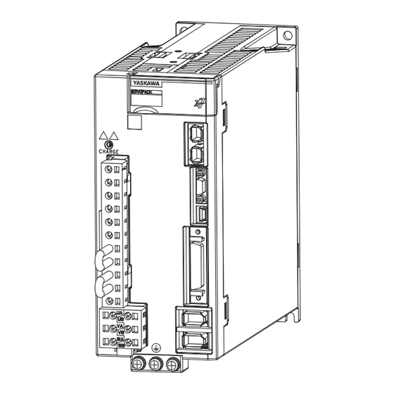
1.3 Part Names 1.3.1 SGD7S-R70A to -2R8A, SGD7S-R70F to -2R8F, and SGD7W-1R6A to -2R8A Part Names This section describes the connection terminals for an external dynamic brake resistor. All other names are the same as those for a standard SERVOPACK. Refer to the standard SERVOPACK product manual. -
Page 37: Sgd7S-470A To -780A
1.3 Part Names 1.3.3 SGD7S-470A to -780A 1.3.3 SGD7S-470A to -780A The SGD7S-470A to -780A have external dynamic brake resistor terminals on the front of the SERVOPACK next to the CHARGE indicator. • SGD7S-470A and -550A • SGD7S-590A and -780A 1.3.4 SGD7W-5R5A and -7R6A The SGD7W-5R5A and -7R6A have external dynamic brake resistor terminals on the bottom of... -
Page 38: Model Designations
1.4 Model Designations 1.4.1 Interpreting Σ-7S SERVOPACK Model Numbers Model Designations Interpreting Σ-7S SERVOPACK Model Numbers 1.4.1 SGD7S - R70 14th 1st+2nd+3rd 5th+6th 8th+9th+10th 11th+12th+13th Σ-7-Series digit digit digit digits digits digits digits Σ-7S SERVOPACKs Maximum Applicable Hardware Options 1st+2nd+3rd digits 4th digit 8th+9th+10th digits Voltage... -
Page 39: Interpreting Σ-7W Servopack Model Numbers
1.4 Model Designations 1.4.2 Interpreting Σ-7W SERVOPACK Model Numbers Interpreting Σ-7W SERVOPACK Model Numbers 1.4.2 SGD7W - 1R6 14th 1st+2nd+3rd 5th+6th 8th+9th+10th 11th+12th+13th Σ-7-Series digit digit digit digits digits digits digits Σ-7W SERVOPACKs Maximum Applicable Hardware Options 1st+2nd+3rd digits 4th digit 8th+9th+10th digits Voltage Specification... -
Page 40: Selecting A Servopack
Selecting a SERVOPACK This chapter provides information required to select SERVOPACKs, such as specifications and external dimen- sional drawings. Combinations of Servomotors and SERVOPACKs . . 2-2 2.1.1 Combinations of Rotary Servomotors and SERVOPACKs ......2-2 2.1.2 Combinations of Direct Drive Servomotors and SERVOPACKs . -
Page 41: Combinations Of Servomotors And Servopacks
2.1 Combinations of Servomotors and SERVOPACKs 2.1.1 Combinations of Rotary Servomotors and SERVOPACKs Combinations of Servomotors and SERVOPACKs The maximum allowed load moment of inertia depends on the Servomotor and SERVOPACK combination. The maximum load moment of inertias listed here are determined by the durability of the dynamic brake circuit, the regenerative processing circuit, and the Servomotor. -
Page 42: 2.1.1 Combinations Of Rotary Servomotors And Servopacks
2.1 Combinations of Servomotors and SERVOPACKs 2.1.1 Combinations of Rotary Servomotors and SERVOPACKs Continued from previous page. Allowable Load Moment of Inertia [×10 SERVOPACK Model The ratio J is given in paren- Servomotor theses. Rotor Servomotor Model SERVOPACKs Capacity Moment of SGM7- That Support the Inertia J... -
Page 43: Combinations Of Direct Drive Servomotors And Servopacks
2.1 Combinations of Servomotors and SERVOPACKs 2.1.2 Combinations of Direct Drive Servomotors and SERVOPACKs 2.1.2 Combinations of Direct Drive Servomotors and SERVOPACKs Allowable Load Moment of Iner- tia J [×10 SERVOPACK Model The ratio J is given in paren- theses. Servomotor Rated Rotor Moment of... - Page 44 2.1 Combinations of Servomotors and SERVOPACKs 2.1.2 Combinations of Direct Drive Servomotors and SERVOPACKs Continued from previous page. Allowable Load Moment of Iner- tia J [×10 SERVOPACK Model The ratio J is given in paren- theses. Servomotor Rated Rotor Moment of SERVOPACKs Servomotor Model Torque...
-
Page 45: Combinations Of Linear Servomotors And Servopacks
2.1 Combinations of Servomotors and SERVOPACKs 2.1.3 Combinations of Linear Servomotors and SERVOPACKs 2.1.3 Combinations of Linear Servomotors and SERVOPACKs SERVOPACK Model Maximum Allowable Payload [kg] SERVOPACKs Instanta- Rated That Support neous Maxi- Servomotor Model Force the Dynamic Other mum Force SGD7S- SGD7W- Brake Hard-... - Page 46 2.1 Combinations of Servomotors and SERVOPACKs 2.1.3 Combinations of Linear Servomotors and SERVOPACKs Continued from previous page. SERVOPACK Model Maximum Allowable Payload [kg] SERVOPACKs Instanta- Rated That Support neous Maxi- Servomotor Model Force the Dynamic Other mum Force SGD7S- SGD7W- Brake Hard- SERVOPACKs ware Option...
-
Page 47: External Dimensions
2.2 External Dimensions External Dimensions All SERVOPACKs that support the dynamic brake hardware option specifications are base- mounted. The external dimensions are the same for all interfaces. • Three-Phase, 200 VAC: SGD7S-R70A, -R90A, and -1R6A Note: There are no dynamic brake resistor terminals. 2×M4 Exterior 10 ±0.5 (mounting pitch) - Page 48 2.2 External Dimensions • Three-Phase, 200 VAC: SGD7S-3R8A, -5R5A, and -7R6A; Single-Phase, 100 VAC: SGD7S-2R8F 3×M4 Exterior Two sets of terminals Ground terminals 58±0.5 2 × M4 (25) (mounting pitch) (75) Mounting Hole Diagram Approx. mass: SGD7S-3R8A, -5R5A, -7R6A: 1.6 kg SGD7S-2R8F: 1.5 kg Dynamic brake resistor terminals Unit: mm...
- Page 49 2.2 External Dimensions • Three-Phase, 200 VAC: SGD7S-180A and -200A 82.5±0.5 (mounting pitch) Exterior 3×M4 75±0.5 12.5 (mounting pitch) Ground (75) terminals Mounting Hole Diagram 2 × M4 Dynamic brake resistor terminals (24) Approx. mass: 2.7 kg Unit: mm • Three-Phase, 200 VAC: SGD7S-330A 100±0.5 (mounting pitch) Exterior...
- Page 50 2.2 External Dimensions • Three-Phase, 200 VAC: SGD7S-470A and -550A 4×M6 Exterior Terminals 4 × M5 Dynamic brake Terminals resistor terminals 8 × M5 (75) 142±0.5 2 × M4 Ground (mounting pitch) terminals 2 × M5 Mounting Hole Diagram Approx. mass: 8.2 kg Unit: mm •...
- Page 51 2.2 External Dimensions • Three-Phase, 200 VAC: SGD7W-5R5A and -7R6A 3×M4 Exterior (26) 90±0.5 Ground (76) (mounting pitch) terminals 3 × M4 Mounting Hole Diagram Approx. mass: 2.4 kg Dynamic brake resistor terminals (2 sets) Unit: mm 2-12...
-
Page 52: Selecting A Dynamic Brake Resistor
Selecting a Dynamic Brake Resistor This chapter describes the flow and selection methods used to select an external dynamic brake resistor. Precautions ......3-2 Selection Flow . -
Page 53: Precautions
3.1 Precautions Precautions WARNING Use an external dynamic brake resistor that matches the specifications for the relevant equipment or machine. Always evaluate the dynamic brake operation on the actual equip- ment or machine to confirm that there are no problems with the coasting distance or dura- bility of the dynamic brake resistor. -
Page 54: Selection Flow
3.2 Selection Flow Selection Flow Follow these steps to select an appropriate external dynamic brake resistor. 1. Determine the resistance of the dynamic brake resistor. 3.3 Determining the Resistance of the Dynamic Brake Resistor on page 3-4 2. Calculate the energy consumption of the dynamic brake resistor. 3.4 Calculating the Energy Consumption of the Dynamic Brake Resistor on page 3-14 3. -
Page 55: Determining The Resistance Of The Dynamic Brake Resistor
3.3 Determining the Resistance of the Dynamic Brake Resistor 3.3.1 How to Determine the Resistance of the Dynamic Brake Resistor Determining the Resistance of the Dynamic Brake Resistor 3.3.1 How to Determine the Resistance of the Dynamic Brake Resistor Refer to the Servomotor’s characteristic graph to determine the dynamic brake resistance that will satisfy the restrictions to the instantaneous maximum brake torque of the equipment or machine. -
Page 56: Brake Torque And Dynamic Brake Resistance Characteristics
3.3 Determining the Resistance of the Dynamic Brake Resistor 3.3.2 Brake Torque and Dynamic Brake Resistance Characteristics 3.3.2 Brake Torque and Dynamic Brake Resistance Characteristics The following figures show the relationship between the instantaneous maximum dynamic brake torque and dynamic brake resistance of the Servomotor. For Rotary Servomotors The following graphs show the Servomotors that can be used with each model of SERVO- PACK. - Page 57 3.3 Determining the Resistance of the Dynamic Brake Resistor 3.3.2 Brake Torque and Dynamic Brake Resistance Characteristics SGD7S-470A SGD7S-550A SGM7G-55A SGM7G-75A SGM7A-70A Dynamic brake resistance [Ω] Dynamic brake resistance [Ω] SGD7S-590A SGD7S-780A SGM7G-1AA SGM7G-1EA Dynamic brake resistance [Ω] Dynamic brake resistance [Ω]...
- Page 58 3.3 Determining the Resistance of the Dynamic Brake Resistor 3.3.2 Brake Torque and Dynamic Brake Resistance Characteristics For Direct Drive Servomotors The following graphs show the Servomotors that can be used with each model of SERVO- PACK. SGD7 -5R5A SGMCV-16D A or SGMCS-16E B or SGM7F-16D A...
- Page 59 3.3 Determining the Resistance of the Dynamic Brake Resistor 3.3.2 Brake Torque and Dynamic Brake Resistance Characteristics SGD7S-120A SGM7D-1AF C SGM7D-45G C SGM7D-34G C SGM7D-90F C SGM7D-24G C SGM7D-58F C SGM7D-18G C SGM7D-08G C SGM7D-30F C Dynamic brake resistance [Ω] Dynamic brake resistance [Ω] SGM7D-2DI C SGM7D-38J C...
- Page 60 3.3 Determining the Resistance of the Dynamic Brake Resistor 3.3.2 Brake Torque and Dynamic Brake Resistance Characteristics SGD7S-180A SGMCS-1AM A or SGM7F-1AM A SGMCS-2ZN A or SGM7F-2ZN A SGMCS-1EN A or SGM7F-1EN A Dynamic brake resistance [Ω] Dynamic brake resistance [Ω]...
- Page 61 3.3 Determining the Resistance of the Dynamic Brake Resistor 3.3.2 Brake Torque and Dynamic Brake Resistance Characteristics For Linear Servomotors The following graphs show the Servomotors that can be used with each model of SERVO- PACK. SGD7S-3R8A, SGD7W-2R8A, and SGD7W-5R5A 1000 SGLFW-35A230A SGLGW-60A253C*...
- Page 62 3.3 Determining the Resistance of the Dynamic Brake Resistor 3.3.2 Brake Torque and Dynamic Brake Resistance Characteristics SGD7 -7R6A 1200 1000 SGLTW-20A320A SGLGW-60A365C* Dynamic brake resistance [Ω] Dynamic brake resistance [Ω] These values are for combinations with High-Force Magnetic Ways. ...
- Page 63 3.3 Determining the Resistance of the Dynamic Brake Resistor 3.3.2 Brake Torque and Dynamic Brake Resistance Characteristics SGD7S-180A 2500 2000 SGLFW2-45A380A 1500 SGLGW-90A370C 1000 Dynamic brake resistance [Ω] Dynamic brake resistance [Ω] 1000 SGLTW-40A400B SGLTW-35A460A Dynamic brake resistance [Ω] ...
- Page 64 3.3 Determining the Resistance of the Dynamic Brake Resistor 3.3.2 Brake Torque and Dynamic Brake Resistance Characteristics SGD7S-550A 3000 2500 SGLTW-80A600B 2000 1500 1000 Dynamic brake resistance [Ω] 3-13...
-
Page 65: Calculating The Energy Consumption Of The Dynamic Brake Resistor
3.4 Calculating the Energy Consumption of the Dynamic Brake Resistor Calculating the Energy Consumption of the Dynamic Brake Resistor Calculate the energy that must be consumed by the resistance for one dynamic brake stop. To simplify the energy consumption calculation, assume that all the kinetic energy until the Ser- vomotor stops is consumed by the dynamic brake resistor and use the following formula. -
Page 66: Presenting The Required Specifications To The Resistor Manufacturer
Consumption 1,000 J max. RH120 Series 2,000 J max. RH220 Series Yaskawa representative Iwaki Musen Kenkyusho Co., Ltd. 10,000 J max. RH500 Series Refer to the following manual for the external dimensions of the dynamic brake resistor and other parts in the selection example. -
Page 67: Wiring And Connecting A Dynamic Brake Resistor
Wiring and Connecting a Dynamic Brake Resistor This chapter provides information required to wire and con- nect dynamic brake resistors. Wiring and Connecting SERVOPACKs ..4-2 Dynamic Brake Resistor Connections ..4-5 4.2.1 Terminal Symbols and Terminal Names ..4-5 4.2.2 Wire Sizes and Tightening Torques . -
Page 68: Wiring And Connecting Servopacks
4.1 Wiring and Connecting SERVOPACKs Wiring and Connecting SERVOPACKs DANGER Do not change any wiring while power is being supplied. There is a risk of electric shock or injury. WARNING Wiring and inspections must be performed only by qualified engineers. There is a risk of electric shock or product failure. - Page 69 Whenever possible, use the Cables specified by Yaskawa. If you use any other cables, confirm the rated current and application environment of your model and use the wiring materials specified by Yaskawa or equivalent materials. Securely tighten cable connector screws and lock mechanisms.
- Page 70 To ensure safe, stable application of the servo system, observe the following precautions when wiring. • Use the cables specified by Yaskawa. Design and arrange the system so that each cable is as short as possible. Refer to the following manual for information on the specified cables.
-
Page 71: Dynamic Brake Resistor Connections
4.2 Dynamic Brake Resistor Connections 4.2.1 Terminal Symbols and Terminal Names Dynamic Brake Resistor Connections Connectors or terminal blocks are used to wire a dynamic brake resistor. The SGD7S-R70A to -2R8A, SGD7S-R70F to -2R8F, and SGD7W-1R6A to -2R8A do not sup- port the dynamic brake hardware option specifications, so they do not have any dynamic brake resistor terminals. -
Page 72: Crimp Terminals And Insulating Sleeves
4.2 Dynamic Brake Resistor Connections 4.2.3 Crimp Terminals and Insulating Sleeves 4.2.3 Crimp Terminals and Insulating Sleeves For SGD7S-470A to -780A SERVOPACKs, use crimped terminals and insulating sleeves to connect the dynamic brake resistor to the terminal block. Do not allow the crimp terminals to come close to adjacent terminals or the case. - Page 73 4.2 Dynamic Brake Resistor Connections 4.2.3 Crimp Terminals and Insulating Sleeves Crimp Terminal Dimensional Drawing Crimp Terminal Models: R1.25-4, R2-4, and 5.5-S4 dia. Crimp Dimensions (mm) Terminal dia. D dia. dia. Model R1.25-4 15.8 R2-4 16.8 5.5-S4 15.7...
-
Page 74: Dynamic Brake Resistor Connector Wiring Procedure
4.2 Dynamic Brake Resistor Connections 4.2.4 Dynamic Brake Resistor Connector Wiring Procedure 4.2.4 Dynamic Brake Resistor Connector Wiring Procedure • Required Items Required Item Remarks • Spring Opener This is provided with the SERVOPACK. (It is attached to the dynamic brake resis- tor connector.) The Spring Opener that is provided with the main circuit connec- Spring Opener or Flat- tor cannot be used.) -
Page 75: Connecting Dynamic Brake Resistors
4.2 Dynamic Brake Resistor Connections 4.2.5 Connecting Dynamic Brake Resistors 4.2.5 Connecting Dynamic Brake Resistors WARNING Wire dynamic brake resistors correctly. Do not connect the following terminals directly to each other: D1 and D2, D1A and D2A, or D1B and D2B. There is a risk of burning in the SERVOPACK or Servomotor, damage to the machine, or injury. - Page 76 4.2 Dynamic Brake Resistor Connections 4.2.5 Connecting Dynamic Brake Resistors SERVOPACK Models SGD7W-5R5A, and -7R6A Connect dynamic brake resistors to the D1A and D2A terminals and the D1B and D2B terminals on the SERVOPACK. Note: 1. The D1 terminal is connector pin 1, and the D2 terminal is connector pin 3. Do not connect anything to pin 2 (the center pin).
-
Page 77: Basic Functions That Require Setting Before Operation
Basic Functions That Require Setting before Operation This chapter describes the setting methods for the follow- ing settings, which are some of the required settings before operating the servo system: the dynamic brake resistances and the stopping methods used when the servo is turned OFF, when an alarm occurs, and when overtravel occurs. -
Page 78: Outline
5.1 Outline Outline This section describes the settings related to dynamic braking. These settings must be made before operating a servo system. For information on basic functions not listed in the following table, refer to the standard SERVOPACK product manual. Function Reference Stopping Method for Servo OFF... -
Page 79: Motor Stopping Methods For Servo Off And Alarms
5.2 Motor Stopping Methods for Servo OFF and Alarms Motor Stopping Methods for Servo OFF and Alarms Set the parameters to specify the motor stopping methods to use when the servo is turned OFF and when an alarm occurs. Refer to the following sections for details on settings. 5.2.1 Stopping Method for Servo OFF on page 5-4 5.2.2 Servomotor Stopping Method for Alarms on page 5-4 There are the following four stopping methods. -
Page 80: Stopping Method For Servo Off
5.2 Motor Stopping Methods for Servo OFF and Alarms 5.2.1 Stopping Method for Servo OFF 5.2.1 Stopping Method for Servo OFF Set the stopping method for when the servo is turned OFF in Pn001 = n.X (Servo OFF or Alarm Group 1 Stopping Method). To use the dynamic brake to stop the motor, set Pn001 to n.0 or n.1. - Page 81 5.2 Motor Stopping Methods for Servo OFF and Alarms 5.2.2 Servomotor Stopping Method for Alarms Parameter Status after Servomotor When Classifica- Servomo- Stopping Method Enabled tion Pn00B Pn00A Pn001 tor Stops Dynamic brake (default set- – Zero-speed stopping ...
-
Page 82: Motor Stopping Method For Overtravel
5.3 Motor Stopping Method for Overtravel Motor Stopping Method for Overtravel You can set the stopping method of the Servomotor when overtravel occurs in Pn001 = n.XX (Servo OFF or Alarm Group 1 Stopping Method and Overtravel Stopping Method). The default settings are different for different SERVOPACK models. •... -
Page 83: Setting The Energy Consumption And Resistance Of The Dynamic Brake Resistor
5.4 Setting the Energy Consumption and Resistance of the Dynamic Brake Resistor Setting the Energy Consumption and Resistance of the Dynamic Brake Resistor If an external dynamic brake resistor is connected, you must set Pn601 (Dynamic Brake Resis- tor Allowable Energy Consumption) and Pn604 (Dynamic Brake Resistance). WARNING ... -
Page 84: Maintenance
Maintenance This chapter provides information on the meaning of, causes of, and corrections for alarms related to the dynamic brake hardware option specifications. Alarms Related to the Dynamic Brake Hardware Option Specifications . .6-2 6.1.1 List of Alarms ......6-2 6.1.2 Troubleshooting Alarms . -
Page 85: Alarms Related To The Dynamic Brake Hardware Option Specifications
6.1 Alarms Related to the Dynamic Brake Hardware Option Specifications 6.1.1 List of Alarms Alarms Related to the Dynamic Brake Hardware Option Specifications 6.1.1 List of Alarms This section gives the alarm names, alarm meanings, alarm stopping methods, alarm reset possibilities, and alarm code outputs for alarms related to the dynamic brake hardware option specifications. -
Page 86: Troubleshooting Alarms
Troubleshooting Alarms This section provides information on the causes of and corrections for alarms related to the dynamic brake hardware option specifications. Contact your Yaskawa representative if you cannot solve a problem with the corrections given in the table. Alarm Number:... - Page 87 6.1 Alarms Related to the Dynamic Brake Hardware Option Specifications 6.1.2 Troubleshooting Alarms Continued from previous page. Alarm Number: Refer- Possible Cause Confirmation Correction Alarm Name ence Implement measures to The Servomotor was Check the operation ensure that the motor will rotated by an external –...
- Page 88 6.1 Alarms Related to the Dynamic Brake Hardware Option Specifications 6.1.2 Troubleshooting Alarms Detection Conditions • Rotary Servomotor If either of the following conditions is detected, an alarm will occur. Encoder resolution Pn20E ] Pn533 [min 6 10 Pn210 Pn20E Encoder resolution...
-
Page 89: Troubleshooting Based On The Operation And Conditions Of The Servomotor
6.2 Troubleshooting Based on the Operation and Conditions of the Servomotor Troubleshooting Based on the Operation and Conditions of the Servomotor This section provides troubleshooting for problems related to the dynamic brake hardware option specifications based on the operation and conditions of the Servomotor, including causes and corrections. -
Page 90: Parameter Lists
Parameter Lists This chapter provides information on parameters related to the dynamic brake hardware option specifications. Interpreting the Parameter Lists ..7-2 List of Parameters ....7-3... -
Page 91: Interpreting The Parameter Lists
7.1 Interpreting the Parameter Lists Interpreting the Parameter Lists The types of motors to which the parameter applies. All: The parameter is used for both Rotary Servomotors and Linear Servomotors. Rotary: The parameter is used for only Rotary Servomotors. Linear: The parameter is used for only Linear Servomotors. Rotary Servomotor terms are used for parameters that are applicable to all Servomotors. -
Page 92: List Of Parameters
7.2 List of Parameters List of Parameters Set- Applica- Classi- Parame- Setting Default When Refer- Name ting fica- ter No. Range Setting Enabled ence Unit Motors tion Application Function 0000h to After – 000h* Setup – Selections 1 1142h restart Motor Stopping Method for Servo OFF and Group 1 Alarms Reference Stop the motor by applying the dynamic brake. -
Page 93: Appendices
Appendices The appendices provide information on monitor displays for the dynamic brake hardware option specifications and dynamic brake coasting distances. Monitor Displays for the Dynamic Brake Hardware Option Specifications . . 8-2 Coasting Distance when Stopping with the Dynamic Brake . . 8-3 Data for Coasting Distance Calculation . -
Page 94: Monitor Displays For The Dynamic Brake Hardware Option Specifications
8.1 Monitor Displays for the Dynamic Brake Hardware Option Specifications Monitor Displays for the Dynamic Brake Hardware Option Specifications You can monitor the dynamic brake hardware option specifications with the SigmaWin+ or with the Un numbers in the SERVOPACK. SigmaWin+ SERVOPACK Menu Bar Function Name... -
Page 95: Coasting Distance When Stopping With The Dynamic Brake
8.2 Coasting Distance when Stopping with the Dynamic Brake Coasting Distance when Stopping with the Dynamic Brake When stopping with the dynamic brake, the motor continues to rotate due to inertia until the motor’s energy has been completely expended. The travel distance during this period is called the coasting distance. The coasting distance must be confirmed on the actual equipment, but you can use the follow- ing formula to calculate an approximate value. -
Page 96: Data For Coasting Distance Calculation
8.3 Data for Coasting Distance Calculation 8.3.1 Coasting Distance Coefficients Data for Coasting Distance Calculation This section provides information on the coasting distance coefficients and characteristic impedance required to calculate the coasting distance. 8.3.1 Coasting Distance Coefficients The following table shows the relationship between the Servomotor and coasting distance coefficients α... - Page 97 8.3 Data for Coasting Distance Calculation 8.3.1 Coasting Distance Coefficients For Linear Servomotors Coasting Distance Coeffi- Coasting Distance Coeffi- Linear Servomotor Linear Servomotor cients cients Model Model α [x10 β [x10 α [x10 β [x10 SGLGW-40A365C (with a High-Force 3.01 0.78 SGLFW2-90A560A 2.58...
-
Page 98: Characteristic Impedance
8.3 Data for Coasting Distance Calculation 8.3.2 Characteristic Impedance 8.3.2 Characteristic Impedance The following figures show the relationship between the characteristic impedance and Servo- motor speed. Refer to the graph for your Servomotor and obtain the characteristic impedance Z from the speed immediately before a dynamic brake stop. - Page 99 8.3 Data for Coasting Distance Calculation 8.3.2 Characteristic Impedance SGD7S-470A SGD7S-550A SGM7A-70A SGM7G-75A SGM7G-55A 1000 2000 3000 4000 5000 6000 7000 1000 1500 2000 2500 3000 3500 Speed Nm [min Speed Nm [min SGD7S-590A SGD7S-780A SGM7G-1AA SGM7G-1EA 1000 1500 2000 2500 1000 1500...
- Page 100 8.3 Data for Coasting Distance Calculation 8.3.2 Characteristic Impedance For Direct Drive Servomotors The following graphs show the Servomotors that can be used with each model of SERVO- PACK. SGD7 -5R5A SGMCS-16E B or SGM7E-16E A SGMCV-16D A or SGM7F-16D A SGMCS-35E B or SGM7E-35E A...
- Page 101 8.3 Data for Coasting Distance Calculation 8.3.2 Characteristic Impedance SGD7S-120A SGM7D-58F C SGM7D-30F C Speed Nm [min Speed Nm [min SGM7D-1AF C SGM7D-90F C Speed Nm [min Speed Nm [min SGM7D-18G C SGM7D-08G C 140 160 Speed Nm [min Speed Nm [min SGM7D-34G C SGM7D-24G C...
- Page 102 8.3 Data for Coasting Distance Calculation 8.3.2 Characteristic Impedance SGM7D-28I C SGM7D-45G C Speed Nm [min Speed Nm [min SGM7D-1ZI C SGM7D-70I C Speed Nm [min Speed Nm [min SGM7D-2BI C SGM7D-1CI C Speed Nm [min Speed Nm [min SGM7D-2DI C SGM7D-06J C 140 160 Speed Nm [min...
- Page 103 8.3 Data for Coasting Distance Calculation 8.3.2 Characteristic Impedance SGM7D-18J C SGM7D-09J C Speed Nm [min Speed Nm [min SGM7D-38J C SGM7D-20J C Speed Nm [min Speed Nm [min SGMCV-35D A or SGM7D-30L C SGM7F-35D A 100 150 200 250 300 350 400 Speed Nm [min Speed Nm [min SGMCS-80M A or...
- Page 104 8.3 Data for Coasting Distance Calculation 8.3.2 Characteristic Impedance SGD7S-180A SGMCS-1AM A or SGM7F-1AM A Speed Nm [min SGD7S-200A SGMCS-1EN A or SGM7F-1EN A SGMCS-2ZN A or SGM7F-2ZN A Speed Nm [min 8-12...
- Page 105 8.3 Data for Coasting Distance Calculation 8.3.2 Characteristic Impedance For Linear Servomotors SGD7S-3R8A, SGD7W-2R8A, and SGD7W-5R5A The following graphs show the Servomotors that can be used with each model of SERVO- PACK. 13.5 12.5 11.5 SGLFW-35A230A SGLGW-40A365C* SGLFW2-30A230A SGLGW-60A253C* 10.5 Speed Vm [m/s] Speed Vm [m/s]...
- Page 106 8.3 Data for Coasting Distance Calculation 8.3.2 Characteristic Impedance SGD7 -7R6A SGLGW-60A365C* SGLTW-20A320A Speed Vm [m/s] Speed Vm [m/s] These values are for combinations with High-Force Magnetic Ways. SGD7 S -120A SGLFW2-90A200A SGLFW-1ZA200B SGLGW-90A200C SGLFW-50A380B SGLFW2-45A380A Speed Vm [m/s] Speed Vm [m/s] SGLTW-20A460A SGLTW-35A320A...
- Page 107 8.3 Data for Coasting Distance Calculation 8.3.2 Characteristic Impedance SGD7 S -180A SGLFW2-45A380A SGLGW-90A370C Speed Vm [m/s] Speed Vm [m/s] SGLTW-35A460A SGLTW-40A400B Speed Vm [m/s] SGD7 S -200A SGLFW-1ZA380B SGLGW-90A535C SGLFW2-90A380A SGLFW2-1DA380A Speed Vm [m/s] Speed Vm [m/s] ...
- Page 108 8.3 Data for Coasting Distance Calculation 8.3.2 Characteristic Impedance SGD7S-550A SGLTW-80A600B Speed Vm [m/s] 8-16...
-
Page 109: Index
Index Index - - - - - - - - - - - - - - - - xiii notation (numeric settings) - - - - - - - - - - - - - - - xiii notation (selecting functions) - - - - - - - - - - - - - - - - - - - - - - - -xii Rotary Servomotor - - - - - - - - - - - - - - - - - - - - - - 6-2... -
Page 110: Revision History
Revision History The date of publication, revision number, and web revision number are given at the bottom right of the back cover. Refer to the following example. MANUAL NO. SIEP S800001 73B <1>-0 Web revision number Revision number Published in Japan January 2017 Date of publication Date of Rev. - Page 111 Phone: +81-4-2962-5151 Fax: +81-4-2962-6138 http://www.yaskawa.co.jp YASKAWA AMERICA, INC. 2121, Norman Drive South, Waukegan, IL 60085, U.S.A. Phone: +1-800-YASKAWA (927-5292) or +1-847-887-7000 Fax: +1-847-887-7310 http://www.yaskawa.com YASKAWA ELÉTRICO DO BRASIL LTDA. 777, Avenida Piraporinha, Diadema, São Paulo, 09950-000, Brasil Phone: +55-11-3585-1100 Fax: +55-11-3585-1187 http://www.yaskawa.com.br...
Need help?
Do you have a question about the Sigma-7S Series and is the answer not in the manual?
Questions and answers