Table of Contents
Advertisement
Quick Links
I
NSTRUCTIONS FOR
The Will-Burt Company
401 Collins Blvd
Orrville, OH 44667, U.S.A.
N
S
IGHT
M
L
OBILE
IGHTING
Phone: +1 330 682 7015
E-Mail:
contact_us@willburt.com
Website:
www.willburt.com
Authorized Representative:
GEROH GmbH & Co. KG
Fischergasse 25
D-91344 Waischenfeld, Germany
L
& I
CAN
ITE
NFLEXION
T
OWER
TP-5554501-B, May 2019
© 2019 The Will-Burt Company
Original Instructions
HD
Advertisement
Table of Contents

Related Manuals for Will Burt NIGHT SCAN LITE


Summary of Contents for Will Burt NIGHT SCAN LITE
- Page 1 & I NSTRUCTIONS FOR IGHT NFLEXION OBILE IGHTING OWER The Will-Burt Company Phone: +1 330 682 7015 TP-5554501-B, May 2019 401 Collins Blvd E-Mail: contact_us@willburt.com © 2019 The Will-Burt Company Orrville, OH 44667, U.S.A. Website: www.willburt.com Original Instructions Authorized Representative: GEROH GmbH &...
- Page 3 & I NSTRUCTIONS FOR IGHT NFLEXION Warranty ® Will-Burt warrants its Night Scan to be free from defects in material and workmanship for a period of two (2) years, with such time period running from the date of shipment by Will-Burt. Will-Burt shall not be responsible for any damage resulting to or caused by its products by reason of failure to properly install, maintain or store the product;...
- Page 4 & I NSTRUCTIONS FOR IGHT NFLEXION Document History Document Numbers Dates Remarks TP-5554501-00 2/11/2019 Initial Release TP-5554501-A 2/28/2019 Updated Section 2.6.2 and 5.4. TP-5554501-B 5/01/2019 General Updates/Add Inflexion HD Original Instructions TP-5554501-B May 2019...
-
Page 5: Table Of Contents
& I NSTRUCTIONS FOR IGHT NFLEXION Table of Contents Safety Summary ........................vii Signal Word Definitions ..........................vii General Safety Instructions ........................vii Symbols ..............................x Section 1 Introduction ......................1-1 1.1 Intended Use ............................ 1-1 1.2 Specification Compliance ......................... 1-2 1.2.1 CE Declaration of Conformity .................... - Page 6 NFLEXION 2.6.1 Physical Installation Detailed Instructions ................. 2-9 2.6.1.1 Select a Suitable Mounting Location................2-10 2.6.1.2 Unpack the Night Scan Lite/Inflexion HD ................. 2-10 2.6.1.3 Secure the Mast Assembly ....................2-12 2.6.1.4 Secure the Junction Box ....................2-13 2.6.1.5 Install Additional Accessories (Optional)................2-13 2.6.2 Electrical Installation Detailed Instructions ................
- Page 7 Figure 2-5 Permissible Sling Points ......................2-11 Figure 2-6 Mast Assembly Mounting Holes .................... 2-12 Figure 2-7 Night Scan Lite System Customer Wiring Overview (Not to Scale) ........2-14 Figure 2-8 Grounding Lug Location ......................2-14 Figure 2-9 Night Scan Lite Power Relay Wiring Diagram ............... 2-15 Figure 2-10 Night Scan Lite Main Control Board Wiring Diagram ............
- Page 8 NFLEXION Table of Tables Table 1-1 Night Scan Lite with RCP and Four X200 LED Lights .............. 1-6 Table 1-2 Night Scan Lite with RCP and Two X200 LED Lights .............. 1-7 Table 1-3 Night Scan Lite with RCP and No Lights .................. 1-8 Table 1-4 Inflexion HD (No RCP/No Lights) .....................
-
Page 9: Safety Summary
NFLEXION Safety Summary This section describes safety precautions for the Night Scan Lite and Inflexion HD. These are recommended precautions that personnel must understand and apply throughout many phases of installation, operation, transportation, maintenance, storage, and troubleshooting. Be sure to read and understand the entire manual and contact The Will-Burt Company with any questions, before performing any procedure outlined in this manual. - Page 10 & I NSTRUCTIONS FOR IGHT NFLEXION Relocation/Driving Hazard! Do not relocate the system during operation or while the mast is extended to any height above the nested position or powered up. Do not move vehicle until the mast has been securely nested and isolated from power. Power-up and operate the mast only if the vehicle is stationary and securely parked with the parking brake properly applied.
- Page 11 & I NSTRUCTIONS FOR IGHT NFLEXION Radiation Hazard – Do not look at lights! Do not look directly into lights when they are illuminated. Temporary impairment or permanent vision damage could occur. Freezing/Burn Hazard! Make sure the lights are completely cool before attempting to clean or perform maintenance.
-
Page 12: Symbols
& I NSTRUCTIONS FOR IGHT NFLEXION Symbols The following are symbols that are used with the system and their meaning. Contact The Will- Burt Company with any questions before performing any procedure outlined in this manual. This symbol indicates an electrocution hazard or hazardous voltage hazard. Contact with high voltage will result in death or serious injury. -
Page 13: Section 1 Introduction
Views are not to scale. This manual describes installation, operation, transportation, maintenance, and troubleshooting procedures for the Night Scan Lite™ and Inflexion HD™. This manual assumes the use of a standard catalog Night Scan Lite or Inflexion HD. Procedures and characteristics for systems customized to meet customer needs may vary. -
Page 14: Specification Compliance
& I NSTRUCTIONS FOR IGHT NFLEXION 1.2 Specification Compliance 1.2.1 CE Declaration of Conformity Original Instructions TP-5554501-B 2019... - Page 15 & I NSTRUCTIONS FOR IGHT NFLEXION TP-5554501-B Original Instructions May 2019...
-
Page 16: National Fire Protection Agency Nfpa 1901:2016 Compliance
& I NSTRUCTIONS FOR IGHT NFLEXION 1.2.2 National Fire Protection Agency NFPA 1901:2016 Compliance The mast system is designed to be compliant with the following sections of NPFA-1901 2016 Edition: 22.14 Powered Operated Light Masts 23.13 Power Operated Masts To adhere to NFPA requirements, the installer shall do the following during installation: 1. -
Page 17: Definitions Of Terms
“Mast” to refer to the mechanical folding mast (Night Scan Lite and Inflexion HD). “Mast System” to refer to the entire Night Scan Lite or Inflexion HD Mast System (Mast Assembly, Junction Box, Hand-Held Remote Control, and Junction Box Cable). -
Page 18: Table 1-1 Night Scan Lite With Rcp And Four X200 Led Lights
& I NSTRUCTIONS FOR IGHT NFLEXION Table 1-1 Night Scan Lite with RCP and Four X200 LED Lights Functional Characteristic Specification* Fully Extended Height to top of Lights 2307 mm (90.8 inches) Fully Extended Height to top of Top Section 2000 mm (78.7 inches) -
Page 19: Table 1-2 Night Scan Lite With Rcp And Two X200 Led Lights
& I NSTRUCTIONS FOR IGHT NFLEXION Table 1-2 Night Scan Lite with RCP and Two X200 LED Lights Functional Characteristic Specification* Fully Extended Height to top of Lights 2,234 mm (88 inches) Fully Extended Height to top of Top Section 2,000 mm (78.7 inches) -
Page 20: Table 1-3 Night Scan Lite With Rcp And No Lights
& I NSTRUCTIONS FOR IGHT NFLEXION Table 1-3 Night Scan Lite with RCP and No Lights Functional Characteristic Specification* Fully Extended Height to top of RCP 2,228.5 mm (87.8 inches) Fully Extended Height to top of Top Section 2,000 mm (78.7 inches) Fully Nested Height 368 mm (14.5 inches) -
Page 21: Table 1-4 Inflexion Hd (No Rcp/No Lights)
& I NSTRUCTIONS FOR IGHT NFLEXION Table 1-4 Inflexion HD (No RCP/No Lights) Functional Characteristic Specification* Fully Extended Height 2,000 mm (78.7 inches) Fully Nested Height 338 mm (13.3 inches) Payload Weight Capacity 36 kg (80 lb.) total Payload Sail Area Capacity 0.28 square meters (3.0 square feet) Approximate Weight 56.7 kg (125 lb.) -
Page 22: Major Components
This section describes major components of a Mast System assuming the use of standard catalog Mast Systems. Characteristics of components customized to meet customer-specific needs may vary. If necessary, contact The Will-Burt Company for additional details. Major components of the Night Scan Lite include (Figure 1-1): Mast Assembly o X200 Lights (P/N: 5355406) (Section 1.7.1.1) -
Page 23: Mast Assembly
& I NSTRUCTIONS FOR IGHT NFLEXION 1.7.1 Mast Assembly The folding Mast Assembly (Figure 1-1): Is used to raise the payload to the operational height of two meters (78.7 inches) Extends and retracts electro-mechanically Is made predominately of steel ... -
Page 24: X200 Lights (P/N: 5355406)
& I NSTRUCTIONS FOR IGHT NFLEXION 1.7.1.1 X200 Lights (P/N: 5355406) The standard light options for the Night Scan Lite are: (4) X200 LED Lights (2) X200 LED Lights No Lights The X200 LED Lights (Figure 1-2) are: ... -
Page 25: Rcp Cable
& I NSTRUCTIONS FOR IGHT NFLEXION 1.7.1.3 RCP Cable The RCP cable routs through the Top Section across the Knuckle and through the Base Section to the Control Box. Cable Conduit protects the RCP as it routs across the Knuckle. There is no coiled cable in the system. -
Page 26: Support Struts
& I NSTRUCTIONS FOR IGHT NFLEXION 1.7.1.6 Support Struts The Support Struts (Figure 1-4) provide lateral stability to the lift mechanism in all operating positions. Support Struts Springs Actuator Figure 1-4 Support Struts, Actuator, and Gas Springs 1.7.1.7 Actuator (P/N: 5467502) The Actuator (Figure 1-4): ... -
Page 27: Base
& I NSTRUCTIONS FOR IGHT NFLEXION 1.7.1.9 Base The Base (Figure 1-5): Is made of steel Has eight mounting holes to section the Mast System to the mounting location Has a spring in the base pivot join to remove mechanical play in the Base Section and create a stable platform Saddle (Side-to-Side Support) -
Page 28: Control Box Assembly (P/N: 5551801)
& I NSTRUCTIONS FOR IGHT NFLEXION 1.7.1.11 Control Box Assembly (P/N: 5551801) The Control Box Assembly (Figure 1-6): Prevents RCP motion or lights until the mast reaches full extension height Provides two auxiliary power inputs (10 amp maximum) that are disabled until the mast is fully extended ... -
Page 29: Label Kit (English) (P/N: 5553501)
System. These labels come installed on the Mast System. Additionally, an Operation Label (P/N: 5555101) ships loose with the Mast System for Night Scan Lite. This label shall be applied where the operator can view during operation. The Operation Label is required for NFPA1901 compliance. -
Page 30: Hand-Held Remote Control (Hhrc) (P/N: 5547101)
& I NSTRUCTIONS FOR IGHT NFLEXION 1.7.3 Hand-Held Remote Control (HHRC) (P/N: 5547101) The HHRC (Figure 1-9): Is tethered with a 3 meter (10 foot) long cable to the Junction Box Uses momentary switches for all motion Is IP54 rated for dust and water ingress protection Figure 1-9 Hand-Held Remote Control 1.7.4 Junction Box Cable (P/N: 218103 cut to specified length or P/N:... -
Page 31: Accessory Options (Sold Separately)
& I NSTRUCTIONS FOR IGHT NFLEXION 1.7.5 Accessory Options (Sold Separately) This section describes accessory options available for the Night Scan Lite as follows: Strobe/Beacon Lights (Section 1.7.5.1) Cameras (Section 1.7.5.2) 1.7.5.1 Strobe/Beacon Lights The optional strobe/beacon lights: ... - Page 32 & I NSTRUCTIONS FOR IGHT NFLEXION 1-20 Original Instructions TP-5554501-B 2019...
-
Page 33: Section 2 Installation
& I NSTRUCTIONS FOR IGHT NFLEXION Section 2 Installation This section describes the installation of the system and provides general procedures that must be followed to ensure a successful installation. Use care to understand and follow all precautions while installing. 2.1 Pre-Installation Check Before installing the system, ensure: ... -
Page 34: Installation Equipment
& I NSTRUCTIONS FOR IGHT NFLEXION Equipment Damage – Qualified Personnel! All persons installing and maintaining this equipment should be suitably qualified and work to local, regional, and national standards and codes of practice. Safety Instruction – Roof Access! If mast will be mounted to a vehicle, the operator must provide safe means to access the roof of the vehicle during installation and maintenance. -
Page 35: Installation Hardware
Table 2-2 Installation Hardware Hardware* Supplied By Notes Base of Night Scan Lite (To the Mounting Structure) (8) Sets of M14 Customer The bolts should be sized to length to allow for (minimum) to M16 (⅝... -
Page 36: Figure 2-1 Mast System With Rcp And Four X200 Lights
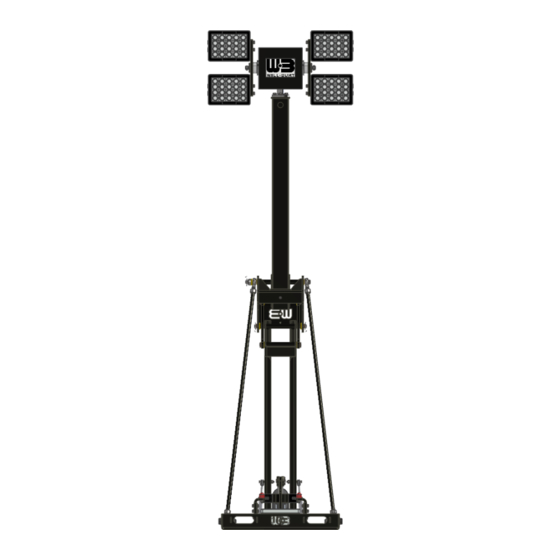
& I NSTRUCTIONS FOR IGHT NFLEXION Figure 2-1 Mast System with RCP and Four X200 Lights Original Instructions TP-5554501-B 2019... -
Page 37: Figure 2-2 Mast System With Rcp And Two X200 Lights
& I NSTRUCTIONS FOR IGHT NFLEXION Figure 2-2 Mast System with RCP and Two X200 Lights TP-5554501-B Original Instructions May 2019... -
Page 38: Figure 2-3 Mast System With Rcp And No Lights
& I NSTRUCTIONS FOR IGHT NFLEXION Figure 2-3 Mast System with RCP and no Lights Original Instructions TP-5554501-B 2019... -
Page 39: Figure 2-4 Mast System With No Rcp And No Lights (Inflexion Hd)
& I NSTRUCTIONS FOR IGHT NFLEXION Figure 2-4 Mast System with no RCP and no Lights (Inflexion HD) TP-5554501-B Original Instructions May 2019... -
Page 40: Power Supply Requirements
& I NSTRUCTIONS FOR IGHT NFLEXION 2.5 Power Supply Requirements The mast control system: Requires a 20-30 VDC power supply for the mast control system Requires 10 AWG Wire (6 mm ) or heavier power cable with maximum length of 15 meters (50 ft.), 10/2 SJOW cable or equivalent ... -
Page 41: System Installation
These instructions assume that the mounting hole locations are not pre-drilled and that the Night Scan Lite or Inflexion HD components will be used as templates to drill these holes during installation. Alternatively, the mounting hole location could be found and pre-drilled using the installation dimensions (Section 2.4). -
Page 42: Select A Suitable Mounting Location
Junction Box to HHRC o Customer Power to Control Box 2.6.1.2 Unpack the Night Scan Lite/Inflexion HD During installation, it will be necessary to lift the mast. The process described in this manual represents a possible method of lifting the mast. Depending on the environment and equipment available, other methods may work better. -
Page 43: Figure 2-5 Permissible Sling Points
& I NSTRUCTIONS FOR IGHT NFLEXION Unpack the system as follows: 1. Carefully open the shipping crate. 2. Inspect for any shipping damage. Notify the carrier if damage is evident. 3. Remove all loose components. 4. Outfit the mast with a sling and hoist capable of supporting the mast weight. The sling must support the mast from as least three points. -
Page 44: Secure The Mast Assembly
& I NSTRUCTIONS FOR IGHT NFLEXION 2.6.1.3 Secure the Mast Assembly To secure the Mast Assembly: 1. Carefully move the Mast Assembly into position in the mounting location. 2. Use the Base of the Mast Assembly as a template to drill eight mounting holes (Figure 2-6) into the mounting structure. -
Page 45: Secure The Junction Box
The recommended installation torque for M6 Stainless Steel bolts is 7-8 Nm (5-6 ft-lb.). Note: An Operation Label (P/N: 5555101) ships loose with the Mast System for Night Scan Lite. This label includes important warning symbols also located on the Mast Assembly. This label shall be applied in a location visible to the operator while operating the mast system. -
Page 46: Electrical Installation Detailed Instructions
NFLEXION 2.6.2 Electrical Installation Detailed Instructions The following are detailed steps describing the electrical installation of the Night Scan Lite and Inflexion HD. The exact installation procedures may vary based on the configuration of the system being used and the installation environment. Use the best and safest method for your circumstances. -
Page 47: Figure 2-9 Night Scan Lite Power Relay Wiring Diagram
& I NSTRUCTIONS FOR IGHT NFLEXION Figure 2-9 Night Scan Lite Power Relay Wiring Diagram TP-5554501-B Original Instructions 2-15 May 2019... -
Page 48: Figure 2-10 Night Scan Lite Main Control Board Wiring Diagram
& I NSTRUCTIONS FOR IGHT NFLEXION Figure 2-10 Night Scan Lite Main Control Board Wiring Diagram 2-16 Original Instructions TP-5554501-B 2019... -
Page 49: Figure 2-11 Night Scan Lite Remote Junction Box Wiring Diagram
& I NSTRUCTIONS FOR IGHT NFLEXION Figure 2-11 Night Scan Lite Remote Junction Box Wiring Diagram TP-5554501-B Original Instructions 2-17 May 2019... -
Page 50: Partially Extend The Mast Manually
& I NSTRUCTIONS FOR IGHT NFLEXION The Control Box Assembly: Is located underneath the RCP when the mast is fully nested. Has eight locations with cable grips for cables used as described in Figure 2-12. Control Box Control Box Assembly Contains Assembly... -
Page 51: Wire Junction Box To Main Control Board
& I NSTRUCTIONS FOR IGHT NFLEXION 4. Once the screw is removed, insert the drive flexible extension with a 6mm hex bit long enough to engage the manual override shaft in the back of the actuator. Crank counterclockwise with a manual ratchet wrench to extend the mast. Once the mast is raised enough to insert a standard hex wrench, a standard hex wrench can be used. -
Page 52: Wire Vehicle Interlock On Sensor
9. Tighten the cable grip ensuring there is adequate slack inside the control box. 2.6.2.3 Wire Vehicle Interlock on Sensor The Night Scan Lite and Inflexion HD is designed to allow for integration into vehicle safety circuitry to eliminate the possibility of driving with the mast extended. Usage shall be used to comply with various safety standards such as NFPA-1901. -
Page 53: Figure 2-15 Proximity Sensor
& I NSTRUCTIONS FOR IGHT NFLEXION position, adjust the sensor 1 mm closer to the moving base section and tighten the nut to 67-80 N·m. Ensure the lock washer is seated on both sides. The end of the sensor should be approximately 5 mm away from the moving base section after adjustment. -
Page 54: Wire Optional Auxiliary Devices To Power Relay Board
& I NSTRUCTIONS FOR IGHT NFLEXION Figure 2-16 Vehicle Interlock Circuit Wiring Diagram 2.6.2.4 Wire Optional Auxiliary Devices to Power Relay Board Depending on the configuration of your system, there may be additional auxiliary devices installed such as a strobe or beacon light, or a camera. The Power Relay Board allows for up to two auxiliary devices to be installed with a maximum amp draw of 10 amps per device. -
Page 55: Wire Power For Optional Auxiliary Devices To Power Relay Board
& I NSTRUCTIONS FOR IGHT NFLEXION 1. Run a 14 AWG (2.5 mm ) wire from the auxiliary device to the Control Box Assembly. 2. Locate terminal block TB6 on the Power Relay Board (P/N: 5553301). 3. Secure the wire to TB6 at either AUX 1 or AUX 2 as shown in Figure 2-17. Figure 2-17 Power Relay Board Terminal Block TB6 2.6.2.5 Wire Power for Optional Auxiliary Devices to Power Relay Board If an auxiliary device is installed on the system, customer fused or breaker protected power will... -
Page 56: Wire Power For Lights Or Payload To Power Relay Board
& I NSTRUCTIONS FOR IGHT NFLEXION 2.6.2.6 Wire Power for Lights or Payload to Power Relay Board The X200 LED lights can use a 20-30 VDC power supply. The customer should supply fused or breaker-protected power for the lights or alternate payload. Each light bank or payload can have up to a 20 amp draw per side or 40 amps total. -
Page 57: Figure 2-20 Payload Cable Routing
& I NSTRUCTIONS FOR IGHT NFLEXION Follow the routing instructions in Figure 2-20 for the RCP cable to install cabling for Inflexion HD payloads. Figure 2-20 Payload Cable Routing OPTIONAL 12 VDC SUPPLY: The following information defines how to power the Mast System with a 10-15 VDC power supply (battery). -
Page 58: Wire Power For Mast And Control To Power Relay Board
& I NSTRUCTIONS FOR IGHT NFLEXION Figure 2-21 12VDC Input Power Wiring 2.6.2.7 Wire Power for Mast and Control to Power Relay Board The mast and control require a 20-30 VDC power supply with a nominal power of 24 VDC. The system may have an amp draw of up to 20 amps. -
Page 59: Finalize Electrical Installation
& I NSTRUCTIONS FOR IGHT NFLEXION 4. Tighten the cable grip ensuring proper slack inside the control box. See Section 2.6.2.6 for optional powering with 10-15 VDC power supply. 2.6.2.8 Finalize Electrical Installation To finalize the electrical installation: 1. Ensure all wiring is complete. 2. -
Page 60: Test The Installation
NSTRUCTIONS FOR IGHT NFLEXION 2.7 Test the Installation Follow all precautions while testing the Night Scan Lite or Inflexion HD installation. To test the installation: 1. Review the Pre-Operation Check (Section 3.1). 2. Initiate the System (Section 3.4.2.1). 3. Extend the mast (Section 3.4.2.2). -
Page 61: Figure 2-25 Inflexion Hd Payload Saddle
) minimum) needs to be added as noted above to allow the mast to retract. The Night Scan Lite with RCP will arrive with the payload saddles factory adjusted. For the Inflexion HD with other payloads, the installer shall ensure the payload is secure from shock and vibration damage in the nested position during vehicle transport. - Page 62 & I NSTRUCTIONS FOR IGHT NFLEXION 2-30 Original Instructions TP-5554501-B 2019...
-
Page 63: Section 3 Operation
& I NSTRUCTIONS FOR IGHT NFLEXION Section 3 Operation This section describes operation of the system. The exact operating procedures will vary based on the configuration of your system. Follow the appropriate operation procedures for your system. Use care to understand and follow all precautions while operating. 3.1 Pre-Operation Check Before operating the system, ensure: ... -
Page 64: Operation Equipment
& I NSTRUCTIONS FOR IGHT NFLEXION Safety Instruction – Operation! Mast is recommended for outdoor operation. If used indoors, ensure overhead area is free of power lines or other overhead obstructions. Do not use in areas that have been classified as hazardous as defined in Article 500 of the National Electric Code (United States). -
Page 65: Controls
& I NSTRUCTIONS FOR IGHT NFLEXION 3.3 Controls The following controls are available on your system: Symbol Name Function Provides an emergency stop of the system when pressed. All mast and RCP motion will stop and the system powers down. Emergency Stop Switch Emergency Stop Switch must be twisted and pulled to enable... -
Page 66: Operation
& I NSTRUCTIONS FOR IGHT NFLEXION 3.4 Operation This section describes operation of the Mast System using powered operation. If an emergency stop is required at any time, press the Emergency Stop Switch on the Junction Box. All mast and RCP motion will stop. If an emergency stop event occurs, after actuation and before disengaging the emergency stop, the mast system shall be inspected in order to detect the reason for the actuation. -
Page 67: Extend The Mast
& I NSTRUCTIONS FOR IGHT NFLEXION 4. Press the Start button, on the Junction Box, to initiate system power. The power LED (Figure 3-1) on the HHRC will turn green when the system is powered. Power Figure 3-1 Power LED Note: If the system is powered and stays nested with no other commands, the system will power off after 60 seconds of inactivity. -
Page 68: Operate The Rcp And Lights
& I NSTRUCTIONS FOR IGHT NFLEXION 3.4.2.3 Operate the RCP and Lights All RCP, AUX and Light functions are prohibited by the control until the mast has reached the fully extended height. Attempts to pan and tilt the RCP while at an intermediate height are prohibited by the control to protect the lights or payload from crashing into the vehicle while deploying or retracting. -
Page 69: Retract The Mast
& I NSTRUCTIONS FOR IGHT NFLEXION 3.4.2.5 Retract the Mast To retract the mast: 1. Press and hold the Mast Down button until the mast reaches the fully nested position and all mast motion stops. When the Mast Down button is pressed and held, the RCP will automatically home itself, if it is not already in the home position, before allowing the mast to lower. -
Page 70: Manual Operation Of The Mast
& I NSTRUCTIONS FOR IGHT NFLEXION 3.4.3 Manual Operation of the Mast Safety Instruction – Pinching/Crushing Hazard! Never manually operate the mast while power is still applied to the system. Ensure the Mast System is de-energized and the power isolation procedure is followed. Any attempt to electrically energize the Mast System when manually operating the mast may result in injury. -
Page 71: Section 4 Transportation
& I NSTRUCTIONS FOR IGHT NFLEXION Section 4 Transportation Before transporting the system, the system needs to be secured. The exact procedures for transportation will vary based on the system configuration. The process described in this manual represents a possible method of transporting the mast. Depending on the environment and equipment available, other methods may work better. -
Page 72: Shipping
& I NSTRUCTIONS FOR IGHT NFLEXION 4.2 Shipping When shipping the system, The Will-Burt Company recommends shipping the mast in the original shipping crate (P/N: 5567801). If the original shipping crate is not available, contact The Will-Burt Company to order a replacement. Safety Instruction –... -
Page 73: Section 5 Maintenance
& I NSTRUCTIONS FOR IGHT NFLEXION Section 5 Maintenance This section describes maintenance procedures required to keep the system operational Use care to understand and follow all precautions while performing these procedures. 5.1 Pre-Maintenance Check Before performing maintenance procedures, ensure the following precautions are understood and followed: Trained Personnel Only! Only trained and qualified personnel should perform maintenance and servicing procedures. -
Page 74: Power Isolating Procedure
& I NSTRUCTIONS FOR IGHT NFLEXION 5.2 Power Isolating Procedure All power sources shall be removed from the mast system including mast controls, lighting power, auxiliary device power before performing any maintenance operation on the mast system. To isolate power to the mast system: 1. -
Page 75: Spare Parts
& I NSTRUCTIONS FOR IGHT NFLEXION 5.4 Spare Parts To order spare or replacement parts, always refer to the mast model number and serial number. The model number, serial number, and additional information is engraved on the mast Identification Plate. Throughout this manual, “P/N” followed by a number represent the part number for that component. - Page 76 & I NSTRUCTIONS FOR IGHT NFLEXION Frequency Inspection Action Fasteners – Inspect external Monthly Replace any missing or damage fasteners, shaft safety pins, snap hardware. If any hardware is found rings, and actuator coupling pin loose, retighten. If loose fasteners retaining clip.
- Page 77 & I NSTRUCTIONS FOR IGHT NFLEXION Frequency Inspection Action Side Saddle Adjustment – Attempt Monthly If side-to-side play is observed to move the top tube or RCP side-to- greater than 1/16 inches (1.5 mm), side in the saddle in the mast nested adjust the saddle plates to reduce position.
-
Page 78: Cleaning The System
& I NSTRUCTIONS FOR IGHT NFLEXION 5.6 Cleaning the System Health and Safety Hazard! Solvent used to clean parts is potentially dangerous. Follow solvent manufacturer’s safety procedures and recommendations. Avoid inhalation of fumes and also prolonged contact to skin. Death or serious injury could occur if solvents are not handled properly. -
Page 79: Section 6 Troubleshooting
& I NSTRUCTIONS FOR IGHT NFLEXION Section 6 Troubleshooting This section describes troubleshooting for the Mast System. Use care to understand and follow all precautions while troubleshooting the Mast System. TP-5554501-B Original Instructions May 2019... -
Page 80: Adjust Rcp Saddles
& I NSTRUCTIONS FOR IGHT NFLEXION 6.1 Adjust RCP Saddles The saddles are adjusted in the factory for new masts. Over time, vibration during transportation and wear may cause the RCP and payload to bounce excessively. If excessive bouncing is observed, the RCP saddles (Figure 6-1) may be adjusted upwards to cause the RCP to sit tighter on the saddle in the nested position. -
Page 81: Adjust Side Saddles
& I NSTRUCTIONS FOR IGHT NFLEXION To adjustment the RCP saddle heights: 1. Ensure the mast is in the nested position with the RCP resting on the saddles. 2. Ensure power is removed from the system according to the Power Isolating Procedure (Section 5.2.) 3. - Page 82 & I NSTRUCTIONS FOR IGHT NFLEXION Original Instructions TP-5554501-B 2019...
-
Page 83: Section 7 Reference
& I NSTRUCTIONS FOR IGHT NFLEXION Section 7 Reference This section provides reference information for the system as follows: Extended Glossary of Terms (Section 7.1) Disposal of Mast System (Section 7.2) 7.1 Extended Glossary of Terms This section describes general terms and abbreviations used within this manual. ... -
Page 84: Disposal Of Mast System
IGHT NFLEXION “Mast System” to refer to the entire Night Scan Lite Mast System (Mast Assembly, Junction Box, Hand-Held Remote Control, and Junction Box Cable). “Nested” refers to the position of the mast were the mast sections have not extended (Figure 7-2).
Need help?
Do you have a question about the NIGHT SCAN LITE and is the answer not in the manual?
Questions and answers