Table of Contents
Advertisement
The Will-Burt Company
401 Collins Blvd
Orrville, OH 44667, USA
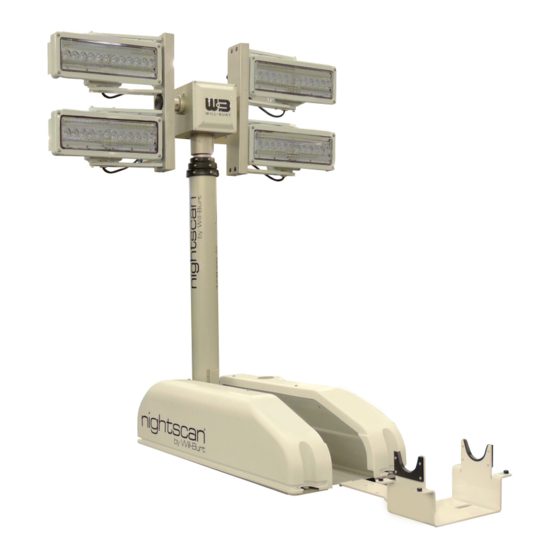
Night Scan Chief
Operating Instructions
Phone: +1 330 682 7015
E-Mail: contact_us@willburt.com
Website: www.willburt.com
Authorized Representative:
GEROH GmbH & Co. KG
Fischergasse 25
D-91344 Waischenfeld, Germany
TP-4602001-T, December 2020
© 2020 The Will-Burt Company
Original Instructions
Advertisement
Table of Contents
Troubleshooting

Related Manuals for Will Burt Night Scan Chief Series


Summary of Contents for Will Burt Night Scan Chief Series
- Page 1 Night Scan Chief Operating Instructions The Will-Burt Company Phone: +1 330 682 7015 TP-4602001-T, December 2020 401 Collins Blvd E-Mail: contact_us@willburt.com © 2020 The Will-Burt Company Orrville, OH 44667, USA Website: www.willburt.com Original Instructions Authorized Representative: GEROH GmbH & Co. KG Fischergasse 25 D-91344 Waischenfeld, Germany...
- Page 3 NIGHT SCAN CHIEF OPERATING INSTRUCTIONS Warranty Will-Burt warrants its Night Scan Chief to be free from defects in material and workmanship for a period of two (2) years, with such time period running from the date of shipment by Will-Burt. Will- Burt shall not be responsible for any damage resulting to or caused by its products by reason of failure to properly install, maintain or store the product;...
-
Page 4: Table Of Contents
NIGHT SCAN CHIEF OPERATING INSTRUCTIONS Contents 1 Safety Summary....................5 1.1 Signal Word Definitions..................... 5 1.2 Safety Instructions ....................5 1.3 Symbols Used on Product Labels................10 2 Specification Compliance ................. 11 2.1 NFPA 1901-2016 ....................11 2.2 CE Declaration of Conformity ................. 11 3 Introduction ...................... - Page 5 NIGHT SCAN CHIEF OPERATING INSTRUCTIONS 7 Maintenance, Adjustments and Disposal ............41 7.1 Power Isolating Procedure ..................41 7.2 Cleaning and Lubricating the System ..............41 7.3 Spare Parts ......................42 7.4 Periodic Inspections....................42 7.5 Adjusting the 90° and Mast Stowed Limit Switches ..........44 7.5.1 Diagnostic LEDs on the Base PC Board............
- Page 6 NIGHT SCAN CHIEF OPERATING INSTRUCTIONS PAGE 4 OF 80 TP-4602001-T DECEMBER 2020...
-
Page 7: Safety Summary
NIGHT SCAN CHIEF OPERATING INSTRUCTIONS Safety Summary This section describes safety instructions for the Night Scan Chief that personnel must under- stand and apply throughout all product activities such as transportation, handling, installation, operation, maintenance, storage, disposal and troubleshooting. Read and understand this entire document, and contact The Will-Burt Company with any questions, before performing any proce- dure outlined in this document. - Page 8 NIGHT SCAN CHIEF OPERATING INSTRUCTIONS weight, payload sail area, wind speed, guy line arrangement, support bracket or roof line loca- tion, and base plate assembly. Do not operate in wind speed conditions exceeding the maximum rated wind speed. Do not operate on slopes exceeding the maximum deployment angle. Do not install a payload that exceeds the maximum payload lifting capacity of mast.
- Page 9 NIGHT SCAN CHIEF OPERATING INSTRUCTIONS Erratic Mast Operation Impact Hazard! The mast should operate smoothly during extension and retraction. If erratic mast motion is observed during extension or retraction that results in impact loading between the tube and the tube collar (mechanical travel stop), cease use of the mast and contact The Will-Burt Company service department.
- Page 10 NIGHT SCAN CHIEF OPERATING INSTRUCTIONS solvent away from ignition sources. Always store cleaning solvent in the proper marked container and in a proper location. Bright Light Radiation Hazard! For systems equipped with scene lighting or look-up lights, do not look directly into lights when they are illuminated. Temporary impairment or permanent vision damage could occur.
- Page 11 NIGHT SCAN CHIEF OPERATING INSTRUCTIONS Fastener Vibration Hazard! Mast system and payload mounting hardware must include proper means to resist vibration loosening such as thread-locking compound, locking hardware, or equivalent. Use specified assembly torques appropriate for the fastener size. Frozen Water Hazard! Water freezing inside mast may render mast inoperable and cause major equipment damage such as tube deformation.
-
Page 12: Symbols Used On Product Labels
NIGHT SCAN CHIEF OPERATING INSTRUCTIONS Safety Instruction - Motion on Power Interruption or Emergency Stop! Mast uses a normally open air control valve. If power is lost or turned off or the emergency stop is activated while mast is extended, mast will begin releasing air pressure and retracting at a controlled rate until power is restored or mast fully retracts. -
Page 13: Specification Compliance
NIGHT SCAN CHIEF OPERATING INSTRUCTIONS Specification Compliance NFPA 1901-2016 The mast system is designed to be compliant with the following sections of National Fire Protec- tion Agency NPFA-1901-2016 Edition: 22.14 Powered Operated Light Masts 23.13 Power Operated Masts CE Declaration of Conformity A copy of the EU Declaration of Conformity is as follows: TP-4602001-T PAGE 11 OF 80... - Page 14 NIGHT SCAN CHIEF OPERATING INSTRUCTIONS EU Declaration of Conformity The Will-Burt Company 401 Collins Blvd Orrville, OH 44667, USA hereby declares that the following product Product designation: Telescoping Mast and Light Tower Model Name: Night Scan Chief Type name: Mobile lighting tower and mast Serial number: All Trade name: Night Scan Chief Year of construction: 2021...
-
Page 15: Introduction
NIGHT SCAN CHIEF OPERATING INSTRUCTIONS Introduction Introduction Thank you for selecting The Will-Burt Company for your critical payload elevation needs. These operating instructions describe transporting, handling, installing, operating, maintaining, storing, and troubleshooting procedures for Night Scan Chief. These procedures assume the use of stan- dard mast systems. -
Page 16: Mast Position Definition
NIGHT SCAN CHIEF OPERATING INSTRUCTIONS Mast Position Definition An actuator electrically tilts the mast from the stowed position to the 90° position. The mast is then pneumatically moved by air pressure to the extended position. The following positions (see Figure 3-1) are used throughout this manual: •... - Page 17 NIGHT SCAN CHIEF OPERATING INSTRUCTIONS Magnetic Down Switch: The magnetic down switch is activated by a magnet in the mast top tube section. The position is factory set to indicate when the mast is fully retracted. Once acti- vated, the mast is free to tilt back to the stowed position. See Section 7.5.4 for optional adjust- ment.
- Page 18 NIGHT SCAN CHIEF OPERATING INSTRUCTIONS Saddle Wiring Access Holes Base Board Electrical Ground Bar Look-Up Light Figure 3-3 Night Scan Chief Components (Left Cover Removed) 90° Limit Switch Stowed Limit Switch Tilt Actuator Safety Valve Air Compressor (or Valve) Figure 3-4 Night Scan Chief Components (Right Cover Removed) 90°...
-
Page 19: Remote Control Options
NIGHT SCAN CHIEF OPERATING INSTRUCTIONS vehicle surface is not flat, this switch may need to be adjusted for proper stowing of the mast. See Section 7.5.3 for optional adjustment procedure. Tilt Actuator: This actuator tilts the mast. Safety Valve: This valve prevents over-pressurization of the mast system. Air Compressor: The air compressor provides the air pressure required to raise the mast. - Page 20 NIGHT SCAN CHIEF OPERATING INSTRUCTIONS HHRC PMRC WHHRC Figure 3-5 Remote Control Options (not to scale) The HHRC plugs into a bulkhead connector that can be located remotely on the vehicle at the operator’s station. See Figure 3-6. Figure 3-6 HHRC Bulkhead Connection PAGE 18 OF 80 TP-4602001-T DECEMBER 2020...
-
Page 21: Technical Data
NIGHT SCAN CHIEF OPERATING INSTRUCTIONS Technical Data Table 4-1 Night Scan Chief Technical Data Night Scan Chief Extended Height (ft / m) 3.25 / 1.0 6 / 1.8 7.5 / 2.3 System Weight Range (lb / kg) 97-135 / 44-61 Mast Control System Input Voltage 12VDC - 24VDC Mast Control System Current... - Page 22 NIGHT SCAN CHIEF OPERATING INSTRUCTIONS PAGE 20 OF 80 TP-4602001-T DECEMBER 2020...
-
Page 23: Installation
NIGHT SCAN CHIEF OPERATING INSTRUCTIONS Installation This section describes the physical and electrical installation of the Night Scan Chief and pro- vides the general procedures that must be followed to ensure a successful installation. Be sure to read and understand the entire installation procedure and the Safety Summary Section 1 before beginning installation. -
Page 24: Recommended Installation Tools
NIGHT SCAN CHIEF OPERATING INSTRUCTIONS Saddle: 35 lb (16 kg) 200 lb (91 kg) 575 lb (261 kg) (single point load in center) (load at each mounting hole) (load at each mounting hole) Figure 5-1 Night Scan Chief Reaction Loads on Mounting Structure Recommended Installation Tools Table 5-1 lists recommended tools and materials for installation. -
Page 25: Attaching To Mounting Location
NIGHT SCAN CHIEF OPERATING INSTRUCTIONS 5. Unbolt (for wooden crates) and remove any banding fixing the mast to the shipping crate or carton. Remove any banding fixing the mast. 6. Using a hoist, lift the Night Scan Chief from the shipping container by the mast tube at the labeled center of gravity symbol (Figure 5-2) position. -
Page 26: Installing Remote Control
NIGHT SCAN CHIEF OPERATING INSTRUCTIONS Figure 5-3 Night Scan Chief Installation Dimensions (Bottom View) Inches [mm] Table 5-2 Installation Dimensions Model Dimension A Value (from Figure 5-3) Night Scan Chief 1.0 44.283 inches [1124.8 mm] Night Scan Chief 1.8 40.130 inches [1019.3 mm] Night Scan Chief 2.3 46.190 inches [1173.2 mm] Installing Remote Control... - Page 27 NIGHT SCAN CHIEF OPERATING INSTRUCTIONS 1. Drill clearance holes for 1/4-20 screws located per Figure 5-4. Either two hole pattern can be selected according to the space available. 2. Using the screws, washers, and nuts provided, attach the bulkhead to the vehicle. Torque the 1/4-20 screws to 62-70 inch-pounds (7-8 Newton-Meters).
-
Page 28: Panel Mount Remote Control (Pmrc)
NIGHT SCAN CHIEF OPERATING INSTRUCTIONS installation. Use the proper installation torque for the screw selected and use thread locking techniques to prevent the screws from backing out due to vibration. Mount the holder ensur- ing the wedged side in the groove is facing upward to mate to the HHRC. 3. -
Page 29: Wireless Remote Control
NIGHT SCAN CHIEF OPERATING INSTRUCTIONS Figure 5-6 PMRC Panel Cutout Dimensions A loose wiring connector is shipped with the PMRC to allow cable routing in the vehicle. Once the cable is routed, wire the connector and attach the connector to the back of the PMRC. To wire the PMRC connector: 1. -
Page 30: Wiring Remote Control Cable To The Base Board
NIGHT SCAN CHIEF OPERATING INSTRUCTIONS ments shown on the wiring diagram. To electrically connect the Night Scan Chief, proceed as fol- lows: 1. Remove the three screws from the left cover of the base (as viewed from the back of the unit) and remove the cover. - Page 31 NIGHT SCAN CHIEF OPERATING INSTRUCTIONS It is important to calculate the current draw for the wires in each lighting circuit. To calculate the current draw for the wires: • Divide the total watts of the entire mast unit by two (since there are two circuits). •...
-
Page 32: Wiring Vehicle Safety Interconnect Circuit
NIGHT SCAN CHIEF OPERATING INSTRUCTIONS For Condition #2 (12 VDC with >20 Amps per circuit) a solenoid valve is added to the system to manage the higher current load. This solenoid valve assembly includes a separate terminal block to land the 12 VDC light power. Connect the left and right light power to the terminal block as shown in Figure 5-7 following the polarity listed on the terminal block label. -
Page 33: Wiring Optional Enable Circuit
NIGHT SCAN CHIEF OPERATING INSTRUCTIONS Figure 5-8 Example Vehicle Safety Interconnect Circuit The contact output is set at the factory to be OPEN when the mast is active (not stowed) by set- ting the S2-1 dip switch to the OFF (OPEN) position. To change the contact output to be CLOSED when the mast is active, set the S2-1 dip switch to the ON (CLOSED) position. -
Page 34: Test The Installation
NIGHT SCAN CHIEF OPERATING INSTRUCTIONS Test the Installation Review the Operation Section 6 and Safety Summary Section 1 and observe all safety dangers, warnings, and cautions before proceeding to test the installation. If any part of the testing fails, check the LEDs on the controller and Base Board. To test the installation, proceed as follows: 1. -
Page 35: Operation
NIGHT SCAN CHIEF OPERATING INSTRUCTIONS Operation This section describes the operation of the system. Be sure to read and understand the entire operation procedure and the Safety Summary Section 1 before beginning operation. Pre-Operation Check Before operating the system: 1. Ensure that there are no overhead obstructions, and that there are no power lines within 20 feet (6 meters) of the mast. -
Page 36: Initiating (Power-Up)
NIGHT SCAN CHIEF OPERATING INSTRUCTIONS 4. Raise the mast to 90° and turn on the lights by performing one of the following steps: 5. Quickly press "Mast Up" twice (Auto-Up feature) to move mast to 90° and turn both banks of lights on. -
Page 37: Using The Auto-Up Feature
NIGHT SCAN CHIEF OPERATING INSTRUCTIONS There are two ways to raise the mast to 90°. • Use the Auto-Up feature. • Press and hold the "Mast Up" button. There are several advantages in using the Auto-Up feature to raise the mast to 90°: •... -
Page 38: Using The Mast Up Button
NIGHT SCAN CHIEF OPERATING INSTRUCTIONS 6.5.2 Using the Mast Up Button Raise the mast to 90° using the "Mast Up" button as follows: 1. Press and hold "Mast Up" until the mast is at 90°. Press the button until the software stops the mast to ensure 90°... -
Page 39: Using The Auto Stow® Feature
NIGHT SCAN CHIEF OPERATING INSTRUCTIONS when the Mast Stowed Switch is closed, and the brief over current condition is met when the mast is driven into the saddle. Driving into the saddle ensures the RCP and lights do not “bounce” when in transit. The mast can be stowed by using: •... -
Page 40: Emergency Stow With Power
NIGHT SCAN CHIEF OPERATING INSTRUCTIONS 2. Visually inspect that the mast is properly stowed and powered down. Ensure that the payload will not bounce as the vehicle drives down the road. Once stowed, the Mast Stowed Safety Interlock Contact signals it is safe to move the vehicle. 3. -
Page 41: Emergency Stow Without Power
NIGHT SCAN CHIEF OPERATING INSTRUCTIONS 6. While observing the RCP, lights, and mast, press and hold S4 on the Base Board. 7. Ensure that the RCP and lights are properly positioned as the mast goes from 90° to the stowed position. 8. - Page 42 NIGHT SCAN CHIEF OPERATING INSTRUCTIONS 6mm Hex Head Bolt Figure 6-1 Actuator Override for Manual Retraction PAGE 40 OF 80 TP-4602001-T DECEMBER 2020...
-
Page 43: Maintenance, Adjustments And Disposal
NIGHT SCAN CHIEF OPERATING INSTRUCTIONS Maintenance, Adjustments and Disposal This section describes the routine maintenance and adjustment procedures required to keep your system operational. Be sure to read and understand the entire operation procedure and the Safety Summary Section 1 before beginning any maintenance or adjustment procedure. Power Isolating Procedure Remove all power sources from the mast system including mast controls, lighting power, auxiliary device power before performing any maintenance operation on the mast system other than... -
Page 44: Spare Parts
NIGHT SCAN CHIEF OPERATING INSTRUCTIONS 3. After light fixtures cool, clean the light lenses using a soft cloth and standard glass cleaner. After cleaning the mast, if the mast is in extremely harsh environmental conditions, lubricate the mast with TMD Mast Lubricant (P/N: 900600). TMD Mast Lubricant is specifically formulated for cold weather use, but is also suitable for year around use. - Page 45 NIGHT SCAN CHIEF OPERATING INSTRUCTIONS The Will-Burt Company. Table 7-1 provides a schedule of periodic inspections and procedures required to keep the Mast System in safe operating condition. Table 7-1 Periodic Inspections Frequency Inspection Action As Needed; In Inspect to ensure the Mast System is Clean the mast per the procedure salt water or kept clean and free from foreign...
-
Page 46: Adjusting The 90° And Mast Stowed Limit Switches
NIGHT SCAN CHIEF OPERATING INSTRUCTIONS Table 7-1 Periodic Inspections (Continued) Frequency Inspection Action Every 6 Months Extend the mast to the 90° position If the mast shows mechanical play, and make sure the mast is rigidly adjust the mast 90° limit switch driven into the rubber pad below the according to Section 7.5.2. -
Page 47: Adjusting The Mast 90° Limit Switch
NIGHT SCAN CHIEF OPERATING INSTRUCTIONS Figure 7-1 Diagnostic LEDs (stowed position example) 7.5.2 Adjusting the mast 90° Limit Switch The 90° Switch (Figure 7-2) senses when the mast is at 90° by checking the position of the actu- ator. There is a magnet mounted to the actuator arm that triggers the limit switch. When the mast is being raised from the stowed position and the 90°... -
Page 48: Adjusting The Mast Stowed Limit Switch
NIGHT SCAN CHIEF OPERATING INSTRUCTIONS 9. Replace the base covers. Mast Stowed Switch Mast 90° Switch Figure 7-2 Mast Stowed and Mast 90° Limit Switch Locations (Cover Removed) 7.5.3 Adjusting the Mast Stowed Limit Switch The Mast Stowed (near 0°) Switch (Figure 7-2) senses that the mast is in the saddle upon power up, and when the mast is nearing the saddle during stowing. -
Page 49: Adjusting The Mast Magnetic Down Switch
NIGHT SCAN CHIEF OPERATING INSTRUCTIONS 5. Lower the mast to the stowed position by holding the "Mast Down" button until the mast is stowed. Immediately release the "Mast Down" button when the mast is stowed. If you drive the mast too far into the saddle, you may receive a "1,04" error (excessive amp draw during actuator decline). -
Page 50: Adjusting The Rcp Home Position
NIGHT SCAN CHIEF OPERATING INSTRUCTIONS 6. If repeated adjustments do not succeed, use a small piece of steel or iron filings to locate the magnet in the tube and move the Banded Magnetic Switch to the magnet's location. 7. If the mast still will not stow, hold a separate magnet up to the Banded Magnetic Switch. Press the "Mast Down"... - Page 51 NIGHT SCAN CHIEF OPERATING INSTRUCTIONS Tilt Flag Tilt Flag Set Screws Pan Flag Screws Pan Flag Figure 7-3 RCP Flags (RCP cover removed) 4. Once the set screws are loose, pan and tilt the unit to the correct home position. Be careful that the flags do not come into contact when panning and tilting, or they may be bent.
-
Page 52: System Disposal
NIGHT SCAN CHIEF OPERATING INSTRUCTIONS 8. Stow the mast, watching for the RCP and lights to become oriented as described in the begin- ning of this section. If it does not look like the RCP is properly positioned during stowing, use the Emergency Stop to stop motion and re-adjust the flags. -
Page 53: Reference Information
NIGHT SCAN CHIEF OPERATING INSTRUCTIONS Reference Information This section describes reference information for your system including some optional equipment. DIP Switch Definitions DIP Switches on the Base Board and the RCP PC board are set at the factory and normally do not have to be changed. -
Page 54: Nycoil® (Optional)
NIGHT SCAN CHIEF OPERATING INSTRUCTIONS Nycoil® (Optional) The Nycoil® Cable Conduit (Figure 5 2) is an optional external coiled hose used to house electri- cal wiring, camera and positioner cables. Figure 8-2 Nycoil® Conduit Nycoil® conduit comes in a variety of sizes. Depending on the system being used, some restric- tions on the size of the Nycoil®... - Page 55 NIGHT SCAN CHIEF OPERATING INSTRUCTIONS TP-4602001-T PAGE 53 OF 80 DECEMBER 2020...
- Page 56 NIGHT SCAN CHIEF OPERATING INSTRUCTIONS PAGE 54 OF 80 TP-4602001-T DECEMBER 2020...
- Page 57 NIGHT SCAN CHIEF OPERATING INSTRUCTIONS TP-4602001-T PAGE 55 OF 80 DECEMBER 2020...
- Page 58 NIGHT SCAN CHIEF OPERATING INSTRUCTIONS PAGE 56 OF 80 TP-4602001-T DECEMBER 2020...
- Page 59 NIGHT SCAN CHIEF OPERATING INSTRUCTIONS TP-4602001-T PAGE 57 OF 80 DECEMBER 2020...
- Page 60 NIGHT SCAN CHIEF OPERATING INSTRUCTIONS PAGE 58 OF 80 TP-4602001-T DECEMBER 2020...
-
Page 61: The Will-Burt Company Mast Oil Safety Data Sheet
NIGHT SCAN CHIEF OPERATING INSTRUCTIONS The Will-Burt Company Mast Oil Safety Data Sheet TP-4602001-T PAGE 59 OF 80 DECEMBER 2020... - Page 62 NIGHT SCAN CHIEF OPERATING INSTRUCTIONS PAGE 60 OF 80 TP-4602001-T DECEMBER 2020...
- Page 63 NIGHT SCAN CHIEF OPERATING INSTRUCTIONS TP-4602001-T PAGE 61 OF 80 DECEMBER 2020...
- Page 64 NIGHT SCAN CHIEF OPERATING INSTRUCTIONS PAGE 62 OF 80 TP-4602001-T DECEMBER 2020...
-
Page 65: Troubleshooting
NIGHT SCAN CHIEF OPERATING INSTRUCTIONS Troubleshooting This section describes system troubleshooting information. Please contact The Will-Burt Com- pany if these guides do not solve the issue. Be sure to read and understand the entire operation procedure and the Safety Summary Section 1 before beginning any maintenance or trouble- shooting procedure. - Page 66 NIGHT SCAN CHIEF OPERATING INSTRUCTIONS Table 9-1 Error and Warning Codes for Base Board (Continued) Message Meaning Root Issue Potential Cause 1,02 Mast Stowed (near 0°) - Sensor outputs are bad Defective sensor or Sensor Output Error defective board 1,03 Mast Stowed (near 0°) - Sensor outputs are O.K., Base board was...
- Page 67 NIGHT SCAN CHIEF OPERATING INSTRUCTIONS Table 9-1 Error and Warning Codes for Base Board (Continued) Message Meaning Root Issue Potential Cause 1,08 Internal firmware Internal state machine detected error logic has detected an invalid state transition. Firmware logic error 1,09 Initiate Pushbutton input Initiate input has 1.
- Page 68 NIGHT SCAN CHIEF OPERATING INSTRUCTIONS Table 9-1 Error and Warning Codes for Base Board (Continued) Message Meaning Root Issue Potential Cause 1,13 RCP STOWED mag- Sensor outputs are bad Wiring problem, defec- netic sensor - Sensor tive magnetic sensor Output Error (Upper magnetic sensor on Vertical) 1,14...
- Page 69 NIGHT SCAN CHIEF OPERATING INSTRUCTIONS Table 9-2 Error and Warning Codes for RCP Message Meaning Root Issue Potential Cause WRN,2.04 Single-tilt - Tilt Stuck Checked only when Something is preventing moving out of a limit movement of left tilt position. The software mechanism, the motor is Dual-tilt - Left Tilt Stuck indicates the state of the...
- Page 70 NIGHT SCAN CHIEF OPERATING INSTRUCTIONS Table 9-2 Error and Warning Codes for RCP (Continued) Message Meaning Root Issue Potential Cause 2,07 Communication Timeout The RCP or P-T Drive Bad board or connection board has not sent out in communications link communications recently 2,08...
- Page 71 NIGHT SCAN CHIEF OPERATING INSTRUCTIONS Table 9-3 Error and Warning Codes for HHRC Message Meaning Root Issue Potential Cause WRN 3,02 Dual HHRC simultane- Two HHRCs are sending Multiple users con- ous inputs commands simultane- trolling the mast ously. If commands are not conflicting, they will be allowed (Base Board decides).
- Page 72 NIGHT SCAN CHIEF OPERATING INSTRUCTIONS Table 9-3 Error and Warning Codes for HHRC (Continued) Message Meaning Root Issue Potential Cause 3,09 RF module Error Wireless Transmitter/ Return HHRC to factory Receiver did not prop- for repair erly initialize Table 9-4 Error and Warning Codes for Wireless HHRC Message Meaning Root Issue...
-
Page 73: Troubleshooting Mechanical Symptoms
NIGHT SCAN CHIEF OPERATING INSTRUCTIONS Troubleshooting Mechanical Symptoms This section describes mechanical troubleshooting. The following table lists some problems that may be observed, but may not generate an error or warning code on the controller. Table 9-5 Mechanical Symptoms and Troubleshooting Sequence Symptom Root Issue Troubleshooting Sequence... - Page 74 NIGHT SCAN CHIEF OPERATING INSTRUCTIONS Table 9-5 Mechanical Symptoms and Troubleshooting Sequence (Continued) Symptom Root Issue Troubleshooting Sequence Mast will not Magnetic switch band- 1) Magnetic switch may be out of adjust- begin to lower clamped to mast is not acti- ment.
-
Page 75: Document History
NIGHT SCAN CHIEF OPERATING INSTRUCTIONS Document History Table 9-6 Document History Changes Backward Document Compatible Date Change Details Revision with Previous Manual Version TP-4602001-P Mar. 2016 General update Updated Sections 2.1, 2.2, 2.9, 2.11, 3.9, TP-4602001-Q Jun. 2016 4.3 and 8 TP-4602001-R Oct. - Page 76 NIGHT SCAN CHIEF OPERATING INSTRUCTIONS PAGE 74 OF 80 TP-4602001-T DECEMBER 2020...
-
Page 77: 10 Appendix
NIGHT SCAN CHIEF OPERATING INSTRUCTIONS 10 Appendix 10.1 Model with Auxiliary Air Supply (No Compressor) The Night Scan Chief comes standard with an air compressor to deliver air to the mast, however an optional air valve in conjunction with customer supplied air source may be used instead. This section discusses the differences a Night Scan Chief with air valve will have from a standard model. -
Page 78: 10.2 System Wiring Diagram
NIGHT SCAN CHIEF OPERATING INSTRUCTIONS Supply Air Inlet Figure 10-1 Supply Air Inlet Location 10.2 System Wiring Diagram The system wiring diagrams are as follows: PAGE 76 OF 80 TP-4602001-T DECEMBER 2020... - Page 79 NIGHT SCAN CHIEF OPERATING INSTRUCTIONS FORCED STOW TP-4602001-T PAGE 77 OF 80 DECEMBER 2020...
- Page 80 NIGHT SCAN CHIEF OPERATING INSTRUCTIONS PAGE 78 OF 80 TP-4602001-T DECEMBER 2020...
- Page 81 NIGHT SCAN CHIEF OPERATING INSTRUCTIONS TP-4602001-T PAGE 79 OF 80 DECEMBER 2020...
- Page 82 NIGHT SCAN CHIEF OPERATING INSTRUCTIONS PAGE 80 OF 80 TP-4602001-T DECEMBER 2020...
Need help?
Do you have a question about the Night Scan Chief Series and is the answer not in the manual?
Questions and answers