Table of Contents
Advertisement
Quick Links
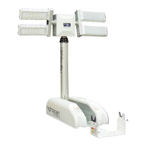
Night Scan Powerlite, Night Scan Powerlite Xtreme,
and Night Scan Powerlite Heavy Duty Towing (HDT)
Night Scan Powerlite
The Will-Burt Company
401 Collins Blvd
Orrville, OH 44667, USA
Operating Instructions
Phone: +1 330 684 4000
E-Mail: info@willburt.com
Website: www.willburt.com
Authorized Representative:
Will-Burt Germany GmbH & Co. KG
Fischergasse 25
D-91344 Waischenfeld, Germany
Night Scan Powerlite HDT
TP-4723701-U, May 2021
© 2021 The Will-Burt Company
Original Instructions
Advertisement
Table of Contents
Troubleshooting

Related Manuals for Will Burt Night Scan Powerlite


Summary of Contents for Will Burt Night Scan Powerlite
- Page 1 Night Scan Powerlite, Night Scan Powerlite Xtreme, and Night Scan Powerlite Heavy Duty Towing (HDT) Operating Instructions Night Scan Powerlite Night Scan Powerlite HDT The Will-Burt Company Phone: +1 330 684 4000 TP-4723701-U, May 2021 401 Collins Blvd E-Mail: info@willburt.com ©...
- Page 3 OPERATING INSTRUCTIONS Warranty Will-Burt warrants its Night Scan Powerlite, Night Scan Powerlite Xtreme, and Night Scan HDT to be free from defects in material and workmanship for a period of two (2) years, with such time period running from the date of shipment by Will-Burt. Will-Burt shall not be responsible for any damage resulting to or caused by its products by reason of failure to properly install, maintain or store the product;...
-
Page 4: Table Of Contents
NIGHT SCAN POWERLITE, POWERLITE XTREME, AND POWERLITE HDT OPERATING INSTRUCTIONS Contents 1 Safety Summary....................5 1.1 Signal Word Definitions..................... 5 1.2 Safety Instructions ....................5 1.3 Symbols Used on Product Labels................10 2 Specification Compliance ................. 13 2.1 NFPA 1901-2016 ....................13 2.2 CE Declaration of Conformity ................. - Page 5 NIGHT SCAN POWERLITE, POWERLITE XTREME, AND POWERLITE HDT OPERATING INSTRUCTIONS 6.9.4 Emergency Stow without Power ..............54 7 Maintenance, Adjustments and Disposal ............55 7.1 Power Isolating Procedure ..................55 7.2 Cleaning and Lubricating the System ..............55 7.3 Spare Parts ......................57 7.4 Periodic Inspections....................
- Page 6 NIGHT SCAN POWERLITE, POWERLITE XTREME, AND POWERLITE HDT OPERATING INSTRUCTIONS PAGE 4 OF 98 TP-4723701-U MAY 2021...
-
Page 7: Safety Summary
OPERATING INSTRUCTIONS Safety Summary This section describes safety instructions for the Night Scan Powerlite, Night Scan Powerlite Xtreme, and Night Scan HDT that personnel must understand and apply throughout all product activities such as transportation, handling, installation, operation, maintenance, storage, disposal and troubleshooting. - Page 8 Adhere to the safety instructions when carrying out any activity relating to the Night Scan Powerlite, Night Scan Powerlite Xtreme, and Night Scan HDT. PAGE 6 OF 98...
- Page 9 NIGHT SCAN POWERLITE, POWERLITE XTREME, AND POWERLITE HDT OPERATING INSTRUCTIONS Trained Personnel Only! This product is intended for use by trained professionals only. It is not intended for general use by the public or untrained personnel. Handling, installation, operation and maintenance to be performed by trained and authorized personnel only. Only a properly trained and qualified certified electrician should perform electric installations and service.
- Page 10 NIGHT SCAN POWERLITE, POWERLITE XTREME, AND POWERLITE HDT OPERATING INSTRUCTIONS Health and Safety Hazard while Cleaning! Solvent used to clean parts is potentially dangerous. Avoid inhalation of fumes and prolonged contact to skin. Fire Hazard Solvent! Cleaning solvent, used for maintenance, is flammable and can be explosive.
- Page 11 NIGHT SCAN POWERLITE, POWERLITE XTREME, AND POWERLITE HDT OPERATING INSTRUCTIONS Equipment Damage - Submerged! Do not submerge mast in liquid or operate the vehicle in a fording situation that would result in a submerged mast. Safety Instruction - Potential Air Contaminants! If internally mounted in a vehicle, air from mast and any accumulated water will discharge into the vehicle.
-
Page 12: Symbols Used On Product Labels
NIGHT SCAN POWERLITE, POWERLITE XTREME, AND POWERLITE HDT OPERATING INSTRUCTIONS Emergency Stow! Using the emergency stow button causes the actuator to lower mast without regard to any faults, switches, or system interlocks. It is totally up to the operator to ensure safe operation during an emergency stow attempt. - Page 13 NIGHT SCAN POWERLITE, POWERLITE XTREME, AND POWERLITE HDT OPERATING INSTRUCTIONS This symbol indicates an electrical ground connection point. This symbol is used to indicate the center of gravity (COG) of a fully nested mast in a horizontal transport position. TP-4723701-U...
- Page 14 NIGHT SCAN POWERLITE, POWERLITE XTREME, AND POWERLITE HDT OPERATING INSTRUCTIONS PAGE 12 OF 98 TP-4723701-U MAY 2021...
-
Page 15: Specification Compliance
NIGHT SCAN POWERLITE, POWERLITE XTREME, AND POWERLITE HDT OPERATING INSTRUCTIONS Specification Compliance NFPA 1901-2016 The mast systems are designed to be compliant with the following sections of National Fire Protection Agency NPFA-1901-2016 Edition: 22.14 Powered Operated Light Masts 23.13 Power Operated Masts CE Declaration of Conformity Refer to the Product page at www.willburt.com for the latest Declaration of Conformity. - Page 16 NIGHT SCAN POWERLITE, POWERLITE XTREME, AND POWERLITE HDT OPERATING INSTRUCTIONS PAGE 14 OF 98 TP-4723701-U MAY 2021...
-
Page 17: Introduction
• Night Scan Powerlite Xtreme 7.5 (7.5 m / 25 feet) • Night Scan Powerlite HDT The 2.3 model is a hybrid between the Night Scan Chief and Night Scan Powerlite. This model uses the Base design from the Chief with the Dual-Tilt RCP from the Powerlite. The RCP and operating instructions for this model follow this document. -
Page 18: Intended Use
NIGHT SCAN POWERLITE, POWERLITE XTREME, AND POWERLITE HDT OPERATING INSTRUCTIONS The Night Scan Powerlite, Night Scan Powerlite Xtreme, and the Night Scan Powerlite HDT are available with many options installed by The Will-Burt Company, including the option to come with a Profiler, which is a space-saving roof-mounted unit designed to enable installation on vehicles with limited available mounting space. -
Page 19: Mast Position Definition
NIGHT SCAN POWERLITE, POWERLITE XTREME, AND POWERLITE HDT OPERATING INSTRUCTIONS Mast Position Definition An actuator electrically tilts the mast from the stowed position to the 90° position. The mast is then pneumatically moved by air pressure to the extended position. The following positions (see Figure 3-2) are used throughout this manual: •... -
Page 20: Mast Component Descriptions
RCP: The Remote Control Positioner (RCP) pans and tilts the lights. The RCP does not become active until the mast tilts up to the 90° position. Standard Night Scan Powerlite, Night Scan Powerlite Xtreme, and Night Scan Powerlite HDT masts come equipped with a dual-tilt RCP. This means the left and right lights tilt independently to direct light at a desired position(s). - Page 21 Wiring/Air Access Panel Remote Control Positioner (RCP) Figure 3-4 Night Scan Powerlite and Night Scan Powerlite Xtreme Top View Base Board: The PC Board (PCB) contains the system logical controller and provides landing points for customer power supply and vehicle interlock cables. The PCB also distributes DC (and optional AC light) power to components in the system.
- Page 22 Saddle: The saddle supports the RCP and lights when nested for stable vehicle transit. The saddle position varies by model. Lights: The Night Scan Powerlite, Night Scan Powerlite Xtreme, and Night Scan Powerlite HDT systems can come with a variety of LED or Halogen lighting packages. Go to www.willburt.com for additional information on available light packages.
- Page 23 Wiring/Air Access Panel Base Board Electrical Ground Bar Look-Up Light Figure 3-7 Above: Night Scan Powerlite, Night Scan Powerlite Xtreme, and Night Scan Powerlite HDT Components (Left Cover Removed); Below: Night Scan Powerlite with Profiler Parts Stowed Limit Switch 90° Limit Switch...
- Page 24 Power Converter: The Power Converter is standard with the Night Scan Powerlite HDT, but it is optional with other Night Scan Powerlite models. The system uses a 12 to 48 volt DC to DC power converter (Figure 5-13). The power converter has a 58 volt, 30 amp fuse (P/N: 221033) on the output side.
-
Page 25: Remote Control Options
NIGHT SCAN POWERLITE, POWERLITE XTREME, AND POWERLITE HDT OPERATING INSTRUCTIONS Remote Control Options There are three options for controlling the mast functions. Each option provides full system control. See Figure 3-10 for a picture of each option. 1. Wired Hand-Held Remote Control (HHRC): This option includes a 25 foot (7.6 meters) quick connect coil cord and LED display. - Page 26 NIGHT SCAN POWERLITE, POWERLITE XTREME, AND POWERLITE HDT OPERATING INSTRUCTIONS PAGE 24 OF 98 TP-4723701-U MAY 2021...
-
Page 27: Technical Data
NIGHT SCAN POWERLITE, POWERLITE XTREME, AND POWERLITE HDT OPERATING INSTRUCTIONS Technical Data Night Scan Powerlite (includes Xtreme 6.0 Xtreme 7.5 standard, HDT, & Profiler models) Extended Height (ft / m) 7.5 / 2.3 10 / 3.0 15 / 4.5 20 / 6.0 25 / 7.5... - Page 28 NIGHT SCAN POWERLITE, POWERLITE XTREME, AND POWERLITE HDT OPERATING INSTRUCTIONS PAGE 26 OF 98 TP-4723701-U MAY 2021...
-
Page 29: Installation
OPERATING INSTRUCTIONS Installation This section describes the physical and electrical installation of the Night Scan Powerlite, Night Scan Powerlite Xtreme, and Night Scan HDT and provides the general procedures that must be followed to ensure a successful installation. Be sure to read and understand the entire installation procedure and the Safety Summary Section 1 before beginning installation. -
Page 30: Recommended Installation Tools
NIGHT SCAN POWERLITE, POWERLITE XTREME, AND POWERLITE HDT OPERATING INSTRUCTIONS Recommended Installation Tools Table 5-1 lists recommended tools and materials for installation. Table 5-1 Recommended Installation Tools & Materials Tools and Materials Safety Glasses Safety Gloves Safety Shoes Hard Hat or Helmet... -
Page 31: Unpacking & Handling
NIGHT SCAN POWERLITE, POWERLITE XTREME, AND POWERLITE HDT OPERATING INSTRUCTIONS Unpacking & Handling Unpack and handle the items as follows: 1. Carefully remove all the small cartons from the large crate or carton. 2. Remove all the items from the small cartons. - Page 32 NIGHT SCAN POWERLITE, POWERLITE XTREME, AND POWERLITE HDT OPERATING INSTRUCTIONS 6. Using a hoist, lift the unit from the shipping container by the mast tube at the labeled center of gravity symbol (Figure 5-2) position. Do not lift using the RCP or lights/camera. Lifting from locations other than those indicated could result in equipment damage.
-
Page 33: Attaching To Mounting Location
NIGHT SCAN POWERLITE, POWERLITE XTREME, AND POWERLITE HDT OPERATING INSTRUCTIONS Attaching to Mounting Location Physically attach the system as follows: 1. Reference Figure 5-3 and Table 5-3 for standard mounting hole locations. These locations will vary based on which system you are using. Measure the hole locations to confirm or use the unit as a template to mark before drilling. -
Page 34: Attaching The Air Connections
NIGHT SCAN POWERLITE, POWERLITE XTREME, AND POWERLITE HDT OPERATING INSTRUCTIONS Table 5-3 Installation Dimensions Model Dimension A Value (from Figure 5-3) Powerlite 2.3 46.190 inches [1173.2 mm] Powerlite 3.0 54.531 inches [1385 mm] Powerlite 4.5 66.573 inches [1691 mm] Powerlite Xtreme 6.0 83.231 inches [2114 mm]... -
Page 35: Installing Remote Control
NIGHT SCAN POWERLITE, POWERLITE XTREME, AND POWERLITE HDT OPERATING INSTRUCTIONS If the unit was provided with an optional on-board air compressor (replacing the air valve assembly), only the exhaust hose need be connected. The exhaust hose must be routed to a location where it will not expel air or water onto personnel or equipment sensitive to moisture. - Page 36 NIGHT SCAN POWERLITE, POWERLITE XTREME, AND POWERLITE HDT OPERATING INSTRUCTIONS Figure 5-5 HHRC Bulkhead Bracket Installation Dimensions PAGE 34 OF 98 TP-4723701-U MAY 2021...
-
Page 37: Panel Mount Remote Control (Pmrc)
NIGHT SCAN POWERLITE, POWERLITE XTREME, AND POWERLITE HDT OPERATING INSTRUCTIONS The HHRC comes with a holder (see Figure 5-6) to hang the HHRC. Attach the HHRC holder at a convenient location to hang the HHRC in a dry, protected environment. To install the holder: 1. -
Page 38: Wireless Hand-Held Remote Control (Whhrc)
NIGHT SCAN POWERLITE, POWERLITE XTREME, AND POWERLITE HDT OPERATING INSTRUCTIONS Figure 5-7 PMRC Panel Cutout Dimensions A loose wiring connector is shipped with the PMRC to allow cable routing in the vehicle. Once the cable is routed, wire the connector and attach the connector to the back of the PMRC. -
Page 39: Electrical Installation
NIGHT SCAN POWERLITE, POWERLITE XTREME, AND POWERLITE HDT OPERATING INSTRUCTIONS Electrical Installation Refer to the wiring diagrams in the Appendix section for electrical connections. These diagrams are also available at www.willburt.com. Be sure to follow the torque requirements shown on the wiring diagram. -
Page 40: Wiring Remote Control Cable To The Base Board
NIGHT SCAN POWERLITE, POWERLITE XTREME, AND POWERLITE HDT OPERATING INSTRUCTIONS 5.7.1 Wiring Remote Control Cable to the Base Board The Bulkhead Cable (or PMRC Control Cable) connects the bulkhead, Remote Control, and Base Board. 3. Connect the wires from the Bulkhead Cable (or PMRC Control Cable) to the green J4 connector located on the top left of the Base Board ensuring the wires match the color strip on the J4 connector. -
Page 41: Wiring Dc Source Power To The Mast Control Circuit
NIGHT SCAN POWERLITE, POWERLITE XTREME, AND POWERLITE HDT OPERATING INSTRUCTIONS 5.7.2 Wiring DC Source Power to the Mast Control Circuit The mast control system requires DC power regardless of what power is required by the lighting circuits (AC or DC). Source DC power is provided by the installer from the vehicle battery. The mast system will operate with 12VDC or 24VDC source power. - Page 42 NIGHT SCAN POWERLITE, POWERLITE XTREME, AND POWERLITE HDT OPERATING INSTRUCTIONS IMPORTANT: The use of 8 gauge wires provide minimal voltage drop, especially for 12 VDC lights. The circuit protection should be sized for the required amperage of the lights, not two 8- gauge wires.
- Page 43 NIGHT SCAN POWERLITE, POWERLITE XTREME, AND POWERLITE HDT OPERATING INSTRUCTIONS 2. If 12 VDC lights, because of the higher current draw, line drop from the source to the unit may be a problem. The user should calculate the line drop for the lights used based on the cable size/length of run.
- Page 44 NIGHT SCAN POWERLITE, POWERLITE XTREME, AND POWERLITE HDT OPERATING INSTRUCTIONS For Condition #2 (12 VDC with >20 Amps per circuit) a solenoid valve is added to the system to manage the higher current load. This solenoid valve assembly includes a separate terminal block to land the 12 VDC light power.
-
Page 45: Wiring Vehicle Safety Interconnect Circuit
NIGHT SCAN POWERLITE, POWERLITE XTREME, AND POWERLITE HDT OPERATING INSTRUCTIONS 5.7.4 Wiring Vehicle Safety Interconnect Circuit The mast provides an isolated relay contact output to enhance integration into vehicle safety circuitry. This output indicates whether or not the mast is stowed to indicate it is safe to move the vehicle. -
Page 46: Wiring Optional Enable Circuit
NIGHT SCAN POWERLITE, POWERLITE XTREME, AND POWERLITE HDT OPERATING INSTRUCTIONS 5.7.5 Wiring Optional Enable Circuit Some safety standards require preventing operation of the mast unless other conditions are first met. An example might be having the parking brake set. This can be accomplished by inserting an isolated contact in series with the stop circuit of the "E-Stop"... -
Page 47: Attaching The Power Converter
5.7.7 Attaching the Power Converter Note: The Power Converter is standard with the Night Scan Powerlite HDT, but it is optional for the Night Scan Powerlite and Night Scan Powerlite Xtreme models. Mount the power converter vertically (fins up and down) for better heat dissipation (Figure 5-13). - Page 48 NIGHT SCAN POWERLITE, POWERLITE XTREME, AND POWERLITE HDT OPERATING INSTRUCTIONS 6. Press each “Light” button several times to turn the lights on and off. 7. Press “Tilt-Up” and “Tilt-Down” buttons one at a time. Press “Pan-Left” and “Pan-Right” buttons one at a time. Check the lights again.
-
Page 49: Operation
NIGHT SCAN POWERLITE, POWERLITE XTREME, AND POWERLITE HDT OPERATING INSTRUCTIONS Operation This section describes the operation of the system. Be sure to read and understand the entire operation procedure and the Safety Summary Section 1 before beginning operation. Pre-Operation Check Before operating the system: 1. -
Page 50: Initiating (Power-Up)
NIGHT SCAN POWERLITE, POWERLITE XTREME, AND POWERLITE HDT OPERATING INSTRUCTIONS 4. Raise the mast to 90° and turn on the lights by performing one of the following steps: • Quickly press "Mast Up" twice (Auto-Up feature) to move mast to 90° and turn both banks of lights on. -
Page 51: Raising The Mast To 90
NIGHT SCAN POWERLITE, POWERLITE XTREME, AND POWERLITE HDT OPERATING INSTRUCTIONS Raising the Mast to 90° The mast uses a DC powered actuator to drive the mast from stow to 90°. When at 90°, a proximity sensor detects the actuator then drives the actuator a bit further. Driving the actuator a bit further causes the mast to seat firmly into the rubber mast pad. -
Page 52: Using The Auto-Up Feature
NIGHT SCAN POWERLITE, POWERLITE XTREME, AND POWERLITE HDT OPERATING INSTRUCTIONS 6.5.1 Using the Auto-Up Feature The Auto-Up sequence can be aborted by pushing any of the buttons on the controller at any point during the Auto-Up sequence. If the Auto-Up sequence is aborted, the mast will stop and wait for input from the controller. -
Page 53: Controlling The Lights
NIGHT SCAN POWERLITE, POWERLITE XTREME, AND POWERLITE HDT OPERATING INSTRUCTIONS Controlling the Lights The lights can be turned on and off from the Remote Control when at the 90° position or while extended. At the 90° position, the RCP and lights are enabled. From the 90° position, the RCP can initially position the lights down and to the right only. -
Page 54: Using The Auto Stow® Feature
NIGHT SCAN POWERLITE, POWERLITE XTREME, AND POWERLITE HDT OPERATING INSTRUCTIONS 6.9.1 Using the Auto Stow® Feature To use the Auto Stow® feature: 1. Press "Mast Down" twice quickly in successive depressions (two depressions within ½ second). The mast will pan and tilt the RCP to the home position, lower the mast (if not already there), turn off any lights and tilt the mast to the stowed position. -
Page 55: Emergency Stow With Power
NIGHT SCAN POWERLITE, POWERLITE XTREME, AND POWERLITE HDT OPERATING INSTRUCTIONS 6.9.3 Emergency Stow with Power If the mast cannot be stowed using the Auto Stow® feature or "Mast Down" button, the emergency stow button (S4) on the Base Board can be used to stow the mast if the following are both true: •... -
Page 56: Emergency Stow Without Power
NIGHT SCAN POWERLITE, POWERLITE XTREME, AND POWERLITE HDT OPERATING INSTRUCTIONS 8. Immediately release the S4 button as soon as the RCP shaft is in the saddle. Do not over- drive the mast into the saddle. 9. Visually check that the mast is properly stowed. Ensure that the lights do not bounce as the vehicle drives on the road. -
Page 57: Maintenance, Adjustments And Disposal
NIGHT SCAN POWERLITE, POWERLITE XTREME, AND POWERLITE HDT OPERATING INSTRUCTIONS Maintenance, Adjustments and Disposal This section describes the routine maintenance and adjustment procedures required to keep your system operational. Be sure to read and understand the entire operation procedure and the Safety Summary Section 1 before beginning any maintenance or adjustment procedure. - Page 58 NIGHT SCAN POWERLITE, POWERLITE XTREME, AND POWERLITE HDT OPERATING INSTRUCTIONS To clean the system: 1. While at 90°, wipe down the base using a soft cloth or sponge and a mild solution of soapy water. 2. Wipe down the RCP using a soft cloth or sponge and a mild solution of soapy water.
-
Page 59: Spare Parts
NIGHT SCAN POWERLITE, POWERLITE XTREME, AND POWERLITE HDT OPERATING INSTRUCTIONS Spare Parts To order spare or replacement parts, always refer to the mast model number and serial number. The model number, serial number, and additional information is located on the mast Identification Plate on the mast base. -
Page 60: Adjusting The 90° And Mast Stowed Limit Switches
NIGHT SCAN POWERLITE, POWERLITE XTREME, AND POWERLITE HDT OPERATING INSTRUCTIONS Table 7-1 Periodic Inspections (Continued) Frequency Inspection Action Every 6 Months If the mast remains idle for long Exercise mast. (3 months in salt periods of time, operate the mast to... -
Page 61: Diagnostic Leds On The Base Pc Board
NIGHT SCAN POWERLITE, POWERLITE XTREME, AND POWERLITE HDT OPERATING INSTRUCTIONS 7.5.1 Diagnostic LEDs on the Base PC Board The PC Board mounted at the mast Base has LED indicator lights useful for diagnostics for circuits. Table 7-2 charts the colors of the relevant diagnostic LEDs for the various mast positions. -
Page 62: Adjusting The Mast 90° Limit Switch
NIGHT SCAN POWERLITE, POWERLITE XTREME, AND POWERLITE HDT OPERATING INSTRUCTIONS 7.5.2 Adjusting the mast 90° Limit Switch The 90° Switch (Figure 7-2) senses when the mast is at 90° by checking the position of the actuator. There is a magnet mounted to the actuator arm that triggers the limit switch. When the mast is being raised from the stowed position and the 90°... -
Page 63: Adjusting The Mast Stowed Limit Switch
NIGHT SCAN POWERLITE, POWERLITE XTREME, AND POWERLITE HDT OPERATING INSTRUCTIONS 7.5.3 Adjusting the Mast Stowed Limit Switch The Mast Stowed (near 0°) Switch (Figure 7-2) senses that the mast is in the saddle upon power up, and when the mast is nearing the saddle during stowing. The circuit then looks for a pre- determined current rise (for a maximum of 0.5 seconds) to indicate a solid nesting before... -
Page 64: Adjusting The Mast Magnetic Down Switch
NIGHT SCAN POWERLITE, POWERLITE XTREME, AND POWERLITE HDT OPERATING INSTRUCTIONS 7.5.4 Adjusting the Mast Magnetic Down Switch The Mast Magnetic Down Switch tells the control system the mast is fully retracted and allows the mast to tilt back to the stowed position. The Magnetic Down Switch is band-clamped to the base tube. -
Page 65: Adjusting The Rcp Home Position
NIGHT SCAN POWERLITE, POWERLITE XTREME, AND POWERLITE HDT OPERATING INSTRUCTIONS Adjusting the RCP Home Position The RCP home position is the position of the RCP and lights where the light bars are parallel to the axis of the mast and the lights are facing down when stowed. If the RCP home position is set properly, when being stowed the RCP shafts should contact the saddle simultaneously. -
Page 66: System Disposal
NIGHT SCAN POWERLITE, POWERLITE XTREME, AND POWERLITE HDT OPERATING INSTRUCTIONS that it rotates down toward the upper photo sensor (see Figure 7-4). As you approach the sensor, watch the controller. As soon as the "Tilt Down" LED goes out, stop rotating the ring and tighten the set screw. -
Page 67: Reference Information
NIGHT SCAN POWERLITE, POWERLITE XTREME, AND POWERLITE HDT OPERATING INSTRUCTIONS Reference Information This section describes reference information for your system including some optional equipment. DIP Switch Definitions DIP Switches on the Base Board and the RCP PC board are set at the factory and normally do not have to be changed. -
Page 68: D-Tec® Sensor
NIGHT SCAN POWERLITE, POWERLITE XTREME, AND POWERLITE HDT OPERATING INSTRUCTIONS D-TEC® Sensor The D-TEC® Sensor is an optional accessory that is mounted on the backside of the RCP to detect and prevent operation near power lines. The D-TEC® Sensor senses electric field strength and prevents the mast from raising if the field strength is above the alarm threshold. -
Page 69: D-Tec® Functionality
NIGHT SCAN POWERLITE, POWERLITE XTREME, AND POWERLITE HDT OPERATING INSTRUCTIONS 8.3.2 D-TEC® Functionality The optional D-TEC® Sensor provides additional limited protection against raising the mast into power lines. On Night Scan fold-down units, as soon as the mast begins tilting, the control begins initiating the D-TEC®... - Page 70 NIGHT SCAN POWERLITE, POWERLITE XTREME, AND POWERLITE HDT OPERATING INSTRUCTIONS The D-TEC® Sensor is not serviceable, so most issues will end with returning the sensor to The Will-Burt Company for repair. The following table shows D-TEC® error code meanings: Table 8-2 D-TEC® Sensor Error Codes...
-
Page 71: Nycoil® (Optional)
NIGHT SCAN POWERLITE, POWERLITE XTREME, AND POWERLITE HDT OPERATING INSTRUCTIONS Table 8-2 D-TEC® Sensor Error Codes (Continued) Message Meaning Root Issue Potential Cause 5,16 Supply Voltage The power Check power connections, voltage level Fault supply section of and induced noise on power source. - Page 72 NIGHT SCAN POWERLITE, POWERLITE XTREME, AND POWERLITE HDT OPERATING INSTRUCTIONS PAGE 70 OF 98 TP-4723701-U MAY 2021...
- Page 73 NIGHT SCAN POWERLITE, POWERLITE XTREME, AND POWERLITE HDT OPERATING INSTRUCTIONS TP-4723701-U PAGE 71 OF 98 MAY 2021...
- Page 74 NIGHT SCAN POWERLITE, POWERLITE XTREME, AND POWERLITE HDT OPERATING INSTRUCTIONS PAGE 72 OF 98 TP-4723701-U MAY 2021...
- Page 75 NIGHT SCAN POWERLITE, POWERLITE XTREME, AND POWERLITE HDT OPERATING INSTRUCTIONS TP-4723701-U PAGE 73 OF 98 MAY 2021...
- Page 76 NIGHT SCAN POWERLITE, POWERLITE XTREME, AND POWERLITE HDT OPERATING INSTRUCTIONS PAGE 74 OF 98 TP-4723701-U MAY 2021...
- Page 77 NIGHT SCAN POWERLITE, POWERLITE XTREME, AND POWERLITE HDT OPERATING INSTRUCTIONS TP-4723701-U PAGE 75 OF 98 MAY 2021...
-
Page 78: The Will-Burt Company Mast Oil Safety Data Sheet
NIGHT SCAN POWERLITE, POWERLITE XTREME, AND POWERLITE HDT OPERATING INSTRUCTIONS The Will-Burt Company Mast Oil Safety Data Sheet PAGE 76 OF 98 TP-4723701-U MAY 2021... - Page 79 NIGHT SCAN POWERLITE, POWERLITE XTREME, AND POWERLITE HDT OPERATING INSTRUCTIONS TP-4723701-U PAGE 77 OF 98 MAY 2021...
- Page 80 NIGHT SCAN POWERLITE, POWERLITE XTREME, AND POWERLITE HDT OPERATING INSTRUCTIONS PAGE 78 OF 98 TP-4723701-U MAY 2021...
- Page 81 NIGHT SCAN POWERLITE, POWERLITE XTREME, AND POWERLITE HDT OPERATING INSTRUCTIONS TP-4723701-U PAGE 79 OF 98 MAY 2021...
- Page 82 NIGHT SCAN POWERLITE, POWERLITE XTREME, AND POWERLITE HDT OPERATING INSTRUCTIONS PAGE 80 OF 98 TP-4723701-U MAY 2021...
-
Page 83: Troubleshooting
NIGHT SCAN POWERLITE, POWERLITE XTREME, AND POWERLITE HDT OPERATING INSTRUCTIONS Troubleshooting This section describes system troubleshooting information. Please contact The Will-Burt Company if these guides do not solve the issue. Be sure to read and understand the entire operation procedure and the Safety Summary Section 1 before beginning any maintenance or troubleshooting procedure. - Page 84 NIGHT SCAN POWERLITE, POWERLITE XTREME, AND POWERLITE HDT OPERATING INSTRUCTIONS Table 9-1 Error and Warning Codes for Base Board (Continued) Message Meaning Root Issue Potential Cause 1,01 Mast Down (mag switch) This is only checked at 1. The magnetic sensor - Sensor State Error power up, if stowed.
- Page 85 NIGHT SCAN POWERLITE, POWERLITE XTREME, AND POWERLITE HDT OPERATING INSTRUCTIONS Table 9-1 Error and Warning Codes for Base Board (Continued) Message Meaning Root Issue Potential Cause 1,06 Well Open (vertical with Switch outputs are O.K., Well cover open or well cover) - Switch but show wrong polarity wiring error.
- Page 86 NIGHT SCAN POWERLITE, POWERLITE XTREME, AND POWERLITE HDT OPERATING INSTRUCTIONS Table 9-1 Error and Warning Codes for Base Board (Continued) Message Meaning Root Issue Potential Cause 1,12 Sensor Output Error Sensor outputs are bad Wiring error, faulty sensor Roof-mount - Actuator at 90°...
- Page 87 NIGHT SCAN POWERLITE, POWERLITE XTREME, AND POWERLITE HDT OPERATING INSTRUCTIONS Table 9-1 Error and Warning Codes for Base Board (Continued) Message Meaning Root Issue Potential Cause 1,19 Both Near 0° and 90° - Both the Nested LS and Both sensors indicate Sensor State Error the 90°...
- Page 88 NIGHT SCAN POWERLITE, POWERLITE XTREME, AND POWERLITE HDT OPERATING INSTRUCTIONS Table 9-2 Error and Warning Codes for RCP (Continued) Message Meaning Root Issue Potential Cause WRN 2,06 Pan Stuck Checked only when Something is preventing moving out of a limit movement of pan position.
- Page 89 NIGHT SCAN POWERLITE, POWERLITE XTREME, AND POWERLITE HDT OPERATING INSTRUCTIONS Table 9-2 Error and Warning Codes for RCP (Continued) Message Meaning Root Issue Potential Cause 2,11 Right Tilt Up wrap The software indicates 1. The flag that around the same photosensor...
- Page 90 NIGHT SCAN POWERLITE, POWERLITE XTREME, AND POWERLITE HDT OPERATING INSTRUCTIONS Table 9-3 Error and Warning Codes for HHRC (Continued) Message Meaning Root Issue Potential Cause WRN 3.07 Unrecoverable The display board in the Defective HHRC or Communication Error HHRC or PMRC has defective base board.
-
Page 91: Troubleshooting Mechanical Symptoms
NIGHT SCAN POWERLITE, POWERLITE XTREME, AND POWERLITE HDT OPERATING INSTRUCTIONS Table 9-4 Error and Warning Codes for Wireless HHRC (Continued) Message Meaning Root Issue Potential Cause 8,10 Memory Error Memory Error 8,11 HHRC power up Unit could not establish Wireless HHRC is not... - Page 92 NIGHT SCAN POWERLITE, POWERLITE XTREME, AND POWERLITE HDT OPERATING INSTRUCTIONS Table 9-5 Mechanical Symptoms and Troubleshooting Sequence (Continued) Symptom Root Issue Troubleshooting Sequence Mast leaks down Air leak in mast or valve/ Use a soapy water solution to pinpoint when extended compressor assembly the leak.
-
Page 93: 10 Document History
NIGHT SCAN POWERLITE, POWERLITE XTREME, AND POWERLITE HDT OPERATING INSTRUCTIONS 10 Document History Table 10-1 Document History Changes Backward Document Compatible Date Change Details Revision with Previous Manual Version TP-4723701-N Mar. 2016 General update Updated Section 2.1, 2.2, 2.10, 2.12, 3.9,... - Page 94 NIGHT SCAN POWERLITE, POWERLITE XTREME, AND POWERLITE HDT OPERATING INSTRUCTIONS PAGE 92 OF 98 TP-4723701-U MAY 2021...
-
Page 95: 11 Appendix
NIGHT SCAN POWERLITE, POWERLITE XTREME, AND POWERLITE HDT OPERATING INSTRUCTIONS 11 Appendix 11.1 System Wiring Diagram The system wiring diagrams are as follows: TP-4723701-U PAGE 93 OF 98 MAY 2021... - Page 96 NIGHT SCAN POWERLITE, POWERLITE XTREME, AND POWERLITE HDT OPERATING INSTRUCTIONS PAGE 94 OF 98 TP-4723701-U MAY 2021...
- Page 97 NIGHT SCAN POWERLITE, POWERLITE XTREME, AND POWERLITE HDT OPERATING INSTRUCTIONS TP-4723701-U PAGE 95 OF 98 MAY 2021...
- Page 98 NIGHT SCAN POWERLITE, POWERLITE XTREME, AND POWERLITE HDT OPERATING INSTRUCTIONS PAGE 96 OF 98 TP-4723701-U MAY 2021...
- Page 99 NIGHT SCAN POWERLITE, POWERLITE XTREME, AND POWERLITE HDT OPERATING INSTRUCTIONS TP-4723701-U PAGE 97 OF 98 MAY 2021...
- Page 100 NIGHT SCAN POWERLITE, POWERLITE XTREME, AND POWERLITE HDT OPERATING INSTRUCTIONS PAGE 98 OF 98 TP-4723701-U MAY 2021...
Need help?
Do you have a question about the Night Scan Powerlite and is the answer not in the manual?
Questions and answers