Sign In
Upload
Manuals
Brands
Will Burt Manuals
Lighting Equipment
NIGHT SCAN LITE
Will Burt NIGHT SCAN LITE Manuals
Manuals and User Guides for Will Burt NIGHT SCAN LITE. We have
1
Will Burt NIGHT SCAN LITE manual available for free PDF download: Instructions Manual
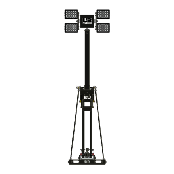
Will Burt NIGHT SCAN LITE Instructions Manual (84 pages)
MOBILE LIGHTING TOWER
Brand:
Will Burt
| Category:
Lighting Equipment
| Size: 4.54 MB
Table of Contents
Table of Contents
5
Safety Summary
9
Signal Word Definitions
9
General Safety Instructions
9
Symbols
12
Section 1 Introduction
13
Intended Use
13
Specification Compliance
14
CE Declaration of Conformity
14
National Fire Protection Agency NFPA 1901:2016 Compliance
16
Safety Precaution Notification
16
Manual Organization
16
Definitions of Terms
17
Mast System Specifications
17
Table 1-1 Night Scan Lite with RCP and Four X200 LED Lights
18
Table 1-2 Night Scan Lite with RCP and Two X200 LED Lights
19
Table 1-3 Night Scan Lite with RCP and no Lights
20
Table 1-4 Inflexion HD (no Rcp/No Lights)
21
Major Components
22
Mast Assembly
23
Figure 1-1 Mast Assembly
23
Figure 1-2 Remote Controlled Positioner with 4 X200 LED Lights
24
Remote Controlled Positioner (RCP) (P/N: 5532401)
24
X200 Lights (P/N: 5355406)
24
Figure 1-3 Top and Base Sections and Knuckle
25
Knuckle
25
RCP Cable
25
Top and Base Sections
25
Actuator (P/N: 5467502)
26
Figure 1-4 Support Struts, Actuator, and Gas Springs
26
Gas Springs (P/N: 5537701)
26
Support Struts
26
Base
27
Figure 1-5 Base and Saddle
27
Saddle
27
Control Box Assembly (P/N: 5551801)
28
Figure 1-6 Control Box Assembly
28
Figure 1-7 Identification Plate (P/N: 902852)
28
Identification Plate (P/N: 902852)
28
Look-Up Light (P/N: 214014)
28
Label Kit (English) (P/N: 5553501)
29
Junction Box (P/N: 5549701)
29
Hand-Held Remote Control (HHRC) (P/N: 5547101)
30
Junction Box Cable (P/N: 218103 Cut to Specified Length or P/N: 5563301 for 15-Meter (50 Ft.) Cable)
30
Figure 1-9 Hand-Held Remote Control
30
Accessory Options (Sold Separately)
31
Strobe/Beacon Lights
31
Cameras
31
Section 2 Installation
33
Pre-Installation Check
33
Installation Equipment
34
Table 2-1 Equipment Recommended for Installation
34
Installation Hardware
35
Installation Dimensions
35
Table 2-2 Installation Hardware
35
Figure 2-1 Mast System with RCP and Four X200 Lights
36
Figure 2-2 Mast System with RCP and Two X200 Lights
37
Figure 2-3 Mast System with RCP and no Lights
38
Figure 2-4 Mast System with no RCP and no Lights (Inflexion HD)
39
Power Supply Requirements
40
System Installation
41
Instructions for Night Scan Lite & Inflexion Hd
41
Physical Installation Detailed Instructions
41
Select a Suitable Mounting Location
42
Unpack the Night Scan Lite/Inflexion HD
42
Figure 2-5 Permissible Sling Points
43
Secure the Mast Assembly
44
Figure 2-6 Mast Assembly Mounting Holes
44
Secure the Junction Box
45
Install Additional Accessories (Optional)
45
Electrical Installation Detailed Instructions
46
Figure 2-7 Night Scan Lite System Customer Wiring Overview (Not to Scale)
46
Figure 2-8 Grounding Lug Location
46
Figure 2-9 Night Scan Lite Power Relay Wiring Diagram
47
Figure 2-10 Night Scan Lite Main Control Board Wiring Diagram
48
Figure 2-11 Night Scan Lite Remote Junction Box Wiring Diagram
49
Figure 2-12 Cable Locations
50
Partially Extend the Mast Manually
50
Figure 2-13 Junction Box Terminal Block
51
Wire Junction Box to Main Control Board
51
Figure 2-14 Main Control Board Terminal Blocks TB1 and TB2
52
Wire Vehicle Interlock on Sensor
52
Figure 2-15 Proximity Sensor
53
Figure 2-16 Vehicle Interlock Circuit Wiring Diagram
54
Wire Optional Auxiliary Devices to Power Relay Board
54
Figure 2-17 Power Relay Board Terminal Block TB6
55
Figure 2-18 Power Relay Board Terminal Block TB5
55
Wire Power for Optional Auxiliary Devices to Power Relay Board
55
Figure 2-19 Power Relay Board Terminal Block TB3
56
Wire Power for Lights or Payload to Power Relay Board
56
Figure 2-20 Payload Cable Routing
57
Figure 2-21 12VDC Input Power Wiring
58
Figure 2-22 Power Relay Board Terminal Block TB1
58
Wire Power for Mast and Control to Power Relay Board
58
Figure 2-23 Bulkhead Connector
59
Finalize Electrical Installation
59
Test the Installation
60
Install Payload
60
Figure 2-24 Mounting Hole Pattern
60
Figure 2-25 Inflexion HD Payload Saddle
61
Section 3 Operation
63
Pre-Operation Check
63
Operation Equipment
64
Table 3-1 Equipment Recommended for Operation
64
Controls
65
Operation
66
Quick Reference
66
Detailed Instructions
66
Initiate the System
66
Extend the Mast
67
Figure 3-1 Power LED
67
Figure 3-2 Positioner LED
67
Operate the RCP and Lights
68
Operate the Auxiliary Devices
68
Retract the Mast
69
Manual Operation of the Mast
70
Section 4 Transportation
71
General Transportation
71
Shipping
72
Section 5 Maintenance
73
Pre-Maintenance Check
73
Power Isolating Procedure
74
Maintenance Equipment
74
Table 5-1 Equipment Recommended for Maintenance
74
Spare Parts
75
Preventative Maintenance Schedule
75
Table 5-2 Preventative Maintenance Schedule
75
Cleaning the System
78
Section 6 Troubleshooting
79
Adjust RCP Saddles
80
Figure 6-1 RCP Saddles
80
Adjust Side Saddles
81
Figure 6-2 Side Saddle Wear Pads
81
Section 7 Reference
83
Extended Glossary of Terms
83
Figure 7-1 Extended
83
Disposal of Mast System
84
Figure 7-2 Nested
84
Advertisement
Advertisement
Related Products
Will Burt Night Scan Chief Series
Will Burt NIGHT SCAN VERTICAL
Will Burt Night Scan Vertical Complete
Will Burt Night Scan Vertical HDT
Will Burt Night Scan Powerlite Xtreme
Will Burt Night Scan Powerlite Heavy Duty Towing
Will Burt Night Scan Powerlite HDT
Will Burt Night Scan Powerlite Xtreme 6.0
Will Burt Night Scan Powerlite Xtreme 7.5
Will Burt Night Scan Powerlite 2.3
Will Burt Categories
Lighting Equipment
Antenna
Valve Positioners
Air Compressor
Racks & Stands
More Will Burt Manuals
Login
Sign In
OR
Sign in with Facebook
Sign in with Google
Upload manual
Upload from disk
Upload from URL