Table of Contents
Advertisement
Quick Links
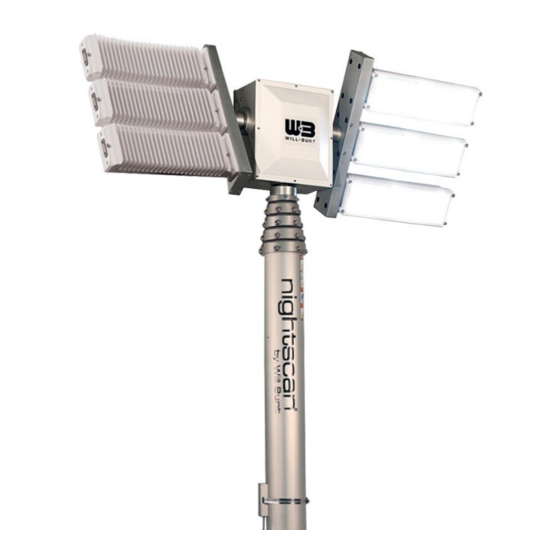
Night Scan Vertical, Night Scan Vertical Complete, and
Night Scan Vertical Heavy Duty Towing (HDT)
Night Scan Vertical Complete
The Will-Burt Company
401 Collins Blvd
Orrville, OH 44667, USA
Operating Instructions
Night Scan Vertical
Phone: +1 330 684 4000
E-Mail: info@willburt.com
Website: www.willburt.com
Authorized Representative:
Will-Burt Germany GmbH & Co. KG
Fischergasse 25
D-91344 Waischenfeld, Germany
Night Scan Vertical Heavy Duty Towing
TP-4836201-H, May 2021
© 2021 The Will-Burt Company
Original Instructions
Advertisement
Table of Contents
Troubleshooting

Related Manuals for Will Burt Night Scan Vertical 4.3-15


Summary of Contents for Will Burt Night Scan Vertical 4.3-15
- Page 1 Night Scan Vertical, Night Scan Vertical Complete, and Night Scan Vertical Heavy Duty Towing (HDT) Operating Instructions Night Scan Vertical Complete Night Scan Vertical Night Scan Vertical Heavy Duty Towing The Will-Burt Company Phone: +1 330 684 4000 TP-4836201-H, May 2021 401 Collins Blvd E-Mail: info@willburt.com ©...
- Page 3 NIGHT SCAN VERTICAL, VERTICAL COMPLETE, AND VERTICAL HDT OPERATING INSTRUCTIONS Warranty Will-Burt warrants its Night Scan Vertical to be free from defects in material and workmanship for a period of two (2) years, with such time period running from the date of shipment by Will-Burt. Will-Burt shall not be responsible for any damage resulting to or caused by its products by reason of failure to properly install, maintain or store the product;...
-
Page 4: Table Of Contents
NIGHT SCAN VERTICAL, VERTICAL COMPLETE, AND VERTICAL HDT OPERATING INSTRUCTIONS Contents 1 Safety Summary....................5 1.1 Signal Word Definitions..................... 5 1.2 Safety Instructions ....................5 1.3 Symbols Used on Product Labels................10 2 Specification Compliance ................. 13 2.1 NFPA 1901-2016 ....................13 2.2 CE Declaration of Conformity ................. - Page 5 NIGHT SCAN VERTICAL, VERTICAL COMPLETE, AND VERTICAL HDT OPERATING INSTRUCTIONS 5.10.1 Wiring Remote Control Cable to the Base Board ........62 5.10.2 Wiring Magnetic Switches to the Base Board ..........62 5.10.3 Wiring DC Source Power to the Mast Control Circuit ......... 63 5.10.4 Wiring Source Power to the Lighting Circuits..........
- Page 6 NIGHT SCAN VERTICAL, VERTICAL COMPLETE, AND VERTICAL HDT OPERATING INSTRUCTIONS 11.2.2 Night Scan Vertical Complete Drawings ........... 118 11.2.3 Night Scan Vertical Heavy Duty Towing (HDT) Drawings ......122 PAGE 4 OF 126 TP-4836201-H MAY 2021...
-
Page 7: Safety Summary
NIGHT SCAN VERTICAL, VERTICAL COMPLETE, AND VERTICAL HDT OPERATING INSTRUCTIONS Safety Summary This section describes safety instructions for the Night Scan Vertical that personnel must understand and apply throughout all product activities such as transportation, handling, installation, operation, maintenance, storage, disposal and troubleshooting. Read and understand this entire document, and contact The Will-Burt Company with any questions, before performing any procedure outlined in this document. - Page 8 NIGHT SCAN VERTICAL, VERTICAL COMPLETE, AND VERTICAL HDT OPERATING INSTRUCTIONS environmental conditions, including, but not limited to, mast size and weight, payload and cable size and weight, payload sail area, wind speed, guy line arrangement, support bracket or roof line location, and base plate assembly. Do not operate in wind speed conditions exceeding the maximum rated wind speed.
- Page 9 NIGHT SCAN VERTICAL, VERTICAL COMPLETE, AND VERTICAL HDT OPERATING INSTRUCTIONS and maintenance to be performed by trained and authorized personnel only. Only a properly trained and qualified certified electrician should perform electric installations and service. Erratic Mast Operation Impact Hazard! The mast should operate smoothly during extension and retraction.
- Page 10 NIGHT SCAN VERTICAL, VERTICAL COMPLETE, AND VERTICAL HDT OPERATING INSTRUCTIONS Fire Hazard Solvent! Cleaning solvent, used for maintenance, is flammable and can be explosive. Do not smoke near solvent. Use cleaning solvent in a well-ventilated area. Keep cleaning solvent away from ignition sources. Always store cleaning solvent in the proper marked container and in a proper location.
- Page 11 NIGHT SCAN VERTICAL, VERTICAL COMPLETE, AND VERTICAL HDT OPERATING INSTRUCTIONS Safety Instruction - Potential Air Contaminants! If internally mounted in a vehicle, air from mast and any accumulated water will discharge into the vehicle. Install appropriate drainage and venting. Fastener Vibration Hazard! Mast system and payload mounting hardware must include proper means to resist vibration loosening such as thread-locking compound, locking hardware, or equivalent.
-
Page 12: Symbols Used On Product Labels
NIGHT SCAN VERTICAL, VERTICAL COMPLETE, AND VERTICAL HDT OPERATING INSTRUCTIONS Manual Tilt! If manually tilting mast, make sure all power has been disconnected from the sys- tem prior to manually lowering mast to avoid unexpected motion and/or damaging mast compo- nents. - Page 13 NIGHT SCAN VERTICAL, VERTICAL COMPLETE, AND VERTICAL HDT OPERATING INSTRUCTIONS This symbol is used to indicate the center of gravity (COG) of a fully nested mast in a horizontal transport position. TP-4836201-H PAGE 11 OF 126 MAY 2021...
- Page 14 NIGHT SCAN VERTICAL, VERTICAL COMPLETE, AND VERTICAL HDT OPERATING INSTRUCTIONS PAGE 12 OF 126 TP-4836201-H MAY 2021...
-
Page 15: Specification Compliance
NIGHT SCAN VERTICAL, VERTICAL COMPLETE, AND VERTICAL HDT OPERATING INSTRUCTIONS Specification Compliance NFPA 1901-2016 The mast system is designed to be compliant with the following sections of National Fire Protection Agency NPFA-1901-2016 Edition: 22.14 Powered Operated Light Masts 23.13 Power Operated Masts CE Declaration of Conformity Refer to the Product page at www.willburt.com for the latest Declaration of Conformity. - Page 16 NIGHT SCAN VERTICAL, VERTICAL COMPLETE, AND VERTICAL HDT OPERATING INSTRUCTIONS PAGE 14 OF 126 TP-4836201-H MAY 2021...
-
Page 17: Introduction
The views depicted in this manual are provided for clarification and are subject to change without notice. Views are not to scale. The following models are covered in these operating instructions: • Night Scan Vertical 4.3-15 (1.35-4.08 meters) • Night Scan Vertical 5.4-17 (1.62-5.18 meters) • Night Scan Vertical 6-20 (1.83-6.1 meters) •... -
Page 18: Intended Use
NIGHT SCAN VERTICAL, VERTICAL COMPLETE, AND VERTICAL HDT OPERATING INSTRUCTIONS Intended Use The Night Scan Vertical, Night Scan Vertical Complete, and Night Scan Vertical HDT are intended for use by professionals in the fire/rescue/first responder/security/towing industries to provide elevated and directional emergency scene lighting and surveillance or communication capabilities. -
Page 19: Mast Component Descriptions
NIGHT SCAN VERTICAL, VERTICAL COMPLETE, AND VERTICAL HDT OPERATING INSTRUCTIONS Mast Component Descriptions Figure 3-2 shows major components of the Night Scan Vertical system. Figure 3-3 shows major components of the Night Scan Vertical Complete system. Figure 3-4 shows major components of the Night Scan Vertical HDT system. - Page 20 NIGHT SCAN VERTICAL, VERTICAL COMPLETE, AND VERTICAL HDT OPERATING INSTRUCTIONS Light Light Bar Tube Section Collars Upper Magnetic Switch Saddle Mast Lower Magnetic Switch Adjustable Mounting Plate (Optional) Solenoid Valve Assembly Control Box Base Assembly Figure 3-4 Night Scan Vertical HDT (Model 72030005 shown) Mast: The mast consists of concentric tube sections that extend as air pressure is applied.
- Page 21 NIGHT SCAN VERTICAL, VERTICAL COMPLETE, AND VERTICAL HDT OPERATING INSTRUCTIONS Mounting Hardware: Your system may come with either internal or external mounting hardware. Note: Night Scan Vertical Complete mounting hardware is customer-provided. Internal: The internal mounting kit (Figure 3-6) contains the brackets and seals used to position and support an internally mounted mast.
- Page 22 NIGHT SCAN VERTICAL, VERTICAL COMPLETE, AND VERTICAL HDT OPERATING INSTRUCTIONS The base plate attaches to the mounting structure by screwing four bolts through the base plate and mounting structure. Shelf Bracket: An optional shelf bracket (Figure 3-9) is available to support the mast base. The base plate attaches to the shelf bracket.
- Page 23 NIGHT SCAN VERTICAL, VERTICAL COMPLETE, AND VERTICAL HDT OPERATING INSTRUCTIONS Control Box: The control box (Figure 3-11, Figure 3-12, Figure 3-13) contains the base board for the system, and the solenoid valve assembly. This is where power and air supply are connected.
- Page 24 NIGHT SCAN VERTICAL, VERTICAL COMPLETE, AND VERTICAL HDT OPERATING INSTRUCTIONS 14/4 Light Power Cable HHRC Bulkhead Cable 18/2 Base Board Solenoid Power 12/2 Control Power Magnetic Switches from Mast and Valve Assembly Coil Cord from Mast Figure 3-13 Night Scan Vertical HDT Control Box (Front Cover Removed) Base Board: The PC Board (PCB) contains the system logical controller and provides landing points for customer power supply and vehicle interlock cables.
- Page 25 NIGHT SCAN VERTICAL, VERTICAL COMPLETE, AND VERTICAL HDT OPERATING INSTRUCTIONS Lights: The Night Scan Vertical systems and Night Scan Vertical Complete systems can come with a variety of LED or Halogen lighting packages. Night Scan Vertical HDT systems ship with Will-Burt XL-160 LED lights.
- Page 26 NIGHT SCAN VERTICAL, VERTICAL COMPLETE, AND VERTICAL HDT OPERATING INSTRUCTIONS Base Assembly: The base assembly is connected to the mast and is used to secure the vertical HDT to the mounting structure (Figure 3-15). The optional adjustable mounting plate can assist in securing the mast.
-
Page 27: Remote Control Options
NIGHT SCAN VERTICAL, VERTICAL COMPLETE, AND VERTICAL HDT OPERATING INSTRUCTIONS Remote Control Options There are three options for controlling the mast functions. Each option provides full system control. These controllers all have two-way communication with the system and LED display that include alphanumeric feedback. - Page 28 NIGHT SCAN VERTICAL, VERTICAL COMPLETE, AND VERTICAL HDT OPERATING INSTRUCTIONS Ground Wire (Attached to Bulkhead) 7-pin Connector Control Cable (Attached to Bulkhead) Figure 3-17 HHRC Bulkhead Connection PAGE 26 OF 126 TP-4836201-H MAY 2021...
-
Page 29: Technical Data
NIGHT SCAN VERTICAL, VERTICAL COMPLETE, AND VERTICAL HDT OPERATING INSTRUCTIONS Technical Data Night Scan Vertical Vertical Vertical 4.3-15 5.4-17 6-20 7-25 8-30 Complete Extended Height (ft / m) 13.4 / 4.08 17 / 5.2 20.4 / 6.2 25.4 / 7.7 30.4 / 9.2 7.5 / 2.3 15 / 4.5 Nested Height (ft / m) 4.5 / 1.3 5.5 / 1.68 6.1 / 1.9 7.1 / 2.2 8.1 / 2.5... - Page 30 NIGHT SCAN VERTICAL, VERTICAL COMPLETE, AND VERTICAL HDT OPERATING INSTRUCTIONS PAGE 28 OF 126 TP-4836201-H MAY 2021...
-
Page 31: Installation
NIGHT SCAN VERTICAL, VERTICAL COMPLETE, AND VERTICAL HDT OPERATING INSTRUCTIONS Installation This section describes the physical and electrical installation of the Night Scan Vertical, Night Scan Vertical Complete, and Night Scan Vertical Heavy Duty Towing (HDT) mast systems. This section provides the general procedures that must be followed to ensure a successful installation. -
Page 32: Dimensions
NIGHT SCAN VERTICAL, VERTICAL COMPLETE, AND VERTICAL HDT OPERATING INSTRUCTIONS 3. The roof-line for internally mounted masts or the support bracket for externally mounted masts must lie between the weep hole and base tube collar. Mounting hardware should be at least 1 inch (25 mm) above the weep hole and 3 inches (76 mm) below the collar. -
Page 33: Recommended Installation Tools
NIGHT SCAN VERTICAL, VERTICAL COMPLETE, AND VERTICAL HDT OPERATING INSTRUCTIONS Recommended Installation Tools Table 5-2 lists recommended tools and materials for installation. Table 5-2 Recommended Installation Tools & Materials Tools and Materials Safety Glasses Safety Gloves Safety Shoes Hard Hat or Helmet Hearing Protection Crimping Tool or Solder Set Wrenches... - Page 34 NIGHT SCAN VERTICAL, VERTICAL COMPLETE, AND VERTICAL HDT OPERATING INSTRUCTIONS Table 5-3 Components in the Mast Unit Ship Components Night Scan Vertical Mounting Kit (Internal Mast Base Plate Saddle Kit or External) Controller (Selected from the following:) Mast Control Power •...
- Page 35 NIGHT SCAN VERTICAL, VERTICAL COMPLETE, AND VERTICAL HDT OPERATING INSTRUCTIONS 4. Inspect for any shipping damage. If damage has occurred, notify the carrier. 5. Unbolt (for wooden crates) and remove any banding fixing the mast to the shipping crate or carton.
-
Page 36: Attaching To The Vehicle
NIGHT SCAN VERTICAL, VERTICAL COMPLETE, AND VERTICAL HDT OPERATING INSTRUCTIONS Attaching to the Vehicle Read and understand all the mounting requirements in Section 5.1. Note: The only section in Section 5.4 that applies to the Night Scan Vertical Complete is Section 5.4.2. -
Page 37: Night Scan Vertical Complete Mounting Instructions
NIGHT SCAN VERTICAL, VERTICAL COMPLETE, AND VERTICAL HDT OPERATING INSTRUCTIONS 5.4.2 Night Scan Vertical Complete Mounting Instructions Physically attach the system as follows: 1. Ensure that the control box, mast, and saddle are on a flat surface and in the same plane. Switches set at the factory are based on a level surface. -
Page 38: Night Scan Vertical Hdt Mounting Instructions
NIGHT SCAN VERTICAL, VERTICAL COMPLETE, AND VERTICAL HDT OPERATING INSTRUCTIONS Figure 5-4 Night Scan Vertical Complete Mounting Hole Locations (Control Box Mounted to the Side of the Mast) 5.4.3 Night Scan Vertical HDT Mounting Instructions Physically attach the system as follows: 1. -
Page 39: Attach Internal Mounting Kit
NIGHT SCAN VERTICAL, VERTICAL COMPLETE, AND VERTICAL HDT OPERATING INSTRUCTIONS 5.4.4 Attach Internal Mounting Kit This section describes the installation for the internal mounting kit. If your mast is externally mounted, you can skip to the next section. The roof-line for internally mounted masts should be as flat as possible where the mast mounts. The roof-line must lie between the weep hole and base tube collar. - Page 40 NIGHT SCAN VERTICAL, VERTICAL COMPLETE, AND VERTICAL HDT OPERATING INSTRUCTIONS 3. If necessary, use washers or short spacers made of ¼ inch (6.35 mm) pipe to level out any irregularities that exist in the roof. 4. Place the gasket on the roof and align the mounting holes. 5.
-
Page 41: Attach The Base Plate To The Mast
NIGHT SCAN VERTICAL, VERTICAL COMPLETE, AND VERTICAL HDT OPERATING INSTRUCTIONS 9. Loosely install six user provided 1/4 inch or M6 bolts, lock washers and hex nuts to secure the internal mounting kit bracket to the roof. Bolt length depends on the specific application and is to be determined by the installer. -
Page 42: Attach The Base Plate To The Vehicle
NIGHT SCAN VERTICAL, VERTICAL COMPLETE, AND VERTICAL HDT OPERATING INSTRUCTIONS 5.4.6 Attach the Base Plate to the Vehicle Before final tightening of the base plate bolts, it is recommended to install the support bracket or roof mount kit loosely before final tightening to ensure alignment of all components. Once alignment is achieved, all bolts can be tightened according to these instructions. -
Page 43: Attach The Support Bracket
NIGHT SCAN VERTICAL, VERTICAL COMPLETE, AND VERTICAL HDT OPERATING INSTRUCTIONS 5.4.7 Attach the Support Bracket This section describes the installation of the external support bracket. For external mounting, the base plate and support bracket should be fitted loosely with all fasteners installed to ensure everything aligns. -
Page 44: Attach Optional Shelf Bracket
NIGHT SCAN VERTICAL, VERTICAL COMPLETE, AND VERTICAL HDT OPERATING INSTRUCTIONS 5.4.8 Attach Optional Shelf Bracket If using the optional shelf bracket, the mast base plate is installed on the shelf bracket instead of the vehicle structure following section 5.4.6. The shelf bracket attaches to the vehicle structure using the following steps: 1. - Page 45 NIGHT SCAN VERTICAL, VERTICAL COMPLETE, AND VERTICAL HDT OPERATING INSTRUCTIONS Figure 5-9 Shelf Bracket Installation Dimensions TP-4836201-H PAGE 43 OF 126 MAY 2021...
-
Page 46: Attach The Rcp Saddle Brackets
NIGHT SCAN VERTICAL, VERTICAL COMPLETE, AND VERTICAL HDT OPERATING INSTRUCTIONS 5.4.9 Attach the RCP Saddle Brackets The RCP saddle brackets (Figure 5-10) must be installed to support the lights and RCP when the mast is nested and the vehicle is in transit. The brackets are adjustable in height to obtain the proper position to allow the RCP to rest against the saddle brackets when nesting. -
Page 47: Night Scan Vertical
NIGHT SCAN VERTICAL, VERTICAL COMPLETE, AND VERTICAL HDT OPERATING INSTRUCTIONS 5.4.9.1 Night Scan Vertical To attach the RCP saddle brackets: 1. Drill six mounting holes into the mounting structure according to Figure 5-11. The brackets can be used as a template to mark locations. 2. - Page 48 NIGHT SCAN VERTICAL, VERTICAL COMPLETE, AND VERTICAL HDT OPERATING INSTRUCTIONS Figure 5-12 Mounting Variations. Clockwise from upper left: Saddle Deck Mount; Saddle Wall Mount; Saddle and RCP Assembly Lights Stowed Horizontally; Saddle and RCP Lights Stowed Vertically PAGE 46 OF 126 TP-4836201-H MAY 2021...
-
Page 49: Night Scan Vertical Hdt
NIGHT SCAN VERTICAL, VERTICAL COMPLETE, AND VERTICAL HDT OPERATING INSTRUCTIONS 5.4.9.2 Night Scan Vertical HDT To attach the RCP saddle brackets: 1. Drill eight mounting holes into the mounting structure according to Figure 5-13. The brackets can be used as a template to mark locations. 2. -
Page 50: Attaching The Control Box
NIGHT SCAN VERTICAL, VERTICAL COMPLETE, AND VERTICAL HDT OPERATING INSTRUCTIONS Attaching the Control Box 5.5.1 Night Scan Vertical The control box may be surface mounted using four M6 or 1/4 inch screws, nuts, and lock washers provided by the installer. To install the control box: 1. -
Page 51: Night Scan Vertical Hdt
NIGHT SCAN VERTICAL, VERTICAL COMPLETE, AND VERTICAL HDT OPERATING INSTRUCTIONS 5.5.3 Night Scan Vertical HDT The control box may be surface mounted using four ¼ inch or M6 screws, nuts, and lock washers provided by the installer. To install the control box: 1. -
Page 52: Attaching The Air Connections
NIGHT SCAN VERTICAL, VERTICAL COMPLETE, AND VERTICAL HDT OPERATING INSTRUCTIONS Attaching the Air Connections 5.6.1 Night Scan Vertical Source air may be supplied externally by a compressor or other source of clean, dry air with a maximum pressure of 6.9 bar (100 psi). The source air should be attached to the port on the control box labeled “Air - Inlet”... - Page 53 NIGHT SCAN VERTICAL, VERTICAL COMPLETE, AND VERTICAL HDT OPERATING INSTRUCTIONS Mast Coil Cord HHRC DC Control Light Power Air Exhaust Air Inlet Air to Mast Air to Mast Air Exhaust Figure 5-16 Control Box Valve Layout (Cover Removed) Figure 5-17 Mast Air Inlet Hardware Kit Assembly Detail TP-4836201-H PAGE 51 OF 126 MAY 2021...
-
Page 54: Night Scan Vertical Complete
NIGHT SCAN VERTICAL, VERTICAL COMPLETE, AND VERTICAL HDT OPERATING INSTRUCTIONS 5.6.2 Night Scan Vertical Complete The Night Scan Vertical Complete operates with an air compressor, which arrives already installed. This means that there is no air connection setup required. 5.6.3 Night Scan Vertical HDT Air may be supplied externally by a compressor or other source of clean, dry air with a maximum pressure of 6.9 bar (100 psi). - Page 55 NIGHT SCAN VERTICAL, VERTICAL COMPLETE, AND VERTICAL HDT OPERATING INSTRUCTIONS Figure 5-18 Night Scan Vertical HDT Valve Assembly Figure 5-19 Mast Air Inlet Hardware Kit Assembly Detail TP-4836201-H PAGE 53 OF 126 MAY 2021...
-
Page 56: Attaching The Rcp To The Mast
NIGHT SCAN VERTICAL, VERTICAL COMPLETE, AND VERTICAL HDT OPERATING INSTRUCTIONS Attaching the RCP to the Mast To attach the RCP to the mast: 1. Ensure the power is off. ® Note: The RCP is not shipped in the Auto Stow position for the light tilt angle. -
Page 57: Installing The Magnetic Switches
NIGHT SCAN VERTICAL, VERTICAL COMPLETE, AND VERTICAL HDT OPERATING INSTRUCTIONS Installing the Magnetic Switches Note: The magnetic switches contain Reed switches made from glass tubes that can be damaged under high impact loading due to handling. This requires the installer to be careful when handing the switches. - Page 58 NIGHT SCAN VERTICAL, VERTICAL COMPLETE, AND VERTICAL HDT OPERATING INSTRUCTIONS Attach the bottom switch toward the bottom of the mast, again noting the proper orientation shown in Figure 5-21. The final height of this switch will be adjusted after the control systems are wired and powered up (see Section 5.10.7).
-
Page 59: Attaching The Power Converter
NIGHT SCAN VERTICAL, VERTICAL COMPLETE, AND VERTICAL HDT OPERATING INSTRUCTIONS 5.8.1 Attaching the Power Converter Note: The Power Converter is standard with the Night Scan Vertical HDT, but it is optional for the Night Scan Vertical and Night Scan Vertical Complete. Mount the power converter vertically (fins up and down) for better heat dissipation (Figure 5-22). - Page 60 NIGHT SCAN VERTICAL, VERTICAL COMPLETE, AND VERTICAL HDT OPERATING INSTRUCTIONS To attach the bulkhead: 1. Drill clearance holes for 1/4-20 screws located per Figure 5-23. Either two hole pattern can be selected according to the space available. 2. Using the screws, washers, and nuts provided, attach the bulkhead to the vehicle. Torque the 1/4-20 screws to 62-70 in.-lb.
-
Page 61: Panel Mount Remote Control (Pmrc)
NIGHT SCAN VERTICAL, VERTICAL COMPLETE, AND VERTICAL HDT OPERATING INSTRUCTIONS The HHRC comes with a holder (see Figure 5-24) to hang the HHRC. Attach the HHRC holder at a convenient location to hang the HHRC in a dry, protected environment. To install the holder: 1. -
Page 62: Wireless Remote Control
NIGHT SCAN VERTICAL, VERTICAL COMPLETE, AND VERTICAL HDT OPERATING INSTRUCTIONS Figure 5-25 PMRC Panel Cutout Dimensions A loose wiring connector is shipped with the PMRC to allow cable routing in the vehicle. Once the cable is routed, wire the connector and attach the connector to the back of the PMRC. To wire the PMRC connector: 1. -
Page 63: 5.10 Electrical Installation Detail
NIGHT SCAN VERTICAL, VERTICAL COMPLETE, AND VERTICAL HDT OPERATING INSTRUCTIONS 5.10 Electrical Installation Detail Ensure the source power for the mast and lights is not connected or turned off before wiring the system following proper lock-out tag-out procedures. See Figure 3-11, Figure 3-12, Figure 3-13, and Figure 5-16 for information on where the cables run into the control box. -
Page 64: Wiring Remote Control Cable To The Base Board
NIGHT SCAN VERTICAL, VERTICAL COMPLETE, AND VERTICAL HDT OPERATING INSTRUCTIONS 5.10.1 Wiring Remote Control Cable to the Base Board The bulkhead cable (or PMRC Control Cable) connects the bulkhead, remote control, and base board. Route the cable through the cable grip labeled HHRC in Figure 5-16. Then connect the wires from the bulkhead cable (or PMRC Control Cable) to the green J4 connector located on the top left of the base board, ensuring the wires match the color strip on the J4 connector and the wiring diagram. -
Page 65: Wiring Dc Source Power To The Mast Control Circuit
NIGHT SCAN VERTICAL, VERTICAL COMPLETE, AND VERTICAL HDT OPERATING INSTRUCTIONS 5.10.3 Wiring DC Source Power to the Mast Control Circuit The mast control system requires DC power regardless of what power is required by the lighting circuits (AC or DC). Source DC power is provided by the installer from the vehicle battery. The mast system will operate with 12VDC or 24VDC source power. - Page 66 NIGHT SCAN VERTICAL, VERTICAL COMPLETE, AND VERTICAL HDT OPERATING INSTRUCTIONS Table 5-4 shows some example current calculations. Your mast may have different results based on the installed light type and number of lights. In Example 1 (Table 5-4), the lights in the system are a total of 500 watts.
-
Page 67: Wiring Vehicle Safety Interconnect Circuit
NIGHT SCAN VERTICAL, VERTICAL COMPLETE, AND VERTICAL HDT OPERATING INSTRUCTIONS 5.10.5 Wiring Vehicle Safety Interconnect Circuit The mast provides an isolated relay contact output to enhance integration into vehicle safety circuitry. This output indicates whether or not the mast is stowed to indicate it is safe to move the vehicle. -
Page 68: Power-Up And Magnetic Switch Adjustment
NIGHT SCAN VERTICAL, VERTICAL COMPLETE, AND VERTICAL HDT OPERATING INSTRUCTIONS 5.10.7 Power-up and Magnetic Switch Adjustment Note: When applying power to the mast for the first time, it is possible the light fixtures will rotate (tilt) to the stowed position. Stay clear from the light fixtures during power-up. Once all wiring connections have been made, apply DC power to the mast control system. -
Page 69: 5.11 Test The Installation
NIGHT SCAN VERTICAL, VERTICAL COMPLETE, AND VERTICAL HDT OPERATING INSTRUCTIONS 5.11 Test the Installation Review the Operation (Section 6) and the Safety Summary (Section 1) sections and observe all safety dangers, warnings, and cautions before proceeding to test the installation. If any part of the testing fails, check the LEDs on the controller and base board. - Page 70 NIGHT SCAN VERTICAL, VERTICAL COMPLETE, AND VERTICAL HDT OPERATING INSTRUCTIONS 13. Rapidly press the “Mast-Down” button two times to invoke the Auto Stow® feature that places the mast into the saddle and turns power off. Confirm the power automatically turns off when nested.
-
Page 71: Operation
NIGHT SCAN VERTICAL, VERTICAL COMPLETE, AND VERTICAL HDT OPERATING INSTRUCTIONS Operation This section describes the operation of the system. Be sure to read and understand the entire operation procedure and the Safety Summary (Section 1) before beginning operation. Pre-Operation Check Before operating the system: 1. -
Page 72: Quick Operation Summary
NIGHT SCAN VERTICAL, VERTICAL COMPLETE, AND VERTICAL HDT OPERATING INSTRUCTIONS Quick Operation Summary The following is a quick summary of the operation of the system. Detailed steps follow the quick summary. If an emergency stop (E-Stop) is required at any time, press the “E-Stop” button. This disconnects the unit from power and causes all air to be exhausted from the mast. -
Page 73: Initiating (Power-Up)
NIGHT SCAN VERTICAL, VERTICAL COMPLETE, AND VERTICAL HDT OPERATING INSTRUCTIONS Initiating (Power-Up) On initiation, the base board establishes communication with the other boards in the system. If communication cannot be established, an error code is shown on the display and the communication system is shut down. -
Page 74: Stowing The Mast
NIGHT SCAN VERTICAL, VERTICAL COMPLETE, AND VERTICAL HDT OPERATING INSTRUCTIONS Stowing the Mast The "stowed" position is also called the "nested" position. The stowed position is the position of the mast when it is fully lowered and firmly seated in the saddle. The mast is considered stowed when the Mast Stowed Switch (lower magnetic switch) is closed and the mast powers-off. -
Page 75: Using The Mast Down Button
NIGHT SCAN VERTICAL, VERTICAL COMPLETE, AND VERTICAL HDT OPERATING INSTRUCTIONS 6.8.2 Using the Mast Down Button Another method used to stow the mast is to press and hold "Mast Down" on the controller. This method is not as reliable as using the Auto Stow® feature. Care must be taken to ensure that the operator does not release the button before the mast is completely stowed. -
Page 76: Emergency Stow With Power
NIGHT SCAN VERTICAL, VERTICAL COMPLETE, AND VERTICAL HDT OPERATING INSTRUCTIONS 6.8.3 Emergency Stow with Power If the mast cannot be stowed using the Auto Stow® feature or "Mast Down" button, the emergency stow button (S4) on the base board can be used to stow the mast if the following are both true: •... -
Page 77: Maintenance, Adjustments And Disposal
NIGHT SCAN VERTICAL, VERTICAL COMPLETE, AND VERTICAL HDT OPERATING INSTRUCTIONS Maintenance, Adjustments and Disposal This section describes the routine maintenance and adjustment procedures required to keep your system operational. Be sure to read and understand the entire operation procedure (Section 6) and the Safety Summary (Section 1) before beginning any maintenance or adjustment procedure. -
Page 78: Spare Parts
NIGHT SCAN VERTICAL, VERTICAL COMPLETE, AND VERTICAL HDT OPERATING INSTRUCTIONS To clean the system: 1. Wipe down the Remote-Controlled Positioner (RCP) using a soft cloth or sponge and a mild solution of soapy water. 2. After light fixtures cool, clean the light lenses using a soft cloth and standard glass cleaner. After cleaning the mast, if the mast is in extremely harsh environmental conditions, lubricate the mast with TMD Mast Lubricant (P/N: 900600). -
Page 79: Periodic Inspections
NIGHT SCAN VERTICAL, VERTICAL COMPLETE, AND VERTICAL HDT OPERATING INSTRUCTIONS Periodic Inspections This section describes the systematic care and inspection of equipment to keep it in safe operating condition and to prevent breakdowns. If the system does not perform as required, see Section 9 for troubleshooting. -
Page 80: Adjusting The Mast Magnetic Switches
NIGHT SCAN VERTICAL, VERTICAL COMPLETE, AND VERTICAL HDT OPERATING INSTRUCTIONS Table 7-1 Periodic Inspections (Continued) Frequency Inspection Action With the mast fully nested, check to If the joint is loose, adjust the ensure the RCP is firmly in contact Every 6 Months saddle height according to Section with the saddle and there is no 5.4.9... - Page 81 NIGHT SCAN VERTICAL, VERTICAL COMPLETE, AND VERTICAL HDT OPERATING INSTRUCTIONS Upper Magnetic Switch Lower Magnetic Switch Control Box Attached Below Mast Control Box Attached to Side of Mast Figure 7-2 Night Scan Vertical Complete Upper and Lower Magnetic Switches Upper Magnetic Switch Lower Magnetic Switch Figure 7-3 Night Scan Vertical Heavy Duty Towing (HDT) Upper and Lower Magnetic Switches Follow the instructions in Section 5.10.2 and Section 5.10.7 for adjusting the Magnetic Switch...
-
Page 82: Adjusting The Rcp Home Position
NIGHT SCAN VERTICAL, VERTICAL COMPLETE, AND VERTICAL HDT OPERATING INSTRUCTIONS Adjusting the RCP Home Position The RCP home position is the position of the RCP and lights where the light bars align with the saddle and the lights are facing down when stowed. If the RCP home position is set properly, when being stowed, the RCP shafts should contact the saddle simultaneously. - Page 83 NIGHT SCAN VERTICAL, VERTICAL COMPLETE, AND VERTICAL HDT OPERATING INSTRUCTIONS 3. Remove the RCP cover to access the flags. The pan and tilt flags are attached to the timing rings on the horizontal and vertical shaft gears (Figure 7-4). The tilt timing ring has two set screws that must be loosened.
- Page 84 NIGHT SCAN VERTICAL, VERTICAL COMPLETE, AND VERTICAL HDT OPERATING INSTRUCTIONS 6. To set the Pan Home Position, turn the flag counterclockwise (looking from above the RCP) until the "Pan Right" LED goes out (see Figure 7-5). Tighten the adjustment screws to secure the ring.
-
Page 85: Dual-Tilt Rcp Home Position Adjustment
NIGHT SCAN VERTICAL, VERTICAL COMPLETE, AND VERTICAL HDT OPERATING INSTRUCTIONS 7.5.2 Dual-Tilt RCP Home Position Adjustment If an adjustment is required, adjust the RCP home position as follows: 1. Disconnect all light power to the system using proper lock-out tag-out procedures (see Section 7.1). -
Page 86: System Disposal
NIGHT SCAN VERTICAL, VERTICAL COMPLETE, AND VERTICAL HDT OPERATING INSTRUCTIONS 7. Tilt the unit until the second set screw for the tilt flag is accessible. Tighten the second set screw. 8. Stow the mast, watching for the RCP and lights to become oriented as described in the beginning of this section. -
Page 87: Reference Information
NIGHT SCAN VERTICAL, VERTICAL COMPLETE, AND VERTICAL HDT OPERATING INSTRUCTIONS Reference Information This section describes reference information for your system, including some optional equipment. DIP Switch Definitions Dual In-Line Package (DIP) Switches on the base board and the Remote-Controlled Positioner (RCP) PC board are set at the factory and normally do not have to be changed. -
Page 88: Strobe/Beacon Light
NIGHT SCAN VERTICAL, VERTICAL COMPLETE, AND VERTICAL HDT OPERATING INSTRUCTIONS Strobe/Beacon Light The optional strobe/beacon light (Figure 8-1) provides visibility and safety by mounting on top the RCP and brightly showing the height of the mast. The strobe/beacon light can be used at any voltage from 12 to 48 VDC. -
Page 89: D-Tec® Sensor
NIGHT SCAN VERTICAL, VERTICAL COMPLETE, AND VERTICAL HDT OPERATING INSTRUCTIONS D-TEC® Sensor The D-TEC® Sensor is an optional accessory that is mounted on the backside of the RCP to detect and prevent operation near power lines. The D-TEC® Sensor senses electric field strength and prevents the mast from raising if the field strength is above the alarm threshold. -
Page 90: D-Tec® Functionality
NIGHT SCAN VERTICAL, VERTICAL COMPLETE, AND VERTICAL HDT OPERATING INSTRUCTIONS 8.3.2 D-TEC® Functionality The optional D-TEC® Sensor provides additional limited protection against raising the mast into power lines. On Night Scan fold-down units, as soon as the mast begins tilting, the control begins initiating the D-TEC®... - Page 91 NIGHT SCAN VERTICAL, VERTICAL COMPLETE, AND VERTICAL HDT OPERATING INSTRUCTIONS The D-TEC® Sensor is not serviceable, so most issues will end with returning the sensor to The Will-Burt Company for repair. The following table shows D-TEC® error code meanings: Table 8-3 D-TEC® Sensor Error Codes Message Meaning Root Issue...
-
Page 92: Nycoil® (Optional)
NIGHT SCAN VERTICAL, VERTICAL COMPLETE, AND VERTICAL HDT OPERATING INSTRUCTIONS Table 8-3 D-TEC® Sensor Error Codes (Continued) Message Meaning Root Issue Potential Cause The power supply section of the D-TEC® Supply Voltage Check power connections, voltage level 5,16 sensor is Fault and induced noise on power source. - Page 93 NIGHT SCAN VERTICAL, VERTICAL COMPLETE, AND VERTICAL HDT OPERATING INSTRUCTIONS TP-4836201-H PAGE 91 OF 126 MAY 2021...
- Page 94 NIGHT SCAN VERTICAL, VERTICAL COMPLETE, AND VERTICAL HDT OPERATING INSTRUCTIONS PAGE 92 OF 126 TP-4836201-H MAY 2021...
- Page 95 NIGHT SCAN VERTICAL, VERTICAL COMPLETE, AND VERTICAL HDT OPERATING INSTRUCTIONS TP-4836201-H PAGE 93 OF 126 MAY 2021...
- Page 96 NIGHT SCAN VERTICAL, VERTICAL COMPLETE, AND VERTICAL HDT OPERATING INSTRUCTIONS PAGE 94 OF 126 TP-4836201-H MAY 2021...
- Page 97 NIGHT SCAN VERTICAL, VERTICAL COMPLETE, AND VERTICAL HDT OPERATING INSTRUCTIONS TP-4836201-H PAGE 95 OF 126 MAY 2021...
- Page 98 NIGHT SCAN VERTICAL, VERTICAL COMPLETE, AND VERTICAL HDT OPERATING INSTRUCTIONS PAGE 96 OF 126 TP-4836201-H MAY 2021...
-
Page 99: The Will-Burt Company Mast Oil Safety Data Sheet
NIGHT SCAN VERTICAL, VERTICAL COMPLETE, AND VERTICAL HDT OPERATING INSTRUCTIONS The Will-Burt Company Mast Oil Safety Data Sheet TP-4836201-H PAGE 97 OF 126 MAY 2021... - Page 100 NIGHT SCAN VERTICAL, VERTICAL COMPLETE, AND VERTICAL HDT OPERATING INSTRUCTIONS PAGE 98 OF 126 TP-4836201-H MAY 2021...
- Page 101 NIGHT SCAN VERTICAL, VERTICAL COMPLETE, AND VERTICAL HDT OPERATING INSTRUCTIONS TP-4836201-H PAGE 99 OF 126 MAY 2021...
- Page 102 NIGHT SCAN VERTICAL, VERTICAL COMPLETE, AND VERTICAL HDT OPERATING INSTRUCTIONS PAGE 100 OF 126 TP-4836201-H MAY 2021...
-
Page 103: Troubleshooting
NIGHT SCAN VERTICAL, VERTICAL COMPLETE, AND VERTICAL HDT OPERATING INSTRUCTIONS Troubleshooting This section describes system troubleshooting information. Please contact The Will-Burt Company if these guides do not solve the issue. Be sure to read and understand the entire operation procedure and the Safety Summary (Section 1) before beginning any maintenance or troubleshooting procedure. - Page 104 NIGHT SCAN VERTICAL, VERTICAL COMPLETE, AND VERTICAL HDT OPERATING INSTRUCTIONS Table 9-1 Error and Warning Codes for Base Board (Continued) Message Meaning Root Issue Potential Cause 1. The magnetic sensor This is only checked at is not being energized or power up, if stowed.
- Page 105 NIGHT SCAN VERTICAL, VERTICAL COMPLETE, AND VERTICAL HDT OPERATING INSTRUCTIONS Table 9-1 Error and Warning Codes for Base Board (Continued) Message Meaning Root Issue Potential Cause Well cover open or Well Open (vertical with Switch outputs are O.K., wiring error. System is 1,06 well cover) - Switch but show wrong polarity...
- Page 106 NIGHT SCAN VERTICAL, VERTICAL COMPLETE, AND VERTICAL HDT OPERATING INSTRUCTIONS Table 9-1 Error and Warning Codes for Base Board (Continued) Message Meaning Root Issue Potential Cause Wiring error, faulty sensor Sensor Output Error (Vertical only) mag switch positioning. Note: Roof-mount - Actuator at Sensor is only active as 1,12 90°...
- Page 107 NIGHT SCAN VERTICAL, VERTICAL COMPLETE, AND VERTICAL HDT OPERATING INSTRUCTIONS Table 9-1 Error and Warning Codes for Base Board (Continued) Message Meaning Root Issue Potential Cause Both the Nested LS and the 90° LS have been detected active at the Both sensors indicate Both Near 0°...
- Page 108 NIGHT SCAN VERTICAL, VERTICAL COMPLETE, AND VERTICAL HDT OPERATING INSTRUCTIONS Table 9-2 Error and Warning Codes for RCP (Continued) Message Meaning Root Issue Potential Cause Checked only when moving out of a limit position. Something is preventing movement of pan The software indicates WRN 2,06 Pan Stuck...
- Page 109 NIGHT SCAN VERTICAL, VERTICAL COMPLETE, AND VERTICAL HDT OPERATING INSTRUCTIONS Table 9-2 Error and Warning Codes for RCP (Continued) Message Meaning Root Issue Potential Cause Right Tilt Up wrap 1. The flag that The software indicates around interrupts the light may 2,11 the same photosensor need to be adjusted to...
- Page 110 NIGHT SCAN VERTICAL, VERTICAL COMPLETE, AND VERTICAL HDT OPERATING INSTRUCTIONS Table 9-3 Error and Warning Codes for HHRC (Continued) Message Meaning Root Issue Potential Cause The display board in the HHRC or PMRC has power, but the Base Board is not Defective HHRC or communicating with it.
-
Page 111: Troubleshooting Mechanical Symptoms
NIGHT SCAN VERTICAL, VERTICAL COMPLETE, AND VERTICAL HDT OPERATING INSTRUCTIONS Table 9-4 Error and Warning Codes for Wireless HHRC (Continued) Message Meaning Root Issue Potential Cause 8,10 Memory Error Memory Error Unit could not establish communication with any HHRC (wired or wireless) when the NS 3.0 / 4.5 was powered Panel Mount = unit 3,... - Page 112 NIGHT SCAN VERTICAL, VERTICAL COMPLETE, AND VERTICAL HDT OPERATING INSTRUCTIONS Table 9-5 Mechanical Symptoms and Troubleshooting Sequence (Continued) Symptom Root Issue Troubleshooting Sequence Use a soapy water solution to pinpoint the leak. If the mast is leaking, it will require new seals. If the valve or Mast leaks down Air leak in mast or valve/ compressor assembly is leaking at a...
-
Page 113: 10 Document History
NIGHT SCAN VERTICAL, VERTICAL COMPLETE, AND VERTICAL HDT OPERATING INSTRUCTIONS 10 Document History Table 10-1 Document History Changes Backward Document Compatible Date Change Details Revision with Previous Manual Version TP-4836201-00 Feb. 2015 Initial release Updated Sections 2.12, 2.15, 3.4, 3.8.2, TP-4836201-C Oct. - Page 114 NIGHT SCAN VERTICAL, VERTICAL COMPLETE, AND VERTICAL HDT OPERATING INSTRUCTIONS PAGE 112 OF 126 TP-4836201-H MAY 2021...
-
Page 115: 11 Appendix
NIGHT SCAN VERTICAL, VERTICAL COMPLETE, AND VERTICAL HDT OPERATING INSTRUCTIONS 11 Appendix This section contains the appendixes for your system. 11.1 Automated Hatch Cover Some integrators may want to put the vertical mast in a well and include a hatch cover that is automatically opened by the system. -
Page 116: Night Scan Vertical Drawings
NIGHT SCAN VERTICAL, VERTICAL COMPLETE, AND VERTICAL HDT OPERATING INSTRUCTIONS 11.2.1 Night Scan Vertical Drawings LIGHT POWER WIRES FORCED STOW PAGE 114 OF 126 TP-4836201-H MAY 2021... - Page 117 NIGHT SCAN VERTICAL, VERTICAL COMPLETE, AND VERTICAL HDT OPERATING INSTRUCTIONS TP-4836201-H PAGE 115 OF 126 MAY 2021...
- Page 118 NIGHT SCAN VERTICAL, VERTICAL COMPLETE, AND VERTICAL HDT OPERATING INSTRUCTIONS PAGE 116 OF 126 TP-4836201-H MAY 2021...
- Page 119 NIGHT SCAN VERTICAL, VERTICAL COMPLETE, AND VERTICAL HDT OPERATING INSTRUCTIONS TP-4836201-H PAGE 117 OF 126 MAY 2021...
- Page 120 NIGHT SCAN VERTICAL, VERTICAL COMPLETE, AND VERTICAL HDT OPERATING INSTRUCTIONS 11.2.2 Night Scan Vertical Complete Drawings TB3-3 TB3-4 J5-5 J5-6 FORCED STOW CONTROL WIRES PAGE 118 OF 126 TP-4836201-H MAY 2021...
- Page 121 NIGHT SCAN VERTICAL, VERTICAL COMPLETE, AND VERTICAL HDT OPERATING INSTRUCTIONS TP-4836201-H PAGE 119 OF 126 MAY 2021...
- Page 122 NIGHT SCAN VERTICAL, VERTICAL COMPLETE, AND VERTICAL HDT OPERATING INSTRUCTIONS PAGE 120 OF 126 TP-4836201-H MAY 2021...
- Page 123 NIGHT SCAN VERTICAL, VERTICAL COMPLETE, AND VERTICAL HDT OPERATING INSTRUCTIONS TP-4836201-H PAGE 121 OF 126 MAY 2021...
- Page 124 NIGHT SCAN VERTICAL, VERTICAL COMPLETE, AND VERTICAL HDT OPERATING INSTRUCTIONS 11.2.3 Night Scan Vertical Heavy Duty Towing (HDT) Drawings PAGE 122 OF 126 TP-4836201-H MAY 2021...
- Page 125 NIGHT SCAN VERTICAL, VERTICAL COMPLETE, AND VERTICAL HDT OPERATING INSTRUCTIONS TP-4836201-H PAGE 123 OF 126 MAY 2021...
- Page 126 NIGHT SCAN VERTICAL, VERTICAL COMPLETE, AND VERTICAL HDT OPERATING INSTRUCTIONS PAGE 124 OF 126 TP-4836201-H MAY 2021...
- Page 127 NIGHT SCAN VERTICAL, VERTICAL COMPLETE, AND VERTICAL HDT OPERATING INSTRUCTIONS TP-4836201-H PAGE 125 OF 126 MAY 2021...
- Page 128 NIGHT SCAN VERTICAL, VERTICAL COMPLETE, AND VERTICAL HDT OPERATING INSTRUCTIONS PAGE 126 OF 126 TP-4836201-H MAY 2021...
Need help?
Do you have a question about the Night Scan Vertical 4.3-15 and is the answer not in the manual?
Questions and answers