Table of Contents
Advertisement
Quick Links
Advertisement
Table of Contents

Related Manuals for Lightware MX6x6DVI


Summary of Contents for Lightware MX6x6DVI
- Page 1 User's Manual MX6x6DVI MX8x8DVI MX6x6DVI-DL MX8x8DVI-DL...
- Page 2 Page 2 / 75...
-
Page 3: Safety Instructions
MX8x8DVI-DL User’s Manual Rev. 1.0 SAFETY INSTRUCTIONS Class I apparatus construction. This equipment must be used with a main power system with a protective earth connection. The third (earth) pin is a safety feature, do not bypass or disable it. This equipment should be operated only from the power source indicated on the product. -
Page 4: Declaration Of Conformity
DECLARATION OF CONFORMITY Lightware Kft. 1071 Budapest Peterdy str. 15 HUNGARY as manufacturer declare, that the products MX6x6DVI MX8x8DVI MX6x6DVI-DL MX8x8DVI-DL ( Computer Matrix Switcher ) in accordance with the EMC Directive 2004/108/EC and the Low Voltage Directive 2006/95/EEC are in conformity with the following standards: EMI/EMC .... -
Page 5: Table Of Contents
OUTPUT LOCK ......................22 3.3......................... 24 EMOTE OPERATION 3.3.1. Serial port settings ......................25 3.3.2. Resetting the IP address ....................25 SOFTWARE CONTROL – USING LIGHTWARE MATRIX CONTROLLER ....... 26 4.1..............26 NSTALLING THE ATRIX ONTROLLER SOFTWARE 4.2....................27 STABLISHING THE CONNECTION 4.3. - Page 6 5.3.1. Crosspoint switching ...................... 41 5.3.2. Preset operations ......................41 5.3.3. Output settings ....................... 42 5.4. EDID R ....................... 43 OUTER OPERATION 5.4.1. Change emulated EDID at one or all inputs ..............43 5.4.2. Learn EDID from attached display device ..............44 5.5.
- Page 7 MX8x8DVI-DL User’s Manual Rev. 1.0 7.6.2. Error responses ......................61 – Q 7.7....................62 OMMANDS UICK SUMMARY FIRMWARE UPGRADE ....................... 63 TROUBLESHOOTING ......................... 67 9.1........................ 67 ENERAL PROBLEMS 9.2....................67 ERIAL CONNECTION PROBLEMS 9.3. TCP/IP ....................67 CONNECTION PROBLEMS 9.4.
-
Page 8: Introduction
1. Introduction Thank you for choosing Lightware DVI matrix routers. The MX6x6DVI / MX8x8DVI routers are able to switch 6 or 8 inputs to 6 or 8 outputs respectively in a non-blocking crosspoint configuration. The MX-6x6-DVI-DL / MX-8x8-DVI-DL products can handle Dual-Link signals as well. -
Page 9: Features
MX8x8DVI-DL User’s Manual Rev. 1.0 1.3. Features – The user can emulate any EDID on the Advanced EDID Management switcher's inputs independently, read out and store any attached monitor's EDID in 100 internal memory locations, upload and download EDID files using Matrix Control Software. ... -
Page 10: Applications
1.4. Applications A typical application of the matrix router is shown on Figure 1-1. Figure 1-1. Typical application Page 10 / 75... -
Page 11: Understanding Edid
1.5.2. Common problems related to EDID Problem: „My system consists of the following: a computer, a Lightware MX8x8DVI matrix, a WUXGA (1920x1200) LCD monitor, and a SXGA (1280x1024) projector. I would like to see the same image on the monitor and the projector. -
Page 12: Advanced Edid Management
In case of EDID readout failure or missing EDID the source will not output DVI video signal. MX8x8DVI / MX8x8DVI-DL, MX6x6DVI / MX6x6DVI-DL provides Lightware‟s Advanced EDID Management function that helps system integration. The built in EDID Router stores and emulates 100 EDID data plus all monitor's EDID that are connected to the output connectors. -
Page 13: Controls And Connections
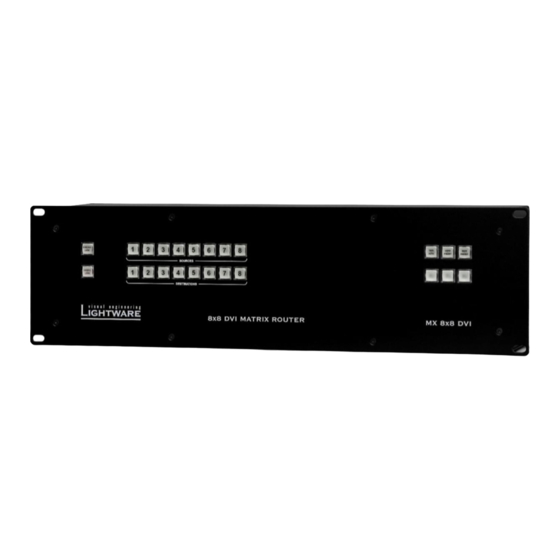
MX8x8DVI-DL User’s Manual Rev. 1.0 2. Controls and connections 2.1. Front panel view Control Lock Source buttons Take / Auto Preset buttons Output Lock Destination buttons Figure 2-1. Front panel view Control Lock Disables or enables front panel operation. When red illuminated, all operations on front panel are prohibited. -
Page 14: Rear View
2.2. Rear view Input connectors Output connectors Serial port Ethernet port AC power connector AC fuse DC voltage indicators CPU live LED port Figure 2-2. Rear view AC power Standard IEC power connector. The router works with 100 to 240 Volts, 50 or 60 Hz power sources. AC fuse Replace with F 3.15 A type only. -
Page 15: Electrical Connections
TMDS wire pair for the clock signal. Dual link signals use three more TMDS wire pairs due to the higher resolution. The extra wires carry the data for every second line of the picture. Those Lightware DVI matrix routers whose model name includes a -DL tag can handle dual link signals. -
Page 16: Dvi Inputs
No output reclocking is provided. Fiber Cable powering As special feature MX8x8DVI / MX8x8DVI-DL, MX6x6DVI / MX6x6DVI-DL is able to supply 500 mA current on DDC +5V output (pin 14 on output connectors) to power fiber optical DVI cables. Standard DVI outputs or VGA cards supply only 55 mA current on +5V output, thus unable to power directly a fiber optical cable. -
Page 17: Rs-232 / Rs-422 Control Port
User’s Manual Rev. 1.0 2.3.4. RS-232 / RS-422 control port Lightware MX8x8DVI / MX8x8DVI-DL, MX6x6DVI / MX6x6DVI-DL can be remote controlled through industry standard 9 pole D-SUB female connector located on the rear panel of the unit. The router can be ordered with RS-232 or RS-422 control port. -
Page 18: Operation
3. Operation 3.1. Power Connect the power cord to the router‟s IEC standard power input connector. The unit is immediately powered ON when the power cord is connected to the AC source. The router does not have a power switch, it remains powered on, until AC line voltage is present. -
Page 19: Viewing Crosspoint State
MX8x8DVI-DL User’s Manual Rev. 1.0 3.2.3. Viewing crosspoint state User can check the current switching status on the front panel using front panel buttons. This status view feature is slightly different in TAKE or AUTOTAKE modes because of different switching philosophy of the two modes. Info Status view occurs whenever the router has to be switched. -
Page 20: Switching
3.2.4. Switching Creating a connection or multiple connections in TAKE mode First press and release the selected source button. The pressed source button and all destination buttons which are currently connected to this source will light up. The dark remaining destination buttons are not connected to this source. -
Page 21: Switching Operations Flowchart
MX8x8DVI-DL User’s Manual Rev. 1.0 3.2.5. Switching operations flowchart To better understand the viewing and switching sequence in TAKE and AUTOTAKE modes, please study the below diagrams. multiple connections can be made by a single TAKE action source viewing select or previewing button source... -
Page 22: Preset Operations
Memory numbers are assigned to source buttons 1 to 8 (MX8x8DVI / MX8x8DVI- DL) or 1 to 6 (MX6x6DVI / MX6x6DVI-DL). The other presets are accessible only through software control (Serial or Ethernet). - Page 23 MX8x8DVI-DL User’s Manual Rev. 1.0 View locked outputs in TAKE mode Step 1. Press and release the Output Lock button. Step 2. The Output Lock button and all the buttons of any locked destinations lights up, and remain illuminated for two seconds. Lock an output in TAKE mode Step 1.
-
Page 24: Remote Operation
If connecting to a computer directly, a cross UTP cable has to be used! User interface comparsion The built-in website and the Lightware matrix controller software have little different capabilities. The table below summarizes the main differences, helping you to select the interface that suits your needs. -
Page 25: Serial Port Settings
User’s Manual Rev. 1.0 3.3.1. Serial port settings MX8x8DVI / MX8x8DVI-DL, MX6x6DVI / MX6x6DVI-DL can be ordered with either RS-232 or RS-422 communication port. The port settings are done in the factory. D-SUB connector pin assignments can be found in chapter 2.3.4... -
Page 26: Software Control - Using Lightware Matrix Controller
4. Software control – Using Lightware Matrix Controller The matrix router unit can be controlled using Lightware Matrix Controller from a Windows PC or Laptop through RS-232 or Ethernet port. 4.1. Installing the Matrix Controller software Step 1. Run Installer_LW_matrix_controller_v3_2_0.exe Step 2. -
Page 27: Establishing The Connection
MX8x8DVI-DL User’s Manual Rev. 1.0 4.2. Establishing the connection The unit can be controlled from a Windows computer using Lightware Matrix Controller software through RS-232 connection or Ethernet port. Step 1. Connect the matrix switcher and the computer via serial port (with standard RS-232 Male to Female cable) ... - Page 28 Step 3. The Find dialog appears automatically If the connection has been made via Ethernet, the software picks the primary Ethernet interface, and shows the available Lightware devices on that port. The device type and the serial number are displayed automatically. Click the desired device, to highlight it.
-
Page 29: Control Menu
MX8x8DVI-DL User’s Manual Rev. 1.0 When the Lightware Matrix Controller finds the hardware, it determines the product type, and the control menu is displayed. The current state of the crosspoint switch is displayed. Figure 4-4. Matrix Controller crosspoint array 4.3. Control menu This menu contains the crosspoint area and the preset area. -
Page 30: Input And Output Card Types
Preset operations can be done on the PRESET panel. The panel can be accessed by clicking on the arrow at the right margin of the software window. Each Lightware matrix switcher has 32 preset memories that can be loaded and saved at any time. -
Page 31: Preset Names
Otherwise, the preset names are stored locally in a file on the computer that was used to save the preset names. (By default this file can be found as C:\Program Files\Lightware\ LW_matrix_controller_v3_2_0\settings.ini) Rename preset Step 1. -
Page 32: Output Parameter Settings
By right clicking on an output label a dialog window appears showing the parameters for the corresponding output. Some settings are only accessible with Lightware PRO series routers. Scope of changes There are two options to apply changes. To set the scope of the changed settings, select the desired option in the top left box. -
Page 33: Edid Menu
MX8x8DVI-DL User’s Manual Rev. 1.0 4.4. EDID menu Advanced EDID Management can be accessed by clicking on the EDID menu. This view is divided in two segments. The upper segment can be opened by clicking the green arrow. This segment contains the EDID editor. The lower segment is the EDID router area. - Page 34 Changing the emulated EDID at one or all inputs Step 1. Select the Emulated EDID List in one of the list window areas in the drop down list. Step 2. Select the desired EDID list in the other list window from which you want to copy (route) the EDID.
-
Page 35: Advanced Edid Editor
4.4.3. Easy EDID Creator Since the above mentioned advanced editor needs more complex knowledge about EDID, Lightware introduced a wizard like interface for fast and easy EDID creation. With Lightware Easy EDID Creator it is possible to create custom EDIDs in four simple steps. -
Page 36: Terminal Menu
4.5. Terminal menu This general-purpose serial terminal is intended mainly for test and debug purposes. After a successful connection is established with a router this terminal can be used either via serial or TCP/IP connection. All commands can be used here that discussed... -
Page 37: Ip Settings
MX8x8DVI-DL User’s Manual Rev. 1.0 4.6.1. IP settings Obtain IP address automatically By selecting the “Obtain IP address automatically” option, the matrix gets the IP address from the DHCP server on the LAN, or if DHCP server is not present, it gets an AutoIP address from the 169.254.xxx.xxx domain. -
Page 38: Find Menu
TCP-serial configuration For informational purposes, the properties of the TCP-serial interface are displayed. This is a communication interface from the embedded Ethernet device towards the main CPU. The “Reset” button resets these values to the factory default, and has a safety purpose only. -
Page 39: Web Control - Using The Built-In Website
5. Web control – Using the built-in website 5.1. Accessing the router’s built-in website Lightware matrices have a built-in web page, which can be accessed over TCP/IP protocol and offers you full control over all settings even if you don‟t have the opportunity to install new programs. -
Page 40: Menu Description
Configuration This page shows the current network configuration of the matrix, such as IP settings and port number. Support The contact information to Lightware Visual Engineering is shown in this page. Page 40 / 75... -
Page 41: Control Menu
5.3.2. Preset operations Preset operations can be done in the right panel of the Control Set and View Crosspoints page. Each Lightware matrix switcher has 32 preset memories that can be loaded and saved any time. Front panel Preset operations effect only the first 8 preset memories, all others from 9 to 32 are available only via the Matrix Controller software or the router‟s... -
Page 42: Output Settings
Step 3. The new I/O configuration is displayed on the matrix switching area. 5.3.3. Output settings Click on Control menu then select Output settings. This menu contains advanced settings for output parameters. Some settings are only accessible with Lightware PRO series routers. Scope of changes The affected output can be selected in the top box, or changes can be applied to all outputs. -
Page 43: Edid Router Operation
MX8x8DVI-DL User’s Manual Rev. 1.0 5.4. EDID Router operation By clicking on the EDID Management menu, the EDID router page appears. When the user enters the menu first, the whole EDID list is being downloaded from the matrix. It may take up to 20 seconds for the first time. After the list is downloaded, the current status of the router‟s EDID is shown in the three boxes. -
Page 44: Learn Edid From Attached Display Device
The user can switch and learn EDIDs also in the Last Attached Monitors EDIDs window. Switching an EDID from this list to an input results dynamic EDID routing. This means that the emulated EDID changes automatically, if a new monitor is attached to the output, by simply copying the data from the monitor. -
Page 45: Network Configuration
MX8x8DVI-DL User’s Manual Rev. 1.0 5.6. Network Configuration The unit's network values are displayed when you select Configuration Network Settings. Info: It is possible to reload factory default IP setup using the front panel buttons. See. 5.6.1. Automatic IP Address Configuration The matrix switcher supports three of the most used automatic IP configuration protocols. -
Page 46: Loading The Default Ip Settings
Step 2. To save, click on Apply Settings button. The new port will be active after the next connection. 5.7. Support For technical support, please don‟t hesitate to contact Lightware Visual Engineering at support@lightware.hu. Page 46 / 75... -
Page 47: About Edid Memory
Info modified. These are the most commonly used resolutions. Info MX8x8DVI (-DL) and MX6x6DVI (-DL) can handle both 128 Byte EDID and 256 Byte extended EDID structures. The attached monitor’s EDID is stored automatically, until a new monitor is Info attached to that particular output. -
Page 48: Programmer's Reference
(except some rare cases, which are uniquely noted). Lightware matrix routers can be controlled with external devices which can communicate according to the router protocol. Lightware routers have a special protocol, but to interoperate with third party devices, a secondary protocol is also provided. -
Page 49: Switching And Control Commands
Description: Viewing all outputs‟ connection results in different response length, because it depends on the router‟s type (length = 8 for MX8x8DVI / MX8x8DVI-DL, length = 6 for MX6x6DVI / MX6x6DVI-DL). The response below supposes a router having 8 outputs. -
Page 50: View Mutes On All Outputs
Description: Viewing all outputs‟ connection results in different response length, because it depends on the router‟s type (length = 8 for MX8x8DVI / MX8x8DVI-DL, length = 6 for MX6x6DVI / MX6x6DVI-DL). The response below supposes a router having 8 outputs. -
Page 51: Lock Specified Output
MX8x8DVI-DL User’s Manual Rev. 1.0 7.3.8. Lock specified output Description: Lock output <out>. Output‟s state cannot be changed until unlocking. Format Example → {#>05} Command {#><out>} Response (1LO<out²>)CrLf ← (1LO05)CrLf Explanation: Output 5 is locked. 7.3.9. Unlock specified output Description: Unlock output <out>. Now output 3 state can be changed. Format Example →... -
Page 52: Preview Preset
7.3.12. Preview preset Description: Preview preset <id> without loading. Format Example (MX8x8) → {VP#3=?} Command {VP#<id>=?} Response (VP#<id>=●<O1>●<O2> ← (VP#3= 02 M02 M01 02 02 01 01 01 ●<O3>●<O4>●<O5>●<O6> )CrLf ●<O7> ●<O8>●)CrLf Legend: Any <Ox> indexes can be a two digit number, or there can be a leading character showing the mute state for the corresponding output. -
Page 53: Query Names Of Presets / Inputs / Outputs
MX8x8DVI-DL User’s Manual Rev. 1.0 7.3.14. Query names of Presets / Inputs / Outputs Description: Each preset / input / output name can be read from the router. Read a preset’s name Format Example → {PNAME#1=?} Command {PNAME#<id>=?} ← (PNAME#1=FIRST PRESET)CrLf Response (PNAME#<id>= <preset_name>)CrLf Explanation: Name for preset 1 is “first preset”. -
Page 54: Reload Factory Default Output Setup
Reload default output names Format Example → {ONAME#3=!} Command {ONAME#<id>=!} ← (ONAME#3=Output 3)CrLf Response (ONAME#<id>= Output<id>)CrLf 7.3.16. Reload factory default output setup Description: Reload factory default output drive currents. Format Example → {r00} Command {r00} ← (APWSE)CrLf Response (APWSE)CrLf 7.3.17. Query IP settings Description: IP setup can be retrieved from the router with this command. -
Page 55: Reload Factory Default Ip Settings
MX8x8DVI-DL User’s Manual Rev. 1.0 7.3.18. Reload factory default IP settings Description: After issuing this command over serial connection the router will reload the factory default IP setup. Format Example → {IP_CONFIG=!} Command {IP_CONFIG=!} ← (Changing IP configuration…)CrLf Response (Changing IP configuration…)CrLf (DONE!)CrLf (DONE!)CrLf... -
Page 56: Router Status Commands
→ {i} Command {i} ← (MX8X8DVI-DL)CrLf Response (<PRODUCT_TYPE>)CrLf Legend: <PRODUCT_TYPE> inputs outputs interface MX6X6DVI-SL single link MX8X8DVI-SL single link MX6X6DVI-DL dual link MX8X8DVI-DL dual link The “-SL” suffix exists only in this response, the product name is without the suffix. -
Page 57: View Installed I/O Cards" Hardware
Command {is} ← (SL# 0 MX-6x6-DVI SCH_1.1 Response (<SL# 0 MB_DESCRIPTOR> )CrLf PCB_1.1)CrLf Explanation 1 (MX6x6DVI router): The router has only one card, with 6 inputs and 6 outputs. All cards are single link DVI-D. Format Example 2 → {is} Command {is} ←... -
Page 58: Edid Router Commands
7.5.2. Route EDID to the selected input (dynamic) Description: Copies EDID from location <loc> to input <in>. Location <loc> should be 101...108 (MX8x8DVI, MX8x8DVI-DL) or 101...106 (MX6x6DVI, MX6x6DVI-DL) as opposed to static routing where <loc> should be between 1..100. Format Example →... -
Page 59: Save Edid From Output To Memory Location (Learn Edid)
MX8x8DVI-DL User’s Manual Rev. 1.0 Explanation: Factory preset EDID from memory location 48 is emulated on inputs 1 and 2. User saved EDID from memory location 53 is emulated on input 3. EDID from output 1 is dynamically emulated on inputs 5, 6, 7, and 8. 7.5.5. -
Page 60: Download Edid Content From The Router
7.5.8. Download EDID content from the router Description: EDID hex bytes can be read directly. The router will issue the whole content of the EDID present on memory location <loc> (256 bytes). Format Example → {we1>} Command {we<loc>} Response (EB#<loc>●<B1> ←... -
Page 61: Router Initiated Commands
MX8x8DVI-DL User’s Manual Rev. 1.0 7.6. Router initiated commands 7.6.1. EDID status changed Description: This is sent after all commands which changes the EDID (EDID copy, EDID switch), or after a new EDID source ie. a new display device is connected to the router. -
Page 62: Commands - Quick Summary
7.7. Commands – Quick summary Control commands See in Command description Command chapter Switch one input to one output 7.3.1 {<in>@<out>} Switch one input to all outputs 7.3.2 {<in>@O} View connection on the specified output 7.3.3 {?<out>} View connection on all outputs 7.3.4 {VC} View mutes on all outputs... -
Page 63: Firmware Upgrade
{WL#<loc>} 8. Firmware upgrade Using Lightware bootloader application to upgrade router’s firmware The matrix router can only be upgraded via LAN, so connect the matrix router to the local subnet. Be sure that there is no other active connection with the router via Ethernet. - Page 64 If the bootloader finds one or more routers their IP addresses will be listed in the tree view window. On the tree view, device type and serial number is shown after the IP address. Info Note, that you must wait until all the devices on the network completely start up, before pressing FIND button.
- Page 65 MX8x8DVI-DL User’s Manual Rev. 1.0 After the connection is made, the device properties, and the installed hardware parts are displayed. Select the controller(s) that need(s) new firmware by clicking the checkbox next to MX-DVI-CPU is the main processor‟s firmware. MX-CP1 is the firmware for the front panel.
- Page 66 When the reprogramming is finished, a “Done!” message will appear in the bottom left corner. The application closes the connection, and the router restarts. Step 8. Done! If the upgrade was successful, the following window pops up: Now you can close the application, or you can select another matrix router to upgrade.
-
Page 67: Troubleshooting
MX8x8DVI-DL User’s Manual Rev. 1.0 9. Troubleshooting 9.1. General problems Check the router Check whether the router is properly powered and whether CPU LIVE LED is blinking. Try performing a reset through the controller software, or unplug and reconnect the router‟s power cable. 9.2. -
Page 68: Picture Is Not Displayed Or Distorted
Check the protocol Check whether the proper protocol is selected (see section about Changing and viewing protocols on page 48). Select Protocol #1 in order to use the matrix with the controller software. Check alive connections Only one connection is allowed simultaneously. Check whether there is another open connection (e.g. -
Page 69: Specifications
MX8x8DVI-DL User’s Manual Rev. 1.0 10. Specifications General Power ............... 100-240 V AC 50/60 Hz 3 A Compliance ..................CE, UL, FCC EMI/EMC ..............EN 55103-1, EN 55103-2 Safety ..................EN 60065 Class I Warranty ....................3 years Enclosure Rack mountable ................Yes, 3U high Material .................... - Page 70 Vertical Horizontal Pixel Clock Resolution Comment frequency (Hz) frequency (KHz) frequency (MHz) 640x480 60.00 31.47 25.18 DOS VGA 800x600 60.32 37.88 VESA SVGA 800x600 75.00 46.87 49.5 VESA SVGA 832x624 74.55 49.72 57.29 MACINTOSH 1280x720 60.00 45.00 74,25 HDTV 720p 1024x768 VESA XGA 60.00...
-
Page 71: Mechanical Drawings
MX8x8DVI-DL User’s Manual Rev. 1.0 10.1. Mechanical Drawings Front View 133 mm 482 mm Rear View 446 mm Top View 102 mm 108.4 mm housing only including buttons and connectors Page 71 / 75... - Page 72 Side View 133 mm 131 mm VENTILLATION HOLES VENTILLATION HOLES Never block air flow! Never block air flow! 2 mm 2 mm 102 mm 102 mm 108.4 mm 108.4 mm Page 72 / 75...
-
Page 73: Version Applicability
The customer shall pay shipping charges when unit is returned for repair. Lightware will cover shipping charges for return shipments to customers. In case of defect please call your local representative, or Lightware at Lightware Visual Engineering 1071. Budapest Peterdy str. 15, HUNGARY Tel.:... -
Page 74: Quality Check Record
13. Quality Check Record Model name Serial number Date of manufacture Checked Hardware Module Hardware Firmware Mother board EDID management LAN control server WEB content MAC address Control Panel Electrical check GND/EARTH Safety Inputs +3.3V; +5V Outputs CPU Live RS-232 Buttons Page 74 / 75... -
Page 75: Document Revision History
MX8x8DVI-DL User’s Manual Rev. 1.0 14. Document revision history Document Release Date Changes Checked by Rev. 1.0 02-06-2010 released Tamas Lehel Rev. 0.8b 19-04-2010 first beta edition Tamas Lehel Page 75 / 75...
Need help?
Do you have a question about the MX6x6DVI and is the answer not in the manual?
Questions and answers