Breas Vivo 3 Clinician Manual
Hide thumbs
Also See for Vivo 3:
- User manual (137 pages) ,
- User manual (113 pages) ,
- User manual (81 pages)
Table of Contents
Advertisement
Quick Links
Advertisement
Table of Contents

Related Manuals for Breas Vivo 3


Summary of Contents for Breas Vivo 3
- Page 1 Vivo 3 Clinician’s Manual DOC. 007232 EN-EU Y-2 2019-09-03...
-
Page 3: Table Of Contents
Table of Contents Introduction........................9 Manufacturer Information.................. 10 What is the Vivo 3? ................... 10 1.2.1 Non Invasive Interfaces ..............11 1.2.2 Mobility and Usage Environment ............11 1.2.3 Continuous Operation................11 1.2.4 Service Life ..................11 Intended Use......................11 Intended Users....................11 1.4.1 Respiratory health care specialists ............11 1.4.2... - Page 4 4.2.21 Heated Circuit Level................62 Prepare the Vivo 3 for Use ....................63 Checking the Vivo 3 before First Use ............... 63 Placing the Vivo 3....................63 Connecting the Vivo 3 to Power Supply............64 Connecting the Patient Circuit ................65 5.4.1...
- Page 5 Using the Lightweight Mobility Bag........... 85 6.7.9 Using the Y-Cable ................86 6.7.10 Using the Vivo 3 with the Trolley............86 Transfer Data between the Vivo 3 and a PC............. 87 6.8.1 Log Data.................... 88 6.8.2 Transfer Data using a Memory Card..........88 6.8.3...
- Page 6 High Patient Air Temp. (High Patient Air Temperature) ....107 7.4.9 Flow Sensor Failure ................ 107 7.4.10 Internal Function Failure ..............108 Cleaning and Maintenance ................... 109 Cleaning the Vivo 3 ..................109 8.1.1 Clean the Main Unit Externally ............109 8.1.2 Air Pathway Disinfection ..............110 8.1.3 Clean the Patient Circuit ..............110...
- Page 7 9.7.3 Recommended separation distances between portable and mobile RF communications equipment and the Vivo 3 ....127 9.7.4 Recommended separation distances between external power conductors and the Vivo 3 .............. 128 Delivery Settings ..................... 128 Accessories ........................130 10.1 Accessories/Consumables ................130 10.2...
-
Page 9: Introduction
CAUTION! Read this Clinician’s manual thoroughly so that you completely understand how the Vivo 3 is operated and maintained before taking it into use, to ensure correct usage, maximum performance and serviceability. Non-professional caregivers (e.g. family members) should consult the medical equip- ment provider’s respiratory therapist if they have any questions about the function,... -
Page 10: Manufacturer Information
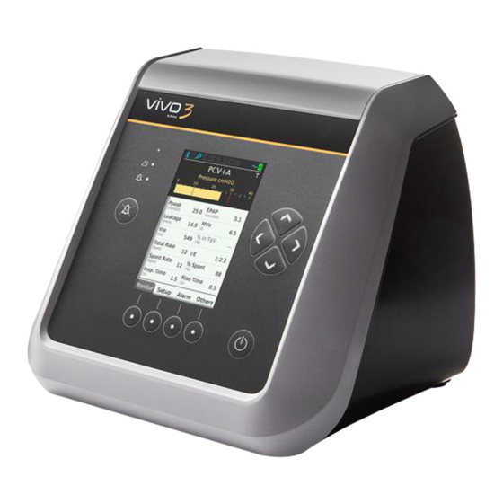
What is the Vivo 3? The Vivo 3 is an internally powered pressure ventilator capable of delivering invasive or non-invasive ventilatory support for the care of individuals who require long-term sup- port from mechanical ventilation for respiratory insufficiency or respiratory failure, with or without obstructive sleep apnea. -
Page 11: Non Invasive Interfaces
1.2.4 Service Life The expected service life of the Vivo 3 is 5 years or 20,000 hours. Intended Use Vivo 3 is intended to provide non-invasive or invasive ventilation for patients weighing over 10 kg (22 lbs) who require long-term support or mechanical ventilation for respira- tory insufficiency or respiratory failure, with or without obstructive sleep apnea. -
Page 12: Lay Operators
The User Manual contains the information intended for patients and lay operators. Training The lay operator shall be trained to basic knowledge of the Vivo 3 and in the specific operations they are assigned to perform. The training shall be based on the user manual and the responsible clinical personnel shall assess the level of training required for each lay operator. -
Page 13: Contraindications
Training and Certification Service personnel shall be trained on the Vivo 3 and certified by Breas for being allowed to perform any service, repairs or other operations on the Vivo 3. The training consists of reading the services manual in complete. After completed training the certification test may be performed. -
Page 14: About This Manual
Patients should report any unusual chest pain, severe headache or increased breathlessness. The following side effects may occur during the course of therapy with the Vivo 3, patients are advised to report any new or changing adverse effects to their physician: •... - Page 15 Risk of equipment damage, loss of data, extra work, or unexpected results. Note Information that may be valuable but is not of critical importance, tips. Reference Reference to other manuals with additional information on a specific topic. Introduction 15 Doc. 007232 Y-2 Vivo 3 Clinician’s Manual...
-
Page 16: Safety Information
Risk of Insufficient Ventilation Usage outside the specified operating conditions may cause reduced performance. The Vivo 3 must only be used in accordance with the operating conditions specified in this operating manual Risk of Faulty Treatment Do not use the Vivo 3 in the event of •... - Page 17 Always prepare the Vivo 3 as described in this manual before use. Risk of Unnoticed Critical Conditions • All the physiological alarms of the Vivo 3 must be set at safe levels that will effec- tively warn the user of any risk.
- Page 18 Make sure to place and pack the device in a way that prevents unintentional start of the machine. Due to the internal battery, the Vivo 3 may start if the Start/Stop button is pressed even without the mains being connected.
-
Page 19: Electricity - Warnings And Precautions
High voltage contact may cause cardiac arrhythmia. • Do not operate the Vivo 3 if it has a damaged power cord, power supply or casing. • To avoid electrical shock, only clean the Vivo 3 according to instructions in this manual. -
Page 20: Electromagnetic Compatibility And Electrostatic Discharge (Emc And Esd)
Vivo 3. Please note some of these RF emitters may not be visible and the Vivo 3 can poten- tially be exposed to fields from these RF emitters without the user’s awareness. If abnormal performance of the Vivo 3 is observed, and the RF emitters cannot be identified and removed, the Vivo 3 may need to be reoriented or relocated. -
Page 21: Disposal
Do not use or store the Vivo 3 in a magnetic resonance (MR) environment. Use of the Vivo 3 in an MR environment may result in malfunction of the Vivo 3 and pose unacceptable risk to the patient, medical staff or other persons. -
Page 22: Patient Circuit - Warnings And Precautions
• For active exhalation valve circuits: Check the function of the exhalation valve and that is not blocked or obstructed. • The Vivo 3 should be turned on and the function of the leakage port should be checked before use: The pressurized air from the Vivo 3 causes a continuous flow of air through the leakage port, enabling flushing of exhaled air. - Page 23 When present, remove the moisture. Before attempting to dry the circuit, disconnect it from the Vivo 3 to ensure no water flows back into the Vivo 3. The frequency at which these checks must be performed will depend on the patient’s condition and the device used.
-
Page 24: Filter Usage - Warnings And Precautions
WARNING! Risk of Cross-Contamination Patient circuits might get contaminated by exhaled gases. To avoid cross-contamina- tion, always use a properly cleaned or a new patient circuit when the Vivo 3 is to be used by a new patient. NOTE For masks and accessories, always follow the manufacturer’s instructions. -
Page 25: Invasive Use - Warnings And Precautions
Risk of Rebreathing The Vivo 3 is equipped with a low leakage alarm. The low leakage alarm is not a sub- stitute for operator vigilance in ensuring that the leakage ports remains clear at all times. -
Page 26: Humidification And Heating - Warnings And Precautions
The Vivo 3 is equipped with a low leakage alarm. However, the alarm is not a substi- tute for operator vigilance for ensuring that the leakage ports remains clear at all times. -
Page 27: Cleaning And Maintenance - Warning And Precautions
Cleaning and Maintenance — Warning and Precautions This manual contains instructions for cleaning and maintenance that can be carried out by the care provider or users with physical ability and working knowledge of the system. Safety Information 27 Doc. 007232 Y-2 Vivo 3 Clinician’s Manual... -
Page 28: Oxygen Usage - Warning And Precautions
Risk of Electric Shock Cleaning with excessive water or opening the device’s casing without certified training may cause electric shocks. The Vivo 3 should be regularly cleaned and maintained in accordance with this oper- ating manual. Risk of Electric Shock High voltage contact may cause cardiac arrhythmia. - Page 29 The presence of oxygen can speed up combustion of inflammable materials. Risk of Fire When oxygen is used with the Vivo 3, the oxygen flow must be turned off when the Vivo 3 is not operating. Oxygen delivered into the patient tubing may accumulate within the machine enclosure.
-
Page 30: Mobile Use - Warning And Precautions
• 80% oxygen concentration: -7.5% deviation 2.10 Mobile Use — Warning and Precautions This section applies if using the Vivo 3 during transit, for example on a wheel chair or in a car. No Attachable Humidifier During Mobile Use WARNING! Risk of Suffocation Do not use the attachable humidifier during mobile use. - Page 31 CAUTION! During mobile use, protect the device with either of the Protective Cover accessory or the Lightweight Mobility Bag accessory. Do not use the Vivo 3 while in a carry bag. Safety Information 31 Doc. 007232 Y-2 Vivo 3 Clinician’s Manual...
-
Page 32: Product Description
Product Description This section describes the main Vivo 3 medical electric equipment. For information about accessories and user replaceable spare parts., see .10 Accessories, page 130. Main Components Part Function Breas Part no. Ventilator unit Main unit. 229000 006994 Power supply adapter for the... -
Page 33: Ventilator Front
Clinician’s manual: 007232 Carry bag For transportation, when not 007013 in use. Patient circuit, 15 mm Delivers air to the patient 006712 Ventilator Front This section describes the front panel. Product Description 33 Doc. 007232 Y-2 Vivo 3 Clinician’s Manual... - Page 34 Audio pause button Pauses the alarm sound. Audio Pause LED Lights yellow when the alarm sound is paused. Alarm LED Flashes during active alarms. 34 Product Description Vivo 3 Clinician’s Manual Doc. 007232 Y-2...
-
Page 35: Ventilator Back
Ventilator Back Item Description Power port Port for connecting the power sup- ply. See 5.3 Connecting the Vivo 3 to Power Supply, page 64 Oxygen port Connection for low pressure/bleed- in oxygen Patient air outlet Connection for patient circuit Patient air inlet... -
Page 36: Power Management
Power supply Y—cable is required. If a power source fails, the Vivo 3 will switch to the next source in priority and show a message on the display. If all available sources fail, the Power Failure alarm is given and the Vivo 3 shuts down. -
Page 37: Menus
Charging Preparing the Battery for Storage If storing the Vivo 3, longer than 1 month, make sure that the internal battery is about half charged before storing, in order to maintain maximum battery capacity. Optimal storage temperature is 5 to 30°C (41 to 86°F). - Page 38 Press the navigation button for the requested function page. ⇒The page is now displayed. 2 For functions with several pages grouped together, press the naviga- tion button again to browse the pages. 38 Product Description Vivo 3 Clinician’s Manual Doc. 007232 Y-2...
- Page 39 3 Leave the sub page using the left arrow button Change a Setting Select the setting (indicated by an arrow to the right of the item text) using the Up or Down arrow button. Product Description 39 Doc. 007232 Y-2 Vivo 3 Clinician’s Manual...
-
Page 40: The Monitor Page
3.5.2 The Monitor Page The monitor page displays the treatment data. It consists of a bar graph illustrating the current pressure and text area displaying current monitored values in text. 40 Product Description Vivo 3 Clinician’s Manual Doc. 007232 Y-2... -
Page 41: The Setup
2. Low pressure alarm level 3. Set inspiration pressure level 4. High pressure alarm level For information about monitored values, see 6.6.1 Treatment Values Monitored by the Vivo 3, page 72. 3.5.3 The Setup Pages The setup pages contain settings related to the treatment. -
Page 42: The Alarm
The available languages are listed with their native names accompanied by a flag representing a country where the lan- guage is spoken. Default value: English (The language selection menu is displayed when the Vivo 3 is started for the first time.) Pressure Unit Value range: • cmH •... - Page 43 3.5.5.4 Device Memory Command Description Save Memory Data on Copies the memory data from the internal memory to the Card memory card. Erase Memory Data Erases memory data from the internal memory Product Description 43 Doc. 007232 Y-2 Vivo 3 Clinician’s Manual...
- Page 44 • Usage log (containing at least 1 year data of non-clinical events, alarms and settings) 3.5.5.5 Clock Setting Description Time Sets the time for the Vivo 3. The time is used for logs and reports. Date Sets the date for the Vivo 3. The date is used for logs and reports.
- Page 45 Patient Operating Time Total hours of usage Reset Patient Operating Reset the counter to 0. Time 3.5.5.9 About Setting / information Description Regulatory FCC Contains FCC Compliance statement Regulatory IC Contains IC Statment Product Description 45 Doc. 007232 Y-2 Vivo 3 Clinician’s Manual...
-
Page 46: Symbols On The Vivo 3
Symbols on the Vivo 3 Symbols on the Product Information Label Symbol Description Manufacturer information Nemko certifikation mark (NRTL/SCC accredited) Degree of protection provided by enclosure. See 9.3 Environmental Conditions, page 117 for explanation. (Symbol only applicable in U.S.) Caution: U.S. Federal law restricts this device to sale by or on the order of a licensed healthcare practitioner. - Page 47 Symbol Description Serial number Date of manufacture Symbols on the Vivo 3 Back Symbol Description Oxygen connection port. Max 30 l/min and 100 kPa. Power connection port. Use approved power supplies only. USB port SD memory card port I/O port for accessory box/SpO Product Description 47 Doc.
- Page 48 Additional Symbols on Parts and Accessories This section describes additional symbols for Vivo 3 detachable parts and accessories from Breas Medical. Each item, or its package, have the symbols that applies for the specific accessory. Symbol Description Caution, hot surface Caution symbol, read the Accessory’s instructions for more...
- Page 49 Symbol Description Effort belt port (not used) AC power port DC power port port Product Description 49 Doc. 007232 Y-2 Vivo 3 Clinician’s Manual...
-
Page 50: Symbols On The Display
8. All alarms shut off 9. Powered by mains. 10. Powered by external battery (no icon = powered by internal battery) 11. Battery status (red — yellow — green). A flash indicates charging. 50 Product Description Vivo 3 Clinician’s Manual Doc. 007232 Y-2... -
Page 51: Treatment Functions And Settings
Vivo 3. Lay operators must only use the User Manual, not the Clinician’s Manual. Treatment Modes This section describes the ventilating modes of the Vivo 3. 4.1.1 PCV+A — Pressure Controlled Ventilation (Assisted) In PCV+A mode, the ventilation is controlled by set values for pressure, inspiratory time, and rise time. -
Page 52: S - Spontaneous
The inspiration starts by the interval set by the breath rate. The inspiration stops and the expiration starts by either of the following triggers: • The inspiration time expires. • The High Pressure Alarm limit is reached. 52 Treatment Functions and Settings Vivo 3 Clinician’s Manual Doc. 007232 Y-2... -
Page 53: Cpap - Continuous Positive Airway Pressure
4.1.6 CPAP — Continuous Positive Airway Pressure In CPAP mode the Vivo 3 is applying a continuous positive pressure to the airways. The flow will automatically be adjusted to maintain the set CPAP level. Treatment Settings This section describes settings and parameters that affects the ventilating function of the Vivo 3. -
Page 54: Expiratory Positive Airway Pressure (Epap)
4 cmH O to 20 cmH Default value 10 cmH Setting resolution Below 10 cmH O: 0.5 cmH Above 10 cmH O: 1.0 cmH Available in modes CPAP 54 Treatment Functions and Settings Vivo 3 Clinician’s Manual Doc. 007232 Y-2... -
Page 55: Breath Rate
4.2.5 Breath Rate The Breath Rate setting defines the minimum number of breaths the Vivo 3 will deliver as long as no inspiratory trigger effort from the patient is detected. The cycles will be ventilator-initiated breaths. Property Description Value range... -
Page 56: Maximum Inspiratory Time (Max. Insp. Time)
The Assisted breath modes in PCV are turned off if the inspiratory trigger is set to Off. Property Description Value range Auto, 1 to 9 Default value Auto 56 Treatment Functions and Settings Vivo 3 Clinician’s Manual Doc. 007232 Y-2... -
Page 57: Expiratory Trigger (Exp.trigger)
A high setting will give a slow increase and therefore a shorter plateau. Property Description Value range Auto, 1 to 9 Default value Auto Setting resolution Available in modes • PCV+A • PSV • S • S/T • T Treatment Functions and Settings 57 Doc. 007232 Y-2 Vivo 3 Clinician’s Manual... -
Page 58: 4.2.12 Target Volume
4.2.12 Target Volume The Target Volume setting defines the tidal volume that the Vivo 3 will aim for while ventilating the patient in a pressure mode. This is done by adapting the Inspiratory Pres- sure between two adjustable pressure limits: Min IPAP and Max IPAP. -
Page 59: 4.2.14 Min Pressure
The Min pressure setting is only used when Target Volume is activated. Min pressure defines the lower pressure limit down to where the Vivo 3 can decrease the pressure to maintain the set Target Volume. If the actual volume is above Target Volume at Min pressure, the Vivo 3 will continue to ventilate at this Min pressure setting. -
Page 60: 4.2.16 Ramp Down
O to the set value for CPAP (CPAP mode) Default value • The set value for EPAP (PSV and PCV+A modes) • The set value for CPAP (CPAP mode) 60 Treatment Functions and Settings Vivo 3 Clinician’s Manual Doc. 007232 Y-2... -
Page 61: 4.2.18 Humidifier
• CPAP 4.2.18 Humidifier This setting defines whether a humidifier shall be used. By default, this setting can be modified in Clinical mode only, but the Vivo 3 may be configured to allow modification in home mode as well. WARNING! Read the section 2.7 Humidification and Heating —... -
Page 62: 4.2.20 Heated Circuit
This setting defines whether a heated patient circuit shall be used as patient circuit. By default, this setting can be modified in Clinical mode only, but the Vivo 3 may be configured to allow modification in home mode as well. -
Page 63: Prepare The Vivo 3 For Use
Ensure that you have the equipment mentioned in 3.1 Main Components, page 32 2 Ensure that the equipment is in good condition. 3 If stored more than 1 month, connect the Vivo 3 to the power supply to recharge the internal battery. -
Page 64: Connecting The Vivo 3 To Power Supply
Vivo 3, such as a curtain etc. Connecting the Vivo 3 to Power Supply This chapter describes how to connect a Breas power supply. WARNING! Read the chapter 2.2 Electricity — Warnings and Precautions, page 19 carefully to make sure all conditions are considered and met. -
Page 65: Connecting The Patient Circuit
Read the chapter 2.4 Patient Circuit — Warnings and Precautions, page 22 Carefully to make sure all conditions are considered and met. The Vivo 3 is intended to be used with leakage circuits only. Recommended leak rate: 20 to 50 liters per minute at 10 cmH Prepare the Vivo 3 for Use 65 Doc. -
Page 66: Connect The Heated Patient Circuit
Power up the Vivo 3 This function check may be performed as a pre-use check or whenever the function of the Vivo 3 needs to be checked. 66 Prepare the Vivo 3 for Use Vivo 3 Clinician’s Manual... -
Page 67: Adjusting The Settings
• The audio pause LED lights yellow. • In about a second, both LEDs are turned off. If the test fails, do not use the Vivo 3. Contact your supplier of the Vivo 3 for a technical check. 3 Perform a pre-use test (select Others —> Pre-use Test). - Page 68 5 Make a copy of the Patient Settings Record on page 138 and document the settings. The Vivo 3 is now ready for use. If restarting the Vivo 3, it will start with the settings used when it was powered off.
-
Page 69: How To Use The Vivo 3
The therapy settings shall be based on a physician’s description. Changes to settings must be made by authorized clinical personnel only. Make sure that the Vivo 3 is in Standby mode. How to Use the Vivo 3 69 Doc. 007232 Y-2... -
Page 70: Stop The Treatment
• In about a second, both LEDs are turned off If the function test beep absents, take the Vivo 3 out of use and contact your supplier of the Vivo 3 e. Stop the Treatment Press and hold the On/Off button until the Stopping Treatment progress bar is filled. -
Page 71: Switch Off The Vivo 3
Ramp Down time has been specified.) Switch Off the Vivo 3 Make sure that the treatment is stopped and the Vivo 3 is in Standby mode. 2 Press the On/Off button. ⇒When the message “Do you want to turn off the ventilator?” is dis-... -
Page 72: Treatment Values Monitored By The Vivo 3
The monitor page displays treatment data monitored by the Vivo 3. It consists of a bar graph illustrating the current pressure and text area displaying monitored values in text. Bar graph legend 1. Current pressure 2. Low pressure alarm level 3. -
Page 73: Treatment Values Monitored By External Equipment
The device shall comply with ISO 80601-2-55 and have a high oxygen level alarm. Using Accessories This section describes how to use accessories provided by Breas Medical. How to Use the Vivo 3 73 Doc. 007232 Y-2... -
Page 74: Using The Attachable Humidifier
Using the Attachable Humidifier WARNING! Read the section 2.7 Humidification and Heating — Warnings and Precautions, page 26 before using the Vivo 3 with the attachable humidifier. WARNING! Risk of Burns If you remove and open the humidifier just after using the ventilator, ensure that you don’t touch the heater inside the humidifier since it can be very hot. - Page 75 2 Fill the humidifier with water. 3 Insert the humidifier. Detach the Humidifier from the Vivo 3 If any treatment is running, stop it. 2 Push down the locking latch (a) and then pull the humidifier out.
- Page 76 3 If you will use the Vivo 3 without the humidifier, install the air bypass unit in place of the humidifier. Fill the Humidifier Duration of operation between humidifier refills Humidifier level (5): 12 hours. At lower settings, the duration will be longer.
- Page 77 (a) and then pulling it out. 3 Make sure the humidifier is correctly filled and push it into the Vivo 3 so the locking latch is engaged. ⇒A click indicates that the humidifier is correctly installed.
- Page 78 If you remove and open the humidifier just after using the ventilator, ensure that you don’t touch the heater inside the humidifier since it can be very hot. 78 How to Use the Vivo 3 Vivo 3 Clinician’s Manual Doc. 007232 Y-2...
-
Page 79: Using The Heated Circuit
Using the Heated Circuit WARNING! Read section 2.7 Humidification and Heating — Warnings and Precautions, page 26 before using the Vivo 3 with the heated circuit. NOTE The heated circuit requires connection to the Mains power supply to work. Information about safety, warnings, product description, installation, usage, cleaning, maintenance and technical specifications can be found in the user instruction for the heated circuit. -
Page 80: Using The Spo Sensor
The SpO module (consisting of a SpO sensor, an electronic unit) is intended to meas- ure functional oxygen saturation of arterial hemoglobin (SpO2) and pulse rate. 80 How to Use the Vivo 3 Vivo 3 Clinician’s Manual Doc. 007232 Y-2... - Page 81 The SpO module can be connected to the Vivo 3 (item 1 above) using the SpO adapter cable (007079) or to the accessory box (007000) in order to monitor and store measurements. The SpO measurements will be stored in the data memory which can be downloaded to a PC and viewed in the PC software.
-
Page 82: Using The Oxygen Supply Adapter
CAUTION! • When using the Vivo 3 with the SpO2 sensor, the Vivo 3 displays functional oxygen saturation measured by the sensor. • The following information concerns the light emitted by the SpO2 – Peak Wavelength (red): 660 nm – Peak Wavelength (infrared): 905 nm –... -
Page 83: Using The Nurse Call Connection
Connect the Oxygen supply Connect the oxygen adapter (article no. 005032) to the oxygen supply’s tube. 2 Connect the oxygen adapter to the oxygen port at the back of the Vivo 3. See 3.3 Ventilator Back , page 35 for detailed information. -
Page 84: Using The Remote Alarm Unit
⇒The Nurse call symbol is now lit on the display. 3 Trigger an alarm on the Vivo 3 and check that it activates the nurse call system. For detailed information about triggering alarms, see 8.4 Alarm Tests, page 112. 6.7.6... -
Page 85: Using The Protective Cover
3 Start the remote alarm unit. 4 Trigger an alarm on the Vivo 3 and check that it activates the remote alarm system. For detailed information about triggering alarms, see 8.4 Alarm Tests, page 112. 6.7.7 Using the Protective Cover The protective cover is intended for mobile use of the Vivo 3 in hospitals, institutions and home care environments. -
Page 86: Using The Y-Cable
6.7.9 Using the Y-Cable The Y-cable is used for connecting the Vivo 3 to both mains and external DC at the same time. see 5.3 Connecting the Vivo 3 to Power Supply, page 64. When both power sour- ces are available, the mains will be used. -
Page 87: Transfer Data Between The Vivo 3 And A Pc
Read the section 2.2 Electricity — Warnings and Precautions, page 19. CAUTION! Do not eject the memory card or disconnect the USB cable while the Vivo 3 is trans- ferring data. Doing so may result in loss of data and/or damaged equipment. -
Page 88: Log Data
The logs can be viewed in a PC with the Vivo PC Software installed. 4 Remove the memory card from the Vivo 3 and insert it to a memory card reader connected to a PC with the Vivo PC Software installed. -
Page 89: Transfer Data Using An Usb Cable
If the air is dry despite using the humidi- fier, increase the level of humidification. If the humidifier doesn’t deliver any heat, check that the Vivo 3 is powered from the AC power supply; the humidifier doesn’t work on battery. -
Page 90: Alarms
WARNING! Risk of Unnoticed Critical Conditions • All the physiological alarms of the Vivo 3 must be set at safe levels that will effec- tively warn the user of any risk. The alarm levels should be assessed considering the patient’s treatment settings. -
Page 91: Operator's Position
Handle Alarms 7.2.1 Identify an Alarm Condition If an alarm condition is detected, the Vivo 3 main unit and the remote alarm unit (if connected) will alarm without delay. The alarms will remain active until the alarm condi- tion is resolved. - Page 92 A “>>” symbol indicates that more alarms are to be displayed in the loop. Alarm LED signal • High priority alarms Red light, flashing quickly (0.5 s. interval). • Medium priority alarms Yellow light, flashing slowly (2 s. interval). 92 Alarms Vivo 3 Clinician’s Manual Doc. 007232 Y-2...
-
Page 93: Pause The Alarm Sound
To reset an alarm, correct the cause of the alarm condition. ⇒Once the cause is corrected, the alarm disappears from the display. WARNING! If an alarm condition cannot be corrected, take the Vivo 3 out of use and contact your supplier of the Vivo 3 e. 7.2.4 View Historical Alarms To view historical alarms, press the Alarm button three times. -
Page 94: Adjust The Alarm Sound Level
2 Press the Down or Up arrow but- ton to select the Alarm Sound Level setting. 3 Press the Left or Right arrow but- tons to adjust the sound level. 94 Alarms Vivo 3 Clinician’s Manual Doc. 007232 Y-2... -
Page 95: Physiological Alarms
A full breath is performed with maximum pressure below the alarm limit. Ventilator action The Vivo 3 will continue treatment according to the current settings. The actual breath is however terminated if the High Pressure alarm limit is reached. Setting range •... -
Page 96: Low Pressure Alarm
Alarm text Priority High Alarm condition A Low Pressure alarm will be given when the Vivo 3 pressure fails to reach the low pressure alarm limit for 15 seconds. Possible cause • Disconnection of patient circuit. • Mismatch between pressure setting and alarm setting. -
Page 97: High Breath Rate Alarm
• Too sensitive setting of the inspiratory trigger setting. Reset criteria The breath rate goes below the alarm limit. Ventilator action The Vivo 3 will continue treatment according to the current settings. Setting range • 10 bpm to 50 bpm •... -
Page 98: High Minute Volume Alarm
• Increased breath rate. Reset criteria The minute volume goes below the alarm limit. Ventilator action The Vivo 3 will continue treatment according to the current settings. Setting range • 1 l. to 40 l. • Off Setting resolution 0.5 l. -
Page 99: Rebreathing Alarm
Possible cause • Obstructed or occluded patient circuit. • Incorrect patient circuit. Reset criteria The leakage is back within limits. Ventilator action The Vivo 3 will continue treatment according to the current settings. Setting range • On • Off 7.3.8... -
Page 100: Disconnection Alarm
• The patient has removed the mask. • Circuit disconnection. • Pilot pressure tube disconnection Reset criteria The leakage is back within limits. Ventilator action The Vivo 3 will continue treatment according to the current settings Setting range • On • Off 100 Alarms Vivo 3 Clinician’s Manual... -
Page 101: 7.3.10 High Epap Alarm
• Changes in airway resistance and or compliance. Reset criteria EPAP has gone below the alarm limit (lower than 30% above the set value). Ventilator action The Vivo 3 will continue treatment according to the current settings. Setting range • On • Off 7.3.11... -
Page 102: High Spo 2 Alarm
Too high flow of bleed-in oxygen. Reset criteria The SpO value goes back below the alarm limit. Ventilator action The Vivo 3 will continue treatment according to the current settings. Setting range • 80 % to 100 % • 90 % to 100 % •... -
Page 103: 7.3.14 High Pulse Rate Alarm
• Bad positioning of the finger probe. Reset criteria The pulse rate goes back below the alarm limit. Ventilator action The Vivo 3 will continue treatment according to the current settings. Setting range 20 to 250 bpm (beats per minute) -
Page 104: Technical Alarms
External power supply connected to ventilator. Ventilator action The Vivo 3 stops the treatment, turns off the display and gives the Power Fail alarm for at least 2 minutes. If power is restored within the alarm time, the ventilator will automatically resume treatment with current settings. -
Page 105: Spo 2 Artifact
Reset criteria Normal communication with the sensor is reestablished. An information message remains until acknowledged by the user. Ventilator action The Vivo 3 will continue treatment according to the current settings. 7.4.4 Artifact This alarm requires a connected SpO sensor. -
Page 106: Ambient Pressure Compensation Lost Alarm
Ventilator action The Vivo 3 will continue treatment according to the current settings. Normal atmospheric pressure at sea level will be used as approximation for the temporary ambient pressure compen- sation. -
Page 107: High Patient Air Temp. (High Patient Air Temperature)
Correct data from the sensor is received again. An information message remains until acknowledged by the user. Ventilator action The Vivo 3 will continue treatment but with the following limitations: • Monitoring of leakage is disabled. • Volume measurements are disabled. -
Page 108: 7.4.10 Internal Function Failure
The ventilator will stop the treatment. Action to take Restart the Vivo 3. If the alarm persists or reoccurs: Take a note of the error code and contact your supplier of the Vivo 3 . 108 Alarms Vivo 3 Clinician’s Manual Doc. 007232 Y-2... -
Page 109: Cleaning And Maintenance
4 Clean the outside of the Vivo 3 using a lint free cloth moistened with a mild soap solution and / or ethanol 70%. 5 When the equipment is clean and dry, reconnect the patient circuit and any accesso- ries that was disconnected during the cleaning. -
Page 110: Air Pathway Disinfection
Clean and Replace Patient Air Inlet Filters The Vivo 3 patient air inlet filters are located inside a magnetic filter holder at the back of the ventilator. The table below describes the filters and their minimum maintenance intervals. - Page 111 • Replace: every 4th week or when assigning the Vivo 3 to a new patient. * If the Vivo 3 is used in an environment with high grades of pollen or pollutions, shorter intervals might be required. Turn off the Vivo 3 and place it on a clean dust free surface.
-
Page 112: Change Of Patients
Change of Patients If assigning the Vivo 3 to a new patient, first clean and prepare the Vivo 3 as described in this section. If a humidifier is used, it is classified as single patient use. NOTE If the Vivo 3 is used in a clinic, with frequent change of patients, a low resistance bac- teria filter is located between the air outlet and the patient circuit to prevent patient cross contamination. -
Page 113: Optional Tests
Vivo 3. 8.4.2.1 High Pressure Alarm Connect the Vivo 3 patient circuit to a test lung and a CPAP device. 2 Set High Pressure alarm to 10 cmH 3 Set the CPAP device treatment pressure to 12 cmH 4 Adjust the Vivo 3 settings as follows: •... - Page 114 6 Stop the treatment. The test is completed. 8.4.2.4 High EPAP Alarm Connect the Vivo 3 patient circuit to a test lung and a CPAP device. 2 Set the CPAP device treatment pressure to 10 cmH 3 Adjust the Vivo 3 settings as follows:...
-
Page 115: Repair
5. Wait approximately 15 seconds before the Low MV alarm shall be given. 6. Stop treatment, test completed. Repair Repairs of the Vivo 3 must be carried out by authorized personnel only, in accordance with instructions from Breas Medical. Authorised service workshops can order the Vivo 3 service manual that contains all technical documentation required for the maintenance of the Vivo 3. -
Page 116: Technical Specifications
2 hours Expected life: 300 charging cycles CAUTION! Check the number of charging cycles regularly by selecting Others —> Device information. If 300 cycles have been exceeded, a warning appears here. 116 Technical Specifications Vivo 3 Clinician’s Manual Doc. 007232 Y-2... -
Page 117: Environmental Conditions
Normal Operation +5°C to +40°C Temperature Precautions • Be careful not to position the Vivo 3 in an extra warm place, such as in direct sunlight or above a radiator. • Caution should be exercised if the room tem- perature is higher than 36°C (97°F). - Page 118 If stored in temperatures outside normal operation conditions, let the Vivo 3 acclimate before taking it to use. CAUTION! The Vivo 3 must not be stored in a warm place, such as direct sunlight or close to a radiator. When the ventilator is brought from...
-
Page 119: Pneumatic Diagram
Leakage port / Patient interface connection Patient With Bypass Unit Number Description Air inlet (Ambient room air intake) Blower Sensors Air bypass unit Air outlet (Breathing air to the patient) Technical Specifications 119 Doc. 007232 Y-2 Vivo 3 Clinician’s Manual... -
Page 120: Technical Data
Measured at a distance of 1 meter, according to standard. Maximum sound power level 48 dB (A) according to applicable standards. Measured at a distance of 1 meter, according to standard. 120 Technical Specifications Vivo 3 Clinician’s Manual Doc. 007232 Y-2... - Page 121 BS EN 13274–7 NaCl at 16 cm/sec Air flow resist- 12.5 Pa typical at 82.5 l/min (100 cm ance (pressure 20 Pa max drop) flow 0.3 Pa max at 0.2 cm/sec Technical Specifications 121 Doc. 007232 Y-2 Vivo 3 Clinician’s Manual...
-
Page 122: Data Accuracy
± 0.1 sec Monitored in display Rise Time ± 10 % or ± 0.1 sec (Which- Monitored in display ever is greatest) (*) BTPS — Body Temperature and Pressure Saturated. 122 Technical Specifications Vivo 3 Clinician’s Manual Doc. 007232 Y-2... -
Page 123: Emission And Immunity Declaration
No data post-processing done by the ventilator Emission and Immunity Declaration According to IEC 60601-1-2:2014. The performance of all functions of the Vivo 3 is considered as essential performance for the purpose of immunity testing. Technical Specifications 123 Doc. 007232 Y-2... -
Page 124: Guidance And Manufacturer's Declaration - Electromagnetic Immunity
Guidance and Manufacturer's Declaration – Electromagnetic Immunity The Vivo 3 is intended for use in the electromagnetic environment specified below. The customer or the user of the Vivo 3 should assure that it is used in such an environment. 124 Technical Specifications Vivo 3 Clinician’s Manual... - Page 125 Portable RF communications equipment (including peripherals such as antenna cables and external antennas) should be used no closer than 30 cm (12 inches) to any part of the Vivo 3, including cables specified by the manufacturer. Otherwise, degra- dation of the performance of this equipment could result.
-
Page 126: Guidance And Manufacturer's Declaration - Electromagnetic Emission
Guidance and Manufacturer's Declaration – Electromagnetic Emission The Vivo 3 are intended for use in the electromagnetic environment specified below. The customer or the user of the Vivo 3 should assure that it is used in such an environment. 126 Technical Specifications Vivo 3 Clinician’s Manual... -
Page 127: Recommended Separation Distances Between Portable And Mobile Rf Communications Equipment And The Vivo 3
Recommended separation distances between portable and mobile RF communications equipment and the Vivo 3 The Vivo 3 is intended for use in an electromagnetic environment in which radiated RF disturbances are controlled. The customer or the user of the Vivo 3 can help prevent... -
Page 128: Recommended Separation Distances Between External Power
(m) can be estimated using the equation d=I/2πH, where I is the maximum current rating of the conductor in amperes (A) according to the transmit- ter manufacturer; H is the Vivo 3 immunity compliance level to electromagnetic fields in the 50-60 Hz frequency span (30 A/m). - Page 129 Target Volume 100 ml Ramp Up Ramp Down Ramp pressure Set EPAP (PCV, PSV, S, S/T, T) or set CPAP (CPAP) Humidifier On/Off Humidifier Level Heated Circuit On/Off Heated Circuit Level Technical Specifications 129 Doc. 007232 Y-2 Vivo 3 Clinician’s Manual...
-
Page 130: Accessories
Accessories The accessories described in this section, together with the medical electric equipment defined in chapter 3.1 Main Components, page 32, constitute the Vivo 3 medical electric system. CAUTION! Responsibility for System Accessory equipment connected to the analogue and digital interfaces must be certi- fied according to the respective IEC standards (e.g. - Page 131 Part No: 006977 Air Bypass Unit Function: Directs the patient air flow, if the attachable humidifier is not used. Part No: 006983 Filter Holder Function: Holder for air inlet filters Part No: 007598 Accessories 131 Doc. 007232 Y-2 Vivo 3 Clinician’s Manual...
-
Page 132: Accessories
Part No: 004185 10.2 Accessories RRC CAR70M DC/DC Power Supply Function: Power supply adapter for the Vivo 3 shall be used for connecting the Vivo 3 to an external DC source. Part No: 006995 Y Cable Function: Power supply cable, for connecting to both AC and DC power supply. - Page 133 Lightweight Mobility Bag Function: For mobile use of the Vivo 3 in hospital, institutions and home care environments. Part No: 007380 Trolley Function: Mobile ventilator use Part No: 007384 Mounting Bracket Function: Bracket to mount the Vivo 3 to the trolley...
- Page 134 10 kΩ, NC: 006362 module Function: Connection interface Part No: 006369 sensor Function: Finger Clip SpO sensor Part No: Adult: 006589 Paediatric: 006590 sensor Function: Multisite SpO sensor Part No: 006591 134 Accessories Vivo 3 Clinician’s Manual Doc. 007232 Y-2...
- Page 135 Part No: 007079 PC Software Function: Support software for follow-up on patient treatment. USB Cable Function: USB cable for transferring data between a PC and the Vivo 3. Part No: 005757 Memory card Function: Storage and transfer of set- tings, patient data and usage data...
-
Page 137: Appendices
Appendices Appendix: Appendices 137 Doc. 007232 Y-2 Vivo 3 Clinician’s Manual... -
Page 138: A Patient Settings Record
Time: Time: Insp. Trigger: Exp. Trigger: Rise Time: Max Pressure: Target Pressure: Volume: Ramp Up: Ramp Down: Humidifier Humidifier: Level: Heated Heated Cir- Circuit: cuit Level: Notes 138 Appendix: A Patient Settings Record Vivo 3 Clinician’s Manual Doc. 007232 Y-2... -
Page 139: Bfaa Compliance
Compatibility (EMC) in accordance with the current version of RTCA/ DO-160, Section 21, Category M. Breas Medical has successfully completed testing for the ventilator System. The ventila- tor System complies with RTCA/DO-160, Section 21, Category M and can be consid- ered FAA compliant. - Page 141 Alarm message..........92 DC Voltage Alarm signal supply ............116 LED ............92 Device information ........43 Alarm sound Device memory..........43 pausing.............93 Device settings ..........42 Alarm tests..........112 Disconnection alarm ........100 Alarm time...........44 Disinection Alarm volume ..........44 Index 141 Doc. 007232 Y-2 Vivo 3 Clinician’s Manual...
- Page 142 Hypoventilation ...........97 monitoring ..........73 Icon Pathway Caution ............14 internal disinfection........110 Note............14 Patient air inlet filter........32 Reference ..........14 Patient air outlet ...........35 Warning ...........14 Patient circuit ..........32 Inspiratory pressure ........53 connect ............65 142 Index Vivo 3 Clinician’s Manual Doc. 007232 Y-2...
- Page 143 Settings ..........51, 53 adjust ............67 change............39 delivery ..........128 Setup pages ..........41 Sound level, alarm ........94 sensor using ............80 Start date............45 Stop the treatment........70 Switch off.............71 Switch on .............69 Symbols ............46 Technical specifications......116 Index 143 Doc. 007232 Y-2 Vivo 3 Clinician’s Manual...
Need help?
Do you have a question about the Vivo 3 and is the answer not in the manual?
Questions and answers
Psv mode no backup Rate ,what about if apnea
In PSV (Pressure Support Ventilation) mode on the Breas Vivo 3, if there is no backup rate set and the patient experiences apnea (stops breathing), the ventilator will not deliver any breaths, as PSV relies on the patient to trigger breaths. This can result in no ventilation during apnea.
This answer is automatically generated
Difference in setting between ST mode and PS mode
The Breas Vivo 3 offers both S/T (Spontaneous/Timed) mode and PSV (Pressure Support Ventilation) mode with different settings and functionalities:
- S/T Mode (Spontaneous/Timed): This mode provides pressure support for spontaneous breaths but also includes a backup rate to ensure ventilation if the patient does not initiate a breath within a set time. It combines spontaneous breathing with a timed backup to maintain respiratory support.
- PSV Mode (Pressure Support Ventilation): In this mode, the ventilator assists the patient’s spontaneous breaths by providing pressure support but does not include a mandatory backup breath rate. The patient controls the initiation and termination of breaths based on inspiratory and expiratory triggers.
The key difference is that S/T mode includes a backup breath rate, whereas PSV mode only supports spontaneous breaths without a backup rate.
This answer is automatically generated