Table of Contents
Advertisement
Quick Links
Advertisement
Table of Contents

Subscribe to Our Youtube Channel
Related Manuals for Breas Vivo 2


Summary of Contents for Breas Vivo 2
- Page 1 User’s 007229 EN-EU D-3 ENGLISH (EU) Breas Medical AB, Företagsvägen 1, SE-435 33 Mölnlycke, Sweden Phone +46 31 86 88 00 Order +46 31 86 88 20 Technical Support +46 31 86 88 60 7 321820 072293 Fax +46 31 86 88 10 www.breas.com, Date: 2020-11-16...
-
Page 3: Table Of Contents
What is the Vivo 2? ........ - Page 4 Prepare the Vivo 2 for Use ........... . .59 Checking the Vivo 2 before First Use ....... .59 Placing the Vivo 2 .
- Page 5 Monitor Treatment ..............67 6.5.1 Treatment Values Monitored by the Vivo 2 ......68 6.5.2 Treatment Values Monitored by External Equipment .
- Page 6 Cleaning the Vivo 2 ........
- Page 7 Technical Data ..............117 Accessories .
-
Page 9: Introduction
CAUTION! Read this user manual manual thoroughly so that you completely understand how the Vivo 2 is operated and maintained before taking it into use, to ensure correct usage, maximum performance and serviceability. Non-professional caregivers (e.g. family members) should consult the medical equip- ment provider’s respiratory therapist if they have any questions about the function,... -
Page 10: Manufacturer Information
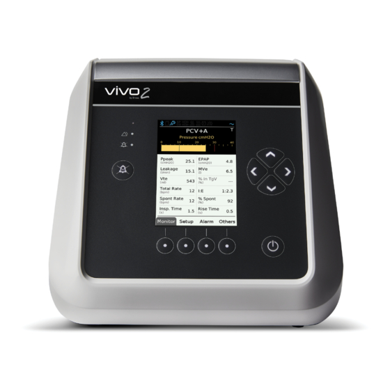
What is the Vivo 2? The Vivo 2 is a pressure ventilator capable of delivering non-invasive ventilatory support for the care of individuals who require long-term support from mechanical ventilation for respiratory insufficiency or respiratory failure, with or without obstructive sleep apnea. -
Page 11: Non Invasive Interfaces
1.2.4 Service Life The expected service life of the Vivo 2 is 5 years or 20,000 hours. Intended Use Vivo 2 is intended to provide non-invasive ventilation for patients weighing over 10 kg (22 lbs) who require long-term support or mechanical ventilation for respiratory impair- ment, with or without obstructive sleep apnea. -
Page 12: Intended Users
The User Manual contains the information intended for patients and lay operators. Training The lay operator shall be trained to basic knowledge of the Vivo 2 and in the specific operations they are assigned to perform. The training shall be based on the user manual and the responsible clinical personnel shall assess the level of training required for each lay operator. -
Page 13: Service Personnel
Training and Certification Service personnel shall be trained on the Vivo 2 and certified by Breas for being allowed to perform any service, repairs or other operations on the Vivo 2. The training consists of reading the services manual in full. -
Page 14: About This Manual
Vivo 2, a physician or responsible clinician should be contacted immediately. The following side effects may occur during the course of therapy with the Vivo 2, patients are advised to report any new or changing adverse effects to their physician: •... - Page 15 Icon Explanation Warning! Risk of death or personal injury. Warning! Risk of Cross-contamination. Warning! Risk of electric shock. Warning! Hot surface, risk of burns. Warning! Flammable material, risk of fire. Caution! Risk of equipment damage, loss of data, extra work, or unexpected results.
-
Page 16: Safety Information
Risk of Insufficient Ventilation Usage outside the specified operating conditions may cause reduced performance. The Vivo 2 must only be used in accordance with the operating conditions specified in this manual. Risk of Faulty Treatment Do not use the Vivo 2 in the event of: •... - Page 17 Modifying or using the ventilator with accessories that are not specified or approved by Breas may cause cardiac arrhythmia. The Vivo 2 must only be used in original and unmodified shape and only with acces- sories specified or approved by Breas Medical.
-
Page 18: Electricity - Warnings And Precautions
High voltage contact may cause cardiac arrhythmia. • Do not operate the Vivo 2 if it has a damaged power cord, power supply or casing. • To avoid electrical shock, only clean the Vivo 2 according to instructions in this manual. -
Page 19: Electromagnetic Compatibility And Electrostatic Discharge
Vivo 2. Please note some of these RF emitters may not be visible and the Vivo 2 can poten- tially be exposed to fields from these RF emitters without the user’s awareness. If... -
Page 20: Environment - Warnings And Precautions
Do not use the Vivo 2 in a toxic environment. Risk of Faulty Treatment If a room humidifier is used, place it at least 2 meters away from the Vivo 2. Risk of Faulty Treatment Do not use or store the Vivo 2 in a magnetic resonance (MR) environment. -
Page 21: Patient Circuit - Warnings And Precautions
Risk of Insufficient Ventilation Insufficient ventilation may cause transient hypoxia. The Vivo 2 ventilator is intended to be used with patient circuits with intentional leakage and compliant to ISO 17510. Recommended leak rate: 20 to 50 liters per minute at 10 cmH Failure to use a mask or accessory that minimizes rebreathing of carbon dioxide or permits spontaneous breathing can cause asphyxiation. - Page 22 This port prevents rebreathing by flushing the exhaled air. • The Vivo 2 should be turned on and the function of the leakage port should be checked before use: The pressurized air from the Vivo 2 causes a continuous flow of air through the leakage port, enabling flushing of exhaled air.
-
Page 23: Filter Usage - Warnings And Precautions
WARNING! Risk of Cross-Contamination Patient circuits might get contaminated by exhaled gases. To avoid cross-contamina- tion, always use a properly cleaned or a new patient circuit when the Vivo 2 is to be used by a new patient. NOTE For masks and accessories, always follow the manufacturer’s instructions. -
Page 24: Humidification And Heating - Warnings And Precautions
Risk of Insufficient Ventilation Insufficient ventilation may cause transient hypoxia. Do not use high resistance bacteria filter at the air outlet of the Vivo 2. High resist- ance bacteria filters placed between the air outlet and the patient interface may inter- fere with the operation of the patient disconnect function. - Page 25 Risk of Inflammation Incorrect connection of the ventilator may cause inflammation. The attachable humidifier is only enabled when the Vivo 2 is connected to the AC Power supply. Risk of Suffocation Installation of a water trap may be required if the condensation is extensive in the patient circuit when using a heated humidifier.
-
Page 26: Cleaning And Maintenance - Warning And Precautions
WARNING! Risk of Faulty Treatment Service and Maintenance of the Vivo 2 shall not be performed when the Vivo 2 is in use. WARNING! Risk of Electric Shock Cleaning with excessive water or opening the device’s casing without certified train-... -
Page 27: Oxygen Usage - Warning And Precautions
The presence of oxygen can speed up combustion of inflammable materials. Risk of Fire When oxygen is used with the Vivo 2, the oxygen flow must be turned off when the Vivo 2 is not operating. Oxygen delivered into the patient tubing may accumulate within the machine enclosure. -
Page 28: Mobile Use - Warning And Precautions
60% oxygen concentration: -5% deviation • 80% oxygen concentration: -7.5% deviation Mobile Use — Warning and Precautions This section applies if using the Vivo 2 during transit, for example on a wheel chair or in a car. WARNING! Risk of Suffocation Do not use the attachable humidifier during mobile use. - Page 29 WARNING! Risk of Electric Shock If connecting the Vivo 2 to an external DC power source, always use the DC DC Power Supply accessory. Connecting directly to an external DC power source may compromise the electrical isolation and cause an electric shock.
-
Page 30: Product Description
Product Description This section describes the main Vivo 2 medical electric equipment. For information about accessories and user replaceable spare parts., see .10 Accessories, page 121. Main Components Part Function Breas Part no. Ventilator unit Main unit. 228000 Power supply adapter... -
Page 31: Ventilator Front
Part Function Breas Part no. User Manual Instructions for use User’s manual: 007229 Clinician’s manual: 007230 For transportation, 007013 Carry bag when not in use. Patient circuit, 15 mm Delivers air to the 006712 patient Ventilator Front This section describes the front panel. - Page 32 Item Description Screen Displays pages with information, settings and commands. Directional buttons Moves between and selects objects on the current page. On/Off button Starts /stops treatment. Turn the ventilator On/Off. Navigation buttons Select pages according to the cor- responding label on the display. The navigation buttons can tempo- rarily be designated functions for replying to questions or requests...
-
Page 33: Ventilator Back
Ventilator Back Item Description Power port Port for connecting the power sup- ply. See 5.3 Connecting the Vivo 2 to Power Supply, page 60 Oxygen port Connection for low pressure/ bleed-in oxygen Patient air outlet Connection for patient circuit Patient air inlet... -
Page 34: Power Management
Power supply Y-cable is required. If a power source fails, the Vivo 2 will switch to the next source in priority and show a message on the display. If all available sources fail, the Power Failure alarm is given and the Vivo 2 shuts down. -
Page 35: Menus
Menus 3.5.1 Use the Menu The menu consists of four function sections: • Monitor • Setup • Alarm • Others a. Navigation buttons b. Active page indicator c. Directional buttons d. Page number indicator (for functions with several pages) Product Description User manual Doc. - Page 36 Selecting the Section to Display 1 Press the navigation button for the requested function page. ⇒The page is now displayed. 2 For functions with several pages grouped together, press the navigation button again to browse the pages. 3 For pages with menus, settings or additional information, press the Up and Down arrow buttons to select an item on the page.
- Page 37 1 Press the Up or Down arrow button to select the first selectable item on the page. ⇒The selected item is highlighted. 2 To select another item on the list, press the Up or Down arrow until it is highlighted. Note that items with read only information cannot be selected.
-
Page 38: The Monitor Page
3 Leave the sub page using the navigation buttons. Execute a Command 1 To execute a command, select it and press the right arrow button. ⇒ The command execution is started. Additional actions related to the command might be requested in event windows. -
Page 39: The Setup Pages
1. Current pressure 2. Low pressure alarm level 3. Set inspiration pressure level 4. High pressure alarm level For information about monitored values, see 6.5.1 Treatment Values Monitored by the Vivo 2 , page 68. 3.5.3 The Setup Pages The setup pages contain settings related to the treatment. - Page 40 WARNING! Risk of Asphyxia or Personal Injury Using incorrect settings may cause personal injury or severe medical conditions, such as hypercarbia, producing arterial acidemia. The therapy settings shall be based on a physician’s description. Changes to settings must be made by authorized clinical personnel only. Selecting a profile If profiles with preset treatment settings have been created, the profiles are selected from the Setup section.
-
Page 41: The Alarm
Default value: English (The language selection menu is displayed when the Vivo 2 is started for the first time.) Confirm Start/Stop If set to On, the user need to confirm that the treatment is to be stopped. - Page 42 Setting Description Display Light Value range: • On — Always lit at the selected intensity • Auto — Always lit, with automatic adjustment of the inten- sity with regards to the ambient light. • Delayed — The display is dimmed after about 30 seconds (time depends on usage mode and power source).
- Page 43 Usage log (containing at least 1 year data of non-clinical events, alarms and settings) 3.5.5.5 Clock Setting Description Time Sets the time for the Vivo 2. The time is used for logs and reports. Date Sets the date for the Vivo 2. The date is used for logs and reports.
- Page 44 Setting Description Alarm Clock Time Sets the alarm time for the alarm clock. Alarm Clock Volume Sets the volume for the alarm clock. NOTE The alarm clock works only when the ventilator is running on mains. 3.5.5.6 Compliance Data Description Setting / information Min daily use...
-
Page 45: Symbols On The Vivo 2
Nemko certifikation mark (NRTL/SCC accredited) Degree of protection provided by enclosure. The Vivo 2 is rated IP22, which means it is protected from touch by fingers and objects greater than 12 mm, and protected from water spray less than 15 degrees from vertical. - Page 46 Symbol Description Product number Serial number This product is a Medical Device. Date of manufacture Symbols on the Vivo 2 Back Symbol Description Oxygen connection port. Max 30 l/min and 100 kPa. Power connection port. Use approved power supplies only.
- Page 47 Additional Symbols on Parts and Accessories This section describes additional symbols for Vivo 2 detachable parts and accessories from Breas Medical. Each item, or its package, have the symbols that applies for the spe- cific accessory. Symbol Description Caution, hot surface Caution symbol, read the Accessory’s instructions for...
-
Page 48: Symbols On The Display
Symbol Description Effort belt port (not used) AC power port DC power port port Symbols on the Display 6 7 8 9 10 S S S 1. SD card inserted and working 2. Nurse call connected 3. Remote alarm connected 4. -
Page 49: Treatment Functions And Settings
Treatment Functions and Settings This chapter describes the modes, settings and parameters that controls the ventilation of the Vivo 2. All stated tolerances includes measurement uncertainty. The accuracies have been tested with all allowed configurations. Stated tolerances only disclose the maximum tolerance. - Page 50 Parameters and Modes The table below shows the parameters that are available for each mode. CPAP IPAP EPAP CPAP Breath Rate Inspiration Time Min insp. Time Max Insp Time Inspiratory Trigger Expiratory Trigger Rise Time Target Volume Max IPAP Min IPAP Auto-EPAP Min EPAP Max EPAP...
-
Page 51: Treatment Modes
(1) Without Target Volume (2) With Target Volume Treatment Modes This section describes the ventilating modes of the Vivo 2. 4.1.1 PCV+A — Pressure Controlled Ventilation (Assisted) In PCV+A mode, the ventilation is controlled by set values for pressure, inspiratory time, and rise time. -
Page 52: S - Spontaneous
Spontaneous breaths stop and an exhalation starts in three cases: • The inspiration flow has dropped to the value set for expiratory trigger. • The inspiration time is longer than the limit for maximal inspiration time or when inspiration time reaches 3 seconds. •... -
Page 53: T - Timed
The High Pressure Alarm limit is reached. 4.1.6 CPAP — Continuous Positive Airway Pressure In CPAP mode the Vivo 2 is applying a continuous positive pressure to the airways. The flow will automatically be adjusted to maintain the set CPAP level. Treatment Settings This section describes settings and parameters that affects the ventilating function of the Vivo 2. - Page 54 Auto-EPAP parameters When Auto-EPAP is on, the following parameters are enabled: Min EPAP The lowest possible EPAP value during the treatment. This is the EPAP value that the treatment is started with and that will be aimed for at periods of contin- uous normal breathing.
- Page 55 Min PS When Auto-EPAP is used together with TgV (Target volume), the pressure sup- port may vary between the set values for Min PS and Max PS for reaching the target volume. If setting high values for both Max PS and Max EPAP, the total pressure (EPAP and PS) is also limited by the Pressure Limit parameter.
-
Page 56: Ramp Up
EPAP Step The size of each incremental adjustment of the EPAP. Unit Defau- Resolution Tolerance ± (0.5 cmH + 5%) Relax Time The time a status of normal breathing shall be maintained before the algorithm is allowed to decrease the actual applied EPAP. Unit Defau- Resolution... -
Page 57: Ramp Pressure
4.2.4 Ramp Pressure The ramp pressure setting is used for defining the start and end pressure when Ramp Up and/or Ramp Down is configured. IPAP shall start at 2 cmH O above the configured Ramp Pressure. If the Ramp Pressure is set below EPAP, the EPAP pressure will start at the configured Ramp Pressure. -
Page 58: Heated Circuit Level
Default 4.2.8 Heated Circuit Level This setting defines the heating level, if Heated Circuit is set to On. Default 4.2.9 Patient Circuit This setting defines which patient circuit is used. Selection of Default 15 mm 15 mm 22 mm For 15 mm and 22 mm, predefined values for circuit resistance and compliance will be applied. Treatment Functions and Settings User manual Doc. -
Page 59: Prepare The Vivo 2 For Use
Prepare the Vivo 2 for Use Checking the Vivo 2 before First Use Before using the Vivo 2, perform the following checks. 1 Ensure that you have the equipment mentioned in 3.1 Main Components, page 30 2 Ensure that the equipment is in good condition. -
Page 60: Connecting The Vivo 2 To Power Supply
(accessory) listed in 10 Accessories, page 121. 1 Plug the DC plug by turning it into the power port at the back of the Vivo 2. 2 Make sure that the mains cord is connected to the power adapter (a). -
Page 61: Connecting The Patient Circuit
Read the chapter 2.4 Patient Circuit — Warnings and Precautions, page 21 Carefully to make sure all conditions are considered and met. The Vivo 2 is intended to be used with leakage circuits only. Recommended leak rate: 20 to 50 liters per minute at 10 cmH 1 Check that the circuit is clean and undamaged. -
Page 62: Connect The Heated Patient Circuit
Hold by the cuff and pull the circuit off from the patient interface. Do not pull by the tube. Power up the Vivo 2 This function check may be performed as a pre-use check or whenever the function of the Vivo 2 needs to be checked. Prepare the Vivo 2 for Use User manual Doc. 007229 D-3... - Page 63 • The audio pause LED lights yellow. • In about a second, both LEDs are turned off. If the test fails, do not use the Vivo 2. Contact your supplier of the Vivo 2 for a technical check. 3 Perform a pre-use test (select Others —> Pre-use Test).
-
Page 64: How To Use The Vivo 2
It is possible to choose how the machine will start and stop. If you want to confirm the starting and stopping or not, see 3.5.5.1 Device Settings, page 41 Confirm Start/Stop is set to On Make sure that the Vivo 2 is in Standby mode. How to Use the Vivo 2 User manual... -
Page 65: Stop The Treatment
• The audio pause LED lights yellow • In about a second, both LEDs are turned off If the function test beep absents, take the Vivo 2 out of use and contact your supplier of the Vivo 2 . Confirm Start/Stop is set to Off 1 Make sure that the Vivo 2 is in Standby mode. -
Page 66: Switch Off The Vivo 2
Switch Off the Vivo 2 Confirm Start/Stop is set to On 1 Make sure that the treatment is stopped and the Vivo 2 is in Standby mode. 2 Press the On/Off button. ⇒When the message “Do you want to turn off the ventilator?”... -
Page 67: Monitor Treatment
1 Press the Monitor navigation button. ⇒The Monitor page is now displayed. The monitor page displays treatment data monitored by the Vivo 2. It consists of a bar graph illustrating the current pressure and text area displaying monitored values in text. -
Page 68: Treatment Values Monitored By The Vivo 2
1. Current pressure 2. Low pressure alarm level 3. Set inspiration pressure level 4. High pressure alarm level 6.5.1 Treatment Values Monitored by the Vivo 2 • Ppeak (Peak pressure) is the highest pressure that is recorded during the latest inspira- peak tory phase. -
Page 69: Treatment Values Monitored By External Equipment
For monitoring the patient air oxygen saturation, an external monitoring device shall be connected to the patient circuit. The device shall comply with ISO 80601-2-55 and have a high oxygen level alarm. How to Use the Vivo 2 User manual Doc. 007229 D-3... -
Page 70: Using Accessories
Using Accessories This section describes how to use accessories provided by Breas Medical. 6.6.1 Using the Attachable Humidifier WARNING! Read the section 2.6 Humidification and Heating — Warnings and Precautions, page 24 before using the Vivo 2 with the attachable humidifier. - Page 71 Using the Attachable Humidifier for the First Time — Overview 1 Take out the air bypass unit by pressing the locking latch (a) and then pulling it out. 2 Fill the humidifier with water. How to Use the Vivo 2 User manual Doc. 007229 D-3...
- Page 72 1 If any treatment is running, stop it. 2 Push down the locking latch (a) and then pull the humidifier out. 3 If you will use the Vivo 2 without the humidifier, install the air bypass unit in place of the humidifier. Fill the Humidifier Duration of operation between humidifier refills Humidifier level (5): 12 hours.
- Page 73 CAUTION! • The water chamber must be detached from the Vivo 2 when filling water into the water chamber. • Use only distilled or sterilized water or boiled, chilled tap water in the humidifier water chamber. This is to reduce bacteria and mineral deposits.
- Page 74 (a) and then pulling it out. 3 Make sure the humidifier is correctly filled and push it into the Vivo 2 so the locking latch is engaged. ⇒A click indicates that the humidifier is correctly installed.
- Page 75 Risk of Burns If you remove and open the humidifier just after using the ventilator, ensure that you don’t touch the heater inside the humidifier since it can be very hot. How to Use the Vivo 2 User manual Doc. 007229 D-3...
-
Page 76: Using The Heated Circuit
Using the Heated Circuit WARNING! Read section 2.6 Humidification and Heating — Warnings and Precautions, page 24 before using the Vivo 2 with the heated circuit. NOTE The heated circuit requires connection to the Mains power supply to work. How to Use the Vivo 2 User manual Doc. -
Page 77: Using The Spo 2 Sensor
Using the SpO Sensor The SpO module (consisting of a SpO sensor, an electronic unit) is intended to meas- ure functional oxygen saturation of arterial hemoglobin (SpO2) and pulse rate. How to Use the Vivo 2 User manual Doc. 007229 D-3... - Page 78 The SpO module can be connected to the Vivo 2 (item 1 above) using the SpO adapter cable (007079) or to the accessory box (007000) in order to monitor and store measurements. The SpO measurements will be stored in the data memory which can be downloaded to a PC and viewed in the PC software.
-
Page 79: Using The Oxygen Supply Adapter
CAUTION! • When using the Vivo 2 with the SpO2 sensor, the Vivo 2 displays functional oxygen saturation measured by the sensor. • The following information concerns the light emitted by the SpO2 • Peak Wavelength (red): 660 nm •... -
Page 80: Using The Remote Alarm Unit
Connect the Oxygen supply 1 Connect the oxygen adapter (article no. 005032) to the oxygen supply’s tube. 2 Connect the oxygen adapter to the oxygen port at the back of the Vivo 2. See 3.3 Ventilator Back , page 33 for detailed information. -
Page 81: Using The Protective Cover
2 Connect the remote alarm cable to the Nurse call/ Remote alarm port on the accessory box. 3 Start the remote alarm unit. 4 Trigger an alarm on the Vivo 2 and check that it activates the remote alarm system. 6.6.6 Using the Protective Cover The protective cover is intended for mobile use of the Vivo 2 in hospitals, institutions and home care environments. -
Page 82: Using The Lightweight Mobility Bag
6.6.8 Using the Y-Cable The Y-cable is used for connecting the Vivo 2 to both mains and external DC at the same time. see 5.3 Connecting the Vivo 2 to Power Supply, page 60. When both power sour- ces are available, the mains will be used. - Page 83 The maximum load of the trolley basket is 0.9 kg (2 lbs). • The maximum load of the trolley rail is 9 kg (20 lbs). No maintenance is required. How to Use the Vivo 2 User manual Doc. 007229 D-3...
-
Page 84: Basic Troubleshooting
The humidifier doesn’t work properly. If the humidifier is incorrectly assembled, disassemble it and then assemble it correctly. If the air is dry despite using the humidi- fier, increase the level of humidification. How to Use the Vivo 2 User manual Doc. 007229 D-3... -
Page 85: Alarms
The alarm settings are maintained during power failure. Operator’s Position The alarm priority indications are designed to be recognized from a distance of 4 meters and by an angle of 50 ° from the normal of the Vivo 2 display. 7.1.1 Checking the Operator’s Position 1 Activate an alarm. -
Page 86: Handle Alarms
Handle Alarms 7.2.1 Identify an Alarm Condition If an alarm condition is detected, the Vivo 2 main unit and the remote alarm unit (if connected) will alarm without delay. The alarms will remain active until the alarm condi- tion is resolved. - Page 87 Alarm Message on the Screen The name of the active alarm is displayed on the screen. • High priority alarms Red highlight color. • Medium priority alarms Yellow highlight color. For detailed information about specific alarms, see 7.3 Physiological Alarms, page 92 and 7.4 Technical Alarms, page 105.
-
Page 88: Pause The Alarm Sound
To reset an alarm, correct the cause of the alarm condition. ⇒Once the cause is corrected, the alarm disappears from the display. WARNING! If an alarm condition cannot be corrected, take the Vivo 2 out of use and contact your supplier of the Vivo 2 e. 7.2.4 View Historical Alarms To view historical alarms, press the Alarm button until Alarm/Event history is shown. -
Page 89: Adjust The Alarm Sound Level
7.2.5 Adjust the Alarm Sound Level Alarm Sound Level is found in the Alarm Settings. Alarms User manual Doc. 007229 D-3... - Page 90 1 Press the Alarm navigation button until the Alarm settings page with Alarm Sound Level is shown. 2 Press the Down or Up arrow button to select the Alarm Sound Level setting. 3 Press the Left or Right arrow buttons to adjust the sound level. Alarms User manual Doc.
- Page 91 4 Press the Up arrow button to finish the adjustment by deselecting the setting. 5 When finished with the sound level adjustment, check that the alarm can be received at the operator’s position, see 7.1 Operator’s Position, page 85. Alarms User manual Doc.
-
Page 92: Physiological Alarms
A full breath is performed with maximum pressure below the alarm limit. Ventilator action The Vivo 2 will continue treatment according to the current settings. The actual breath is however terminated if the High Pressure alarm limit is reached. Setting range •... -
Page 93: Low Pressure Alarm
Description Alarm text Low Pressure Priority High Alarm condition A Low Pressure alarm will be given when the Vivo 2 pres- sure fails to reach the low pressure alarm limit for 15 seconds. Possible cause • Disconnection of patient circuit. -
Page 94: High Breath Rate Alarm
• Too sensitive setting of the inspiratory trigger setting. Reset criteria The breath rate goes below the alarm limit. Ventilator action The Vivo 2 will continue treatment according to the current settings. Setting range • 10 bpm to 50 bpm •... -
Page 95: Low Breath Rate Alarm
Decrease in the patient’s spontaneous breathing. • Circuit disconnection. Reset criteria The breath rate goes above the alarm limit. Ventilator action The Vivo 2 will continue treatment according to the current settings. Setting range • 4 bpm to 30 bpm. •... -
Page 96: High Minute Volume Alarm
• Increased breath rate. Reset criteria The minute volume goes below the alarm limit. Ventilator action The Vivo 2 will continue treatment according to the cur- rent settings. Setting range • 1 l. to 40 l. • Setting resolution 0.5 l. -
Page 97: Low Minute Volume Alarm
• Decreased breath rate. Reset criteria The minute volume goes above the alarm limit. Ventilator action The Vivo 2 will continue treatment according to the cur- rent settings. Setting range • 1 l. to 30 l. • Setting resolution 0.5 l. -
Page 98: Rebreathing Alarm
Incorrect patient circuit. • Obstructed or removed CO port from leakage circuit. Reset criteria The leakage is back within limits. Ventilator action The Vivo 2 will continue treatment according to the current settings. Setting range • • Alarms User manual... -
Page 99: Apnea Alarm
Circuit disconnection. • Inspiratory Trigger is set too high. Reset criteria Inspiratory effort detected by the Vivo 2. Ventilator action The Vivo 2 will continue treatment according to the current settings. Setting range • 5 to 60 s. • Setting resolution 5 s below 15 s. -
Page 100: High Epap Alarm
• The patient has removed the mask. • Circuit disconnection. Reset criteria The leakage is back within limits. Ventilator action The Vivo 2 will continue treatment according to the current settings Setting range • • 7.3.10 High EPAP Alarm Property... -
Page 101: Low Epap Alarm
Possible cause • Excessive leakage. Reset criteria EPAP has gone above the alarm limit (higher than 30% below the set value). Ventilator action The Vivo 2 will continue treatment according to the current settings. Setting range • • 7.3.12 High SpO... -
Page 102: Low Spo
7.3.13 Low SpO Alarm Property Description Alarm text Low SpO2 Priority High Definition A Low SpO alarm will be given when the measured SpO below the alarm limit for 30 seconds. Possible cause • Too low flow of bleed-in oxygen. •... -
Page 103: High Pulse Rate Alarm
Bad positioning of the finger probe. Reset criteria The pulse rate goes back below the alarm limit. Ventilator action The Vivo 2 will continue treatment according to the current settings. Setting range 30 to 230 bpm (beats per minute) Setting resolution... -
Page 104: Low Pulse Rate Alarm
• Insufficient ventilatory support. Reset criteria The pulse rate goes back above the alarm limit. Ventilator action The Vivo 2 will continue treatment according to the current settings. Setting range 30 to 230 bpm (beats per minute) Setting resolution 5 bpm (beats per minute) This alarm requires a connected SpO sensor. -
Page 105: Technical Alarms
External power supply connected to ventilator. Ventilator action The Vivo 2 stops the treatment, turns off the display and gives the Power Fail alarm for at least 2 minutes. If power is restored within the alarm time, the ventilator will automatically resume treatment with current settings. -
Page 106: Spo Sensor Failure / Disconnected Alarm
Reset criteria Normal communication with the sensor is re-established. An information message remains until acknowledged by the user. Ventilator action The Vivo 2 will continue treatment according to the cur- rent settings. 7.4.4 Artifact This alarm requires a connected SpO sensor. -
Page 107: Ambient Pressure Compensation Lost
Ventilator action The Vivo 2 will continue treatment according to the current settings. Normal atmospheric pressure at sea level will be used as approximation for the temporary ambient pressure compen- sation. -
Page 108: Flow Sensor Failure
Reset criteria Correct data from the sensor is received again. An information message remains until acknowledged by the user. Ventilator action The Vivo 2 will continue treatment but with the following limitations: • Monitoring of leakage is disabled. • Volume measurements are disabled. -
Page 109: Cleaning And Maintenance
3 If any cable connected accessories (like the SpO sensor or the accessory box) are used, disconnect them. 4 Clean the outside of the Vivo 2 using a lint free cloth moistened with a mild soap solution and / or ethanol 70%. Cleaning and Maintenance User manual Doc. -
Page 110: Air Pathway Disinfection
Clean and Replace Patient Air Inlet Filters The Vivo 2 patient air inlet filters are located inside a magnetic filter holder at the back of the ventilator. The table below describes the filters and their minimum maintenance intervals. - Page 111 Replace: every 4th week or when assign- ing the Vivo 2 to a new patient. * If the Vivo 2 is used in an environment with high grades of pollen or pollutions, shorter intervals might be required. 1 Turn off the Vivo 2 and place it on a clean dust free surface.
-
Page 112: Disposal
5 Reinstall the filter holder on the Vivo 2. Disposal The ventilator, any accessories and all replaced parts must be disposed of and recycled in accordance with the local environmental regulations regarding the disposal of used equipment and waste. Contact your service provider for information regarding the dis- posal procedure. -
Page 113: Technical Specifications
Technical Specifications Ventilator Size and Weight Property Value Dimensions (WxHxD) 166 x 185 x 200 mm Weight 1,6 kg Power Supply Mains Power Supply Property Value Mains Power Supply 100–240 V AC tolerance: +10%/-20%, 50 to 60 Hz, max 1.2 A. The approved AC/DC supply listed in 10 Accessories, page 121 must be used. -
Page 114: Environmental Conditions
Normal Operation +5°C to +40°C Temperature Precautions • Be careful not to position the Vivo 2 in an extra warm place, such as in direct sunlight or above a radiator. • Caution should be exercised if the room tempera- ture is higher than 36°C (97°F). -
Page 115: Pneumatic Diagram
Environmental Condition Specification Humidity RH from 15% to 95%, non-condensing. Ambient Pressure Range 70 to 106 kPa This corresponds to ~ 315 m below sea level to ~3000 m above sea level Ventilator ingress protection IP 22 Mechanical ingress protection: protected from touch by fingers and objects greater than 12.5 Liquid ingress protection: The device withstands dripping water(equivalent to 3 mm rainfall... - Page 116 Number Description Vivo 2 Patient circuit Leakage port / Patient interface connection Patient With Bypass Unit Number Description Air inlet (Ambient room air intake) Blower Sensors Air bypass unit Air outlet (Breathing air to the patient) Technical Specifications User manual...
-
Page 117: Technical Data
With Humidifier Number Description Air inlet (Ambient room air intake) Blower Sensors Humidifier Air outlet (Breathing air to the patient) Cartridge heater The humidification output is controlled by the ventilator by regulating the power to the cartridge heater in the humidifier. Technical Data Noise Levels Property... - Page 118 Property Value Maximum sound pressure level 40 dB(A) SPL according to applicable standards. Measured at a distance of 1 meter, according to standard. Maximum sound power level 48 dB (A) according to applicable standards. Measured at a distance of 1 meter, according to standard.
- Page 119 CPAP Maximum Dynamic Pressure Variations Device with standard tube / Device with worst case VBS (external humidifier with 22 mm tube and bacterial filter) Pressure [cmH 10 bpm 15 bpm 20 bpm 0.4/1.0 0.5/1.2 0.5/1.5 0.4/1.0 0.5/1.2 0.5/1.5 0.4/1.0 0.5/1.2 0.5/1.5 0.4/1.0 0.5/1.2...
- Page 120 Temperature on applied part • Ventilator enclosure: 52°C NC, 53°C SFC (NC=normal condition, SFC=single fault condition) • Accessory box enclosure: 42°C NC • Y-cable box: 42°C NC • Humidifier enclosure: 46°C NC, 55°C SFC • Heated circuit: 42°C NC, 59°C SFC Technical Specifications User manual Doc.
-
Page 121: Accessories
Accessories The accessories described in this section, together with the medical electric equipment defined in chapter 3.1 Main Components, page 30, constitute the Vivo 2 medical electric system. CAUTION! Responsibility for System Accessory equipment connected to the analogue and digital interfaces must be certi- fied according to the respective IEC standards (e.g. - Page 122 Circuit: Single limb 22 mm, disposable Function: Delivers air to the patient, applied part Part No: 004465 Circuit: Single limb 15 mm, disposable Function: Delivers air to the patient, applied part Part No: 006712 Heated Circuit Function: Delivers air to the patient, applied part.
- Page 123 Attachable humidifier Function: Humidifies the patient air. For non-invasive use only. Part No: 006977 Air Bypass Unit Function: Directs the patient air flow, if the attachable humidifier is not used. Part No: 006983 Filter Holder Function: Holder for air inlet filters Part No: 007598 Air Inlet Filter, Grey Function: Coarse air inlet filter, user...
-
Page 124: Accessories
Part No: 007963 10.2 Accessories RRC CAR70M DC/DC Power Supply Function: Power supply adapter for the Vivo 2 shall be used for connecting the Vivo 2 to an external DC source. Part No: 006995 Y Cable Function: Power supply cable, for connecting to both AC and DC power supply. - Page 125 Trolley Function: Mobile use, transportation Part No: 007384 Mounting Bracket Function: Bracket to mount the Vivo 2 to the trolley Part No: 006998 Accessories User manual Doc. 007229 D-3...
- Page 126 • Nurse call cable or Remote alarm • sensor (Might also be con- nected directly to the Vivo 2, if no other measurement or communi- cation accessories are used.) Part No: 007000 Remote alarm with cable Function: Monitor Vivo 2 alarms...
- Page 127 Nurse call cable Function: Connect the ventilator to a hospital nurse call system Part No: NO: 006365 NC: 006364 10 kΩ, NO: 006363 10 kΩ, NC: 006362 module Function: Connection interface Part No: 006369 sensor Function: Finger Clip SpO sensor Part No: Adult: 006589 Paediatric: 006590...
- Page 128 Function: Support software for follow- up on patient treatment. Part No: 007067 USB Cable Function: USB cable for transferring data between a PC and the Vivo 2. Part No: 005757 Memory card Function: Storage and transfer of set- tings, patient data and usage data...
- Page 129 Oxygen Adapter, Low Pressure Function: Connection of oxygen supply. Part No: 005032 Accessories User manual Doc. 007229 D-3...
-
Page 131: Appendices
Appendices Appendix: Appendices Doc. 007229 D-3... -
Page 132: A Patient Settings Record
Patient Settings Record This page can be copied and used for noting the patient’s settings. Patient: Clinic: Vivo SN: Set by: Date: Treatment Settings Ventilation Mode: IPAP: EPAP: CPAP: Breath Rate: Patient Insp. Time: Circuit: Min Insp. Max Insp. Time: Time: Insp. - Page 133 Treatment Settings – Auto EPAP Pressure Min EPAP Limit EPAP Step Max EPAP Relax Time Min PS Max PS Notes Appendix: A Patient Settings Record Doc. 007229 D-3...
-
Page 134: Bfaa Compliance
Breas Medical has successfully completed testing for the ventilator System. The ventilator System complies with RTCA/DO-160, Section 21, Category M and can be considered FAA compliant. Some airlines may require advance notification before travel, and devices may need to be operated by battery. Breas Medical rec- ommends that customers check with their airline. - Page 135 Index pausing ......88 Alarm time ......43 Alarm volume.
- Page 136 Electromagnetic compatibility..19 Languages ......41 Electrostatic discharge .
- Page 137 Power supply Treatment connect ......60 start....... . . 64 Pressure Controlled Ventilation Treatment data .
Need help?
Do you have a question about the Vivo 2 and is the answer not in the manual?
Questions and answers