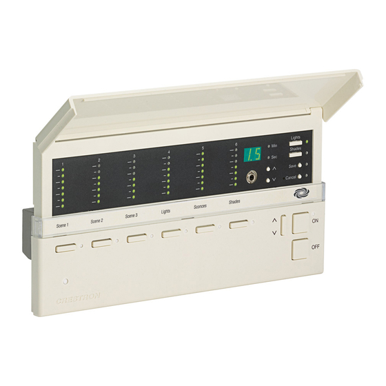
Crestron iLux CLS-C6 Series Operation Manual

Crestron iLux CLS-C6 Series Operation Manual

Integrated lighting system
Hide thumbs Also See for iLux CLS-C6 Series:

Advertisement

Crestron CLS/CLSI-C6 & CLS/CLSI-C6M
®
iLux
Integrated Lighting System
Operations Guide

Advertisement

Table of Contents
loading

Summary of Contents for Crestron iLux CLS-C6 Series

  • Page 1 Crestron CLS/CLSI-C6 & CLS/CLSI-C6M ® iLux Integrated Lighting System Operations Guide...
  • Page 2 Underwriters Laboratories, Inc. in the United States and/or other countries. Other trademarks, registered trademarks and trade names may be used in this document to refer to either the entities claiming the marks and names or their products. Crestron disclaims any proprietary interest in the marks and names of others.
  • Page 3: Table Of Contents

    Crestron CLS-C6/C6M & CLSI-C6/C6M iLux Integrated Lighting System Contents iLux Integrated Lighting System: CLS-C6/C6M & CLSI-C6/C6M Introduction ..........................1 Features and Functions ....................1 Specifications ......................4 Physical Description ....................6 Setup ............................10 Network Wiring ......................10 Identity Code ......................10 Installation .........................
  • Page 4 Appendix E: Button Functions ....................74 Appendix F: Room Combining ....................81 Appendix G: RC5 Code Expansion ..................84 Return and Warranty Policies ....................86 Merchandise Returns / Repair Service ..............86 Crestron Limited Warranty ..................86 Operations Guide – DOC. 6347E Contents • ii...
  • Page 5: Ilux Integrated Lighting System: Cls-C6/C6M & Clsi-C6/C6M

    Crestron CLS-C6/C6M & CLSI-C6/C6M iLux Integrated Lighting System iLux Integrated Lighting System: CLS-C6/C6M & CLSI-C6/C6M Introduction ® The CLS/CLSI-C6 and CLS/CLSI-C6M iLux units are complete, integrated wall-mounted lighting systems that can function as standalone devices or as part of a ®...
  • Page 6 The selected scene is indicated by a white LED beside each button, and the customizable label strip allows each button to be clearly labeled using Crestron Engraver software or standard 3/8" tape labels. Dimming levels and shade positions are displayed graphically on 6 green LED bargraphs accessible behind the flip-up front cover.
  • Page 7 Crestron’s optional infrared remote control (sold separately). Multipoint Keypad Control Up to 16 Crestron keypads may be connected to a single CLS-C6, providing versatile multipoint control for rooms with multiple entrances or work areas. Individual keypad buttons can be programmed to work through the master unit or can target specific slave units for maximum control and room management.
  • Page 8: Specifications

    RS-232 Interface via C2N-IO The CLS-C6 can be controlled from a third party controller or a PC program via the ASCII command set. The Crestron serial convertor module, C2N-IO (sold separately), is used to route packets between the CLS-C6 and the third party controller.
  • Page 9 Crestron CLS-C6/C6M & CLSI-C6/C6M iLux Integrated Lighting System CLS-C6 Specifications (Continued) DETAILS SPECIFICATION 3, 4 Control System Update Files 2-Series Control System Version 2.004.CUZ or later IR Receiver Reception Frequency 36 kHz Requires CLS-IRHT8 IR remote (sold separately). Built-In Motion Detector...
  • Page 10: Physical Description

    Larger loads and additional load types can also be supported using Crestron CLS-EXP Series expansion modules (sold separately). The latest versions can be obtained from the Crestron Web site. Refer to NOTE after last footnote. Crestron 2-Series control systems include the AV2 and PRO2. Consult the latest Crestron Product Catalog for a complete list of 2-Series control systems.
  • Page 11 Crestron CLS-C6/C6M & CLSI-C6/C6M iLux Integrated Lighting System CLS-C6M Overall Dimensions 2.38 in 8.89 in (60 mm) (226 mm) 4.48 in (114 mm) 1.88 in (48 mm) 0.59 in 0.72 in (15 mm) (18 mm) CLS-C6/ CLS-C6M/ CLSI-C6 CLSI-C6M CLS-C6M Front Panel...
  • Page 12 Designer software program. Mini Phone Jack Use this 3.5mm TRS mini-phone jack, located on the front panel, as an RS-232 programming port, to communicate with the iLux Designer and Crestron ™ Toolbox to configure the unit, and to upgrade the unit’s firmware.
  • Page 13 Crestron CLS-C6/C6M & CLSI-C6/C6M iLux Integrated Lighting System Connectors, Controls, & Indicators (Continued) CONNECTORS DESCRIPTION CONTROLS, & INDICATORS Lights Use this switch to select the Lights mode. The LED Button and LED illuminates when the mode is selected. Refer to “Lights Mode”...
  • Page 14: Setup

    Provide sufficient power to the system. CAUTION: Insufficient power can lead to unpredictable results or damage to the equipment. Use the Crestron Power Calculator to help calculate how much power is needed for the system (www.crestron.com/calculators). For networks with 20 or more devices, use a Cresnet Hub/Repeater (CNXHUB) to maintain signal quality.
  • Page 15: Configuring The Cls-C6

    Designer, but permits basic functional setup without having to use a PC. In addition, some aspects of the CLS-C6’s operation can be modified only via certain Crestron Toolbox console commands. (Refer to “Console Command Settings” on page 25 for details. Refer also to “Appendix B: Console Commands” on page 54 for details on all applicable console commands.)
  • Page 16 Crestron CLS-C6/C6M & CLSI-C6/C6M iLux Integrated Lighting System graph lights (and the display shows - -) to indicate that the level of the lighting load does not change when that scene is recalled. To change the shade presets for that scene press the Shades button; the Shades LED lights.
  • Page 17 Crestron CLS-C6/C6M & CLSI-C6/C6M iLux Integrated Lighting System Setup Mode Mnemonics TWO-DIGIT DESCRIPTION DISPLAY Scene Programming Setup lighting load Load types Setup lighting load Low-End limits Setup lighting load High-End limits Setup Lockout mode button Functions (i.e. recall scene, toggle scene, shades control, etc.)
  • Page 18 Crestron CLS-C6/C6M & CLSI-C6/C6M iLux Integrated Lighting System displayed value is be saved, but the light level is limited to the programmed limits. • If a lighting load is defined as an “unused” load type, the bar graph for that lighting load has all LEDs off.
  • Page 19 Crestron CLS-C6/C6M & CLSI-C6/C6M iLux Integrated Lighting System Load Type Number LEDs Default LowEnd / HighEnd Unused all off 0 / 100 Incandescent – default top 1 on 0 / 100 top 2 on 0 / 100 top 3 on...
  • Page 20 Crestron CLS-C6/C6M & CLSI-C6/C6M iLux Integrated Lighting System Setup High-End Levels (HE) This option allows setting of the “full on” level of the lighting loads below their maximum brightness. To set the high-end levels for the six lighting loads: •...
  • Page 21 Crestron CLS-C6/C6M & CLSI-C6/C6M iLux Integrated Lighting System When the button is released, the LED for that button should flash once to indicate that programming took place. Next, use the up/down button to scroll to the next function and value to be assigned, and assign the desired buttons.
  • Page 22 Crestron CLS-C6/C6M & CLSI-C6/C6M iLux Integrated Lighting System • The first mode to be displayed is the current mode. • When programming from the front panel, exit time cannot be adjusted or displayed. If it has not been changed with iLux Designer, or SIMPL, it is the default of 30 minutes.
  • Page 23 Crestron CLS-C6/C6M & CLSI-C6/C6M iLux Integrated Lighting System • All shade controllers of a given type are assigned to a single shade group. Use the “AS” option to change them. CAUTION: If there are SSC shade controllers on the network that do not have a functional shade connected to channel 1, shade control may not operate properly.
  • Page 24 Crestron CLS-C6/C6M & CLSI-C6/C6M iLux Integrated Lighting System function front panel buttons to jump to a specific shade group.) The front panel LED corresponding to the selected shade group lights. • While in AS mode, the bar graphs indicates the status of each of the six shade groups: if no controllers are assigned, all LEDs remain off;...
  • Page 25 Crestron CLS-C6/C6M & CLSI-C6/C6M iLux Integrated Lighting System Photocell Test (Ph) This Setup mode is used to test photocell output. NOTE: Auto-Discovery must be performed before the CLS-C6 recognizes a GLS-LOL photocell. The photocell must also be installed and wired to a GLS-SIM or C2N-CBD-P Keypad.
  • Page 26 Crestron CLS-C6/C6M & CLSI-C6/C6M iLux Integrated Lighting System • Use the rocker buttons below each load to adjust each individual sensitivity level. Pressing the right-half of the rocker button lowers the sensitivity, increasing light output level. Pressing the left-half of the rocker button raises sensitivity, decreasing light output level.
  • Page 27: Configuring With Ilux Designer

    Configuring with iLux Designer The Crestron iLux Designer program software supplied with all of the CLS-C6 series units configures the CLS-C6 as an independent, standalone device or as a network device in a Crestron network control system (Cresnet system).
  • Page 28 Crestron Engraver version 2.5.0 or later* Crestron Database version 17.3.0 or later* *Required only if using Crestron Engraver to prepare custom labeling. The following sections provide a brief description of the iLux Designer functions. Refer to the iLux Designer online help for detailed explanations.
  • Page 29: Console Command Settings

    The "Keypads" screen allows up to 16 remote keypads to be added; specify the remote keypad type; define the action type, action, and target of each button on that keypad. Crestron Engraver can also be launched to create an engraver project for each remote keypad.
  • Page 30: Replacing The Function Button Label

    Crestron CLS-C6/C6M & CLSI-C6/C6M iLux Integrated Lighting System IR reception is enabled (or disabled) iLux> To disable IR reception, type <IR disable> and press Return. The system displays: IR reception is disabled iLux> To enable IR reception, type <IR enable> and press Return. The system...
  • Page 31 Crestron CLS-C6/C6M & CLSI-C6/C6M iLux Integrated Lighting System To replace the label on the unit: Remove the front panel assembly by carefully pulling out and up from the bottom edge. Carefully pull the label cover from the top edge at each side of the unit.
  • Page 32: Programming Software

    Have a question or comment about Crestron software? Answers to frequently asked questions (FAQs) can be viewed in the Online Help section of the Crestron Web site. To post a question or view questions submitted to Crestron’s True Blue Support, log in at www.crestron.com/support. First-time users must establish a user account.
  • Page 33: Programming With Simpl Windows

    SIMPL Windows is Crestron’s premier software for programming Crestron control systems. It is organized into two separate but equally important “Managers”: Configuration and Program. Configuration Manager is the view where programmers “build” a Crestron control Configuration Manager system by selecting hardware from the Device Library.
  • Page 34 Net ID of each unit. Refer to “Identity Code” on page 10. Program Manager Program Manager is the view where programmers “program” a Crestron control system by assigning signals to symbols. The symbol can be viewed by double clicking on the icon or dragging it into Detail View.
  • Page 35: Uploading And Upgrading

    The RS-232 (or COMPUTER) port on the CLS-C6 connects to the serial port on the PC via a serial cable (Crestron STCP-502 or equivalent): Use the Address Book in Crestron Toolbox to create an entry using the expected serial communication protocol (RS-232, auto-detect baud rate, no parity, 8 data bits, 1 stop bit, XON/XOFF disabled, RTS/CTS disabled).
  • Page 36: Programs And Firmware

    SIMPL Windows or Crestron Toolbox. Firmware Check the Crestron Web site to find the latest firmware. (New users may be required to register to obtain access to certain areas of the site, including the FTP site.) Upgrade CLS-C6 firmware via Crestron Toolbox.
  • Page 37: Operation

    Crestron CLS-C6/C6M & CLSI-C6/C6M iLux Integrated Lighting System Operation The iLux always operates in one of four modes. The Setup mode is used to redefine many of the CLS-C6 settings. Details regarding the Setup mode are given in “Setup Mode” on page 12.
  • Page 38 Crestron CLS-C6/C6M & CLSI-C6/C6M iLux Integrated Lighting System may be specified. (Refer to “Configuring With iLux Designer” on page 23 for details.) • Recall-scene (specify scene number OFF, ON, 1-15). Refer to “Recall-scene buttons” below. • Toggle-scene (specify scene number ON, 1-15). Refer to “Toggle-scene buttons”...
  • Page 39 Crestron CLS-C6/C6M & CLSI-C6/C6M iLux Integrated Lighting System Toggle-Scene Buttons • Used to alternately recall a scene or turn scene lights off (i.e., have the specified lighting loads go to off, in the specified time). • The toggle scene function should not be assigned to any scene that includes shades.
  • Page 40: Ir Receiver

    Crestron CLS-C6/C6M & CLSI-C6/C6M iLux Integrated Lighting System IR Receiver Functions can also be triggered through the built in RC5 IR receiver, using the optional CLS-IRHT8 remote or a third-party remote. Refer to “Appendix G: RC5 Code Expansion” on page 84 for details.
  • Page 41: Load Shedding (Demand Response)

    Crestron CLS-C6/C6M & CLSI-C6/C6M iLux Integrated Lighting System When the Override mode is disengaged, all loads revert to their previous values. While in Override mode, all slave units are placed into Override mode as well, regardless of the room combining status.
  • Page 42 Crestron CLS-C6/C6M & CLSI-C6/C6M iLux Integrated Lighting System • Unit 2 (Cresnet ID 0xC6): Defeat Occ Sensors/lockout front panel controls • Unit 3 (Cresnet ID 0xC7): Recall scenes 14/15 • Unit 4 (Cresnet ID 0xC8): Override mode/load shed For these units, DIP switches 0, 1, 2, and 3 determines whether the inputs are normally open, normally closed, active high or active low.
  • Page 43 Crestron CLS-C6/C6M & CLSI-C6/C6M iLux Integrated Lighting System To exit Lights mode, press the Lights button again (or press Cancel), and the LED goes off. The unit returns to Standard mode. (Also, if no adjustments are made within 1 minute, the unit reverts to Standard mode.) Pressing the Shades button automatically exits Lights mode and enters Shades mode.
  • Page 44 Crestron CLS-C6/C6M & CLSI-C6/C6M iLux Integrated Lighting System of that shade group terminates, and the new command takes precedence. To manually adjust this channel after that, release and re- press the button. The unit remains in Shades mode. To exit Shades mode, press the Shades button again (or press the Cancel button); the LED extinguishes and the unit returns to Standard mode.
  • Page 45: Problem Solving

    To ensure optimum performance over the full range of the installation topology, use Use the Right Wire Crestron Certified Wire only. Failure to do so may incur additional charges if support is required to identify performance deficiencies because of using improper wire.
  • Page 46: Reference Documents

    Cresnet power usage of the entire chain. If the unit is run from a Crestron system power supply network port, the Cresnet power usage of that unit is the Cresnet power usage of the entire run. The wire gauge and the Cresnet power usage of the run should be used in the following equation to calculate the cable length value on the equation’s left side.
  • Page 47: Future Updates

    Crestron CLS-C6/C6M & CLSI-C6/C6M iLux Integrated Lighting System To post a question about Crestron products, log onto the online help section of the Crestron Web site (www.crestron.com/onlinehelp). First-time users must establish a user account to fully benefit from all available features.
  • Page 48: Appendix A: Supported Devices

    Crestron CLS-C6/C6M & CLSI-C6/C6M iLux Integrated Lighting System Appendix A: Supported Devices The CLS-C6 local devices network supports up to 16 remote devices consisting of keypads, shade controllers, touch screens, and additional CLS-C6 units. Keypads Up to 16 keypads can be added on the local devices network. The following table lists default button functions for the keypad types currently supported.
  • Page 49 Crestron CLS-C6/C6M & CLSI-C6/C6M iLux Integrated Lighting System Supported Keypads (Continued) KEYPAD TYPE BUTTON BUTTON DEFAULT FUNCTION LAYOUT NUMBER CNX-B12 / Recall Scene 1 C2N-DB12 Recall Scene 2 Recall Scene 3 Recall Scene 4 9 10 Recall Scene 5 11 12...
  • Page 50: Shade Controllers

    Crestron CLS-C6/C6M & CLSI-C6/C6M iLux Integrated Lighting System Shade Controllers A maximum of 16 shade controllers can be added to the local devices network. The following shade controllers are currently supported (all sold separately): • C2N-SSC-2* • C2N-SDC • C2N-SDC-DC NOTE: The two channels on these shade controllers are labeled 1 &...
  • Page 51 Crestron CLS-C6/C6M & CLSI-C6/C6M iLux Integrated Lighting System Joins Digital Command Joins External functions and their feedbacks are only supported by the iLux master. The slave iLux(s) do not support external functions. Programmable Joins 1-20 and partition joins and their feedback are only supported for the master iLux.
  • Page 52 Crestron CLS-C6/C6M & CLSI-C6/C6M iLux Integrated Lighting System Digital Command Joins (from Touch Screen to CLS-C6) (Continued) JOIN DESCRIPTION Fade time up for Edit Scene Fade time down for Edit Scene Enable occupancy reporting Enable entry scene Disable entry scene...
  • Page 53 Crestron CLS-C6/C6M & CLSI-C6/C6M iLux Integrated Lighting System Digital Command Joins (from Touch Screen to CLS-C6) (Continued) JOIN DESCRIPTION Photocell dim min level up light zone 3 Photocell dim min level up light zone 4 Photocell dim min level up light zone 5...
  • Page 54 Crestron CLS-C6/C6M & CLSI-C6/C6M iLux Integrated Lighting System Digital Feedback Joins (from CLS-C6 to Touch Screen) (Continued) JOIN DESCRIPTION 6160/6161/6162 Shade group 2 moving/last dir. Open/last dir. Close 6170/6171/6172 Shade group 3 moving/last dir. Open/last dir. Close 6180/6181/6182 Shade group 4 moving/last dir. Open/last dir. Close 6190/6191/6192 Shade group 5 moving/last dir.
  • Page 55 Crestron CLS-C6/C6M & CLSI-C6/C6M iLux Integrated Lighting System Digital Feedback Joins (from CLS-C6 to Touch Screen) (Continued) JOIN DESCRIPTION 8000-8399 Same as joins 6000-6355 but from Slave 5 --> touch screen 8400-8799 Same as joins 6000-6355 but from Slave 6 --> touch screen 8800-8199 Same as joins 6000-6355 but from Slave 7 -->...
  • Page 56 Crestron CLS-C6/C6M & CLSI-C6/C6M iLux Integrated Lighting System Analog Feedback Joins (from CLS-C6 to Touch Screen) (Continued) JOIN DESCRIPTION 180-199, 480-499 Same as joins 20-39, 300-339 for slave 8 Photocell sensitivity level feedback light zone 1 Photocell sensitivity level feedback light zone 2...
  • Page 57 Crestron CLS-C6/C6M & CLSI-C6/C6M iLux Integrated Lighting System Bidirectional Serial Joins Bidirectional Serial Joins (to/from CLS-C6 and Touch Screen) JOIN DESCRIPTION 1-16 Scene 1-16 name as defined in iLux Designer 101-106 Lighting load 1-6 names as defined in iLux Designer...
  • Page 58: Appendix B: Console Commands

    Crestron CLS-C6/C6M & CLSI-C6/C6M iLux Integrated Lighting System Appendix B: Console Commands Console commands are available through the Crestron Toolbox program. Select Text Console from the Tools menu. At the prompt, enter HELP ALL and press Return. The system displays: iLux>HELP ALL...
  • Page 59 Crestron CLS-C6/C6M & CLSI-C6/C6M iLux Integrated Lighting System GREENLEDLEVEL Description: Use this command to display or set the green LED level on the CLS-C6. Refer to “LED Brightness” on page 26 for details. Help Menu(s): Device Syntax: GREENLEDLEVEL <0..100> set the green leds brightness to level <0..100>...
  • Page 60 Crestron CLS-C6/C6M & CLSI-C6/C6M iLux Integrated Lighting System PROJECTINFO Description: Use this command to display the project file name, the date and time it was compiled, version and change flags. For example, this command would produce information similar to the following: Project file name : Conference Room.ilx...
  • Page 61 Parameters: <0 100> to set glow level none to display current glow level This function is typically done using Crestron Toolbox or iLux Designer menu commands. Operations Guide – DOC. 6347E iLux Integrated Lighting System: CLS-C6/C6M & CLSI-C6/C6M • 57...
  • Page 62: Appendix C: Rs-232 Commands

    NOTE: If the PC is connected to the CLS-C6 and the C2N-IO (serially) at the same time, then choose a different port for the C2N-IO since the serial connection is not shared (COM1, COM2, … COM6). This can be performed in the Crestron Toolbox Address Book when selecting the communications settings for the C2N-IO.
  • Page 63 Crestron CLS-C6/C6M & CLSI-C6/C6M iLux Integrated Lighting System Serial Command String Format to Third Party Controllers. ILUX CONTROLLER COMMAND PAR1…X CARRIAGE LINE FEED RETURN Refer to “iLux Controller Refer to “RS-232 A list of available Code Table” which Command Table”...
  • Page 64 Crestron CLS-C6/C6M & CLSI-C6/C6M iLux Integrated Lighting System RS-232 Command Table COMMAND COMMAND RESPONSE DESCRIPTION CATEGORY Control Echo Cmd [ILUX] ECHO ON|OFF Light zone Set Light zone [ILUX] LZ [X|ALL] LVL [LEVEL] Control Level [FADETIME] Light zone Get Light [ILUX] LZ [X|ALL] LVL ?
  • Page 65 Crestron CLS-C6/C6M & CLSI-C6/C6M iLux Integrated Lighting System RS-232 Command Table (Continued) COMMAND COMMAND RESPONSE DESCRIPTION CATEGORY Scene Control Stop scene [ILUX] SC [XX] STOP raise/lower Scene Control Toggle scene [ILUX] SC [XX] TOG Scene Control Turn off lights [ILUX] SC [XX] OFF...
  • Page 66: Adding C2N-Io Device To Cls-C6

    Crestron CLS-C6/C6M & CLSI-C6/C6M iLux Integrated Lighting System RS-232 Command Table (Continued) COMMAND COMMAND RESPONSE DESCRIPTION CATEGORY Occupancy Read [ILUX] OC ? [ILUX] OC [STATE] occupancy state Photocell Read [ILUX] PH [X|ALL] ACTIVE ? [ILUX] PH [X] ACTIVE Photocell [STATE1][…][STATE6]...
  • Page 67 Crestron CLS-C6/C6M & CLSI-C6/C6M iLux Integrated Lighting System ALL = ALL Light zones Reply packet [ILUX] LZ [X|ALL] LVL [LEVEL1] [….] [LEVEL6] LEVEL x = 0 - 100 (for light zone 1 through 6) Light Zone Lower or Raise Command The following command is used to lower or raise the light zone control.
  • Page 68 Crestron CLS-C6/C6M & CLSI-C6/C6M iLux Integrated Lighting System Light Zone Upper Limit Command The following command is used to get light zone maximum limit. This command is not supported for slave CLS-C6 controllers: Syntax: M LZ [X|ALL] MAX ? X=1...6 light zone...
  • Page 69: Shade Group Commands

    Crestron CLS-C6/C6M & CLSI-C6/C6M iLux Integrated Lighting System Shade Group Commands Shade Group Operation Shade Group Position Command Commands The following command is used to set shade group position: Syntax: [ILUX] SZ [X|ALL] [LEVEL] X = 1 - 6 Shade group...
  • Page 70: Scene Commands

    Crestron CLS-C6/C6M & CLSI-C6/C6M iLux Integrated Lighting System Reply packet [ILUX] SZ [X] NAME [LABEL] LABEL = Shade zone name [ILUX] SZ ALL NAME [LABEL1], […], [LABEL6] LABELx = Shade group names separated by comma Shade Type Query Command The following command is used to query shade type. Command is not supported for slave CLS-C6 devices.
  • Page 71 Crestron CLS-C6/C6M & CLSI-C6/C6M iLux Integrated Lighting System XX = ON, 1 - 15 Scenes Scene Turn Off Lights Command The following command is used to turn off scene lights: Syntax: [ILUX] SC [XX] OFF XX = ON, 1 - 15 Scenes Scene State Query Command The following command is used to read scene states.
  • Page 72 Crestron CLS-C6/C6M & CLSI-C6/C6M iLux Integrated Lighting System Scene Light Add/Remove Mask Command This command is used to remove or add light zones to scenes. This command is not supported for slave CLS-C6 devices. Syntax: M SC [XX] LZMSK [VALUE] XX= OFF, ON, 1 - 15 (scene) VALUE=0...63 (1=Add, 0=Remove)
  • Page 73: Room Combining Commands

    Crestron CLS-C6/C6M & CLSI-C6/C6M iLux Integrated Lighting System Room combining commands Combine Rooms This command is used to combine room controllers. This command is not supported for slave CLS-C6 devices. Syntax: M COMBINE [ILUX1] [ILUX2] ILUXx = M for master, S1 - S8 for slaves Un-Combine Rooms This command is used to un-combine room controllers.
  • Page 74: Load Shed Commands

    Crestron CLS-C6/C6M & CLSI-C6/C6M iLux Integrated Lighting System Load Shed Commands Load Shed Mode Load Shed On Command The following command is used to turn on load shed: Syntax: [ILUX] LS ON Load Shed Off Command The following command is used to turn off load shed:...
  • Page 75: Version Command

    Crestron CLS-C6/C6M & CLSI-C6/C6M iLux Integrated Lighting System Version command The following command is used to query version string. This command is not supported for slave CLS-C6 devices. Syntax: M VER ? Reply packet M VER CLS-C6M TEST VER [v2.01.02, #12345678] Operations Guide –...
  • Page 76: Appendix D: Factory Default Values

    Crestron CLS-C6/C6M & CLSI-C6/C6M iLux Integrated Lighting System Appendix D: Factory Default Values Factory Default Values ITEM DEFAULT VALUE All lighting load Incandescent types. All Low End limits All High End limits 100% Function buttons recall scenes 1-6 Up/Down button lights (Last Scene Master).
  • Page 77 Crestron CLS-C6/C6M & CLSI-C6/C6M iLux Integrated Lighting System Factory Default Values (Continued) ITEM DEFAULT VALUE Green LED brightness level White LED brightness level White LED glow level The Cresnet ID (default=1F) in the configuration memory is not be affected by the Fd function (unless configuration data is corrupt).
  • Page 78: Appendix E: Button Functions

    Crestron CLS-C6/C6M & CLSI-C6/C6M iLux Integrated Lighting System Appendix E: Button Functions Following is a list of button functions, in table format, one function per table. Each table lists Behavior, LED Action, Applies to, Rocker behavior, and Notes. Some topics may not apply to certain button types; this is defined in the “Applies to” row.
  • Page 79 Crestron CLS-C6/C6M & CLSI-C6/C6M iLux Integrated Lighting System Function name Toggle Scene (on, 1-15) Behavior Alternates between “Recall Scene” and “Turn Off Scene Lights” actions for the specified scene. In determining which action should be executed, the CLS-C6 checks the state of all lights programmed in the scene. If any light in the scene is on, this function causes the lights to go off.
  • Page 80 Crestron CLS-C6/C6M & CLSI-C6/C6M iLux Integrated Lighting System Function name Raise/Lower Lighting Load (1-6) Behavior Pressing left side of button acts the same as Lower Lighting Load. Pressing right side of button acts the same as Raise Lighting Load. On while left or right button is pressed...
  • Page 81 Crestron CLS-C6/C6M & CLSI-C6/C6M iLux Integrated Lighting System Function name Toggle-Dim Scene (on, 1-15) Behavior Similar to the “Toggle Scene” function, except that a maintained press of the button causes the lights to enter “cycle-dim” mode. That is, all lights programmed in the specified scene either raise or lower until the button is released.
  • Page 82 Crestron CLS-C6/C6M & CLSI-C6/C6M iLux Integrated Lighting System Function name Open Shades Momentary (All, Group 1-6) Behavior Specified shades move toward the Open position for as long as the button is pressed. Movement stops when button is released. On while button is pressed...
  • Page 83 Crestron CLS-C6/C6M & CLSI-C6/C6M iLux Integrated Lighting System Function name Open Momentary/Open Full (All, Group 1-6) Behavior A quick tap of the button performs a “Full Open”. A maintained press performs a “Momentary Open” until the button is released. If the shade is already moving in the open direction, a tap stops it. If the button is tapped once, it starts moving to full open;...
  • Page 84 Crestron CLS-C6/C6M & CLSI-C6/C6M iLux Integrated Lighting System Function name External Function (1-32) Behavior Activates the corresponding “press” digital signal (press1 – press32 on the External Functions slot) on the Cresnet system connected to the CONTROL SYSTEM port. Signal remains high for as long as the button is pressed.
  • Page 85: Appendix F: Room Combining

    Crestron CLS-C6/C6M & CLSI-C6/C6M iLux Integrated Lighting System Appendix F: Room Combining The CLS-C6 supports a room combining concept, whereby two "adjacent" rooms are considered separate when a partition is closed, and combined when the partition is open. Refer to the figures on page 81 for examples of room combining.
  • Page 86 Crestron CLS-C6/C6M & CLSI-C6/C6M iLux Integrated Lighting System • Override is shared for all combined/uncombined rooms (when triggered from master CLS-C6) A CLS-C6 that is combined with another CLS-C6 that is, in turn, combined with a third shall be considered combined with that third CLS-C6.
  • Page 87 Crestron CLS-C6/C6M & CLSI-C6/C6M iLux Integrated Lighting System Room Combining Possible Partition Combinations PARTITION BETWEEN GLS-SIM CRESNET ID Master & Slave 1 0x90 Master & Slave 2 0x91 Master & Slave 3 0x92 Master & Slave 4 0x93 Master & Slave 5 0x94 Master &...
  • Page 88: Appendix G: Rc5 Code Expansion

    Crestron CLS-C6/C6M & CLSI-C6/C6M iLux Integrated Lighting System Appendix G: RC5 Code Expansion RC5 codes are now assigned for all CLS-C6 functions that can be accessed via SIMPL Windows. Refer to the following table. RC5 Codes Function Table CODE FUNCTION...
  • Page 89 Crestron CLS-C6/C6M & CLSI-C6/C6M iLux Integrated Lighting System RC5 Codes Function Table (Continued) CODE FUNCTION Key 33 Key 34 Last active scene up Key 35 Last active scene down Key 36 All lights up Key 37 All lights down Key 38...
  • Page 90: Return And Warranty Policies

    Crestron software, including without limitation, product development software and product operating system software is licensed to Crestron dealers and Crestron Authorized Independent Programmers (CAIPs) under a limited non-exclusive, non-transferable license pursuant to a separate end-user license agreement. The terms of this end user license agreement can be found on the Crestron Web site at www.crestron.com/legal/software_license_agreement.
  • Page 91 Crestron CLS-C6/C6M & CLSI-C6/C6M iLux Integrated Lighting System This page is intentionally left blank. Operations Guide – DOC. 6347E iLux Integrated Lighting System: CLS-C6/C6M & CLSI-C6/C6M • 87...
  • Page 92 Crestron Electronics, Inc. Operations Guide – DOC. 6347E (2012613) 15 Volvo Drive Rockleigh, NJ 07647 Tel: 888.CRESTRON 11.12 Fax: 201.767.7576 Specifications subject to www.crestron.com change without notice.

Table of Contents