Crestron APAD Dimension Manual
Cutout dimensions & mounting options
Hide thumbs
Also See for APAD:
- Out-of-the-box functionality manual (16 pages) ,
- Operating and installation manual (28 pages)
Table of Contents
Advertisement
Quick Links
Advertisement
Table of Contents

Related Manuals for Crestron APAD


Summary of Contents for Crestron APAD
- Page 1 Crestron Cutout Dimensions & Mounting Options...
- Page 2 This document was prepared and written by the Marketing department at: Crestron Electronics, Inc. 15 Volvo Drive Rockleigh, NJ 07647 1-888-CRESTRON All brand names, product names and trademarks are the property of their respective owners. ©2006 Crestron Electronics, Inc...
-
Page 3: Table Of Contents
Trim Ring ... 4 Mud Ring... 4 Rack Mount ... 5 Water Resistant Cover Kits ... 6 LC-1000, CT-1000 & APAD... 7 TPMC-10-DSW... 8 TPS-12L & TPS-12G-QM-L ... 9 TPS-15L, TPS-15G-QM-L, TPMC-15-CH-L & TPMC-15-QM-L ... 10 TPS-17L, TPMC-17-CH-L, & TPMC-17-QM-L ... 11 TPS-2000L ... -
Page 5: Cutout Dimensions & Mounting Options
This document contains the cutout dimensions and mounting options for the current line of wall-mounted/lectern-mounted Crestron devices. Templates are available on the Crestron website and may be ordered as a part number. Refer to the Crestron website: Tools & Resources > Product Resources > Product Cut-Out Templates. -
Page 6: Qm Devices, Im Devices, And Other Fliptop/Desk Mounted Devices Templates
Crestron QM Devices, IM Devices, and Other Fliptop/Desk Mounted Devices Templates Crestron Doc. 4926A Cutout Dimensions & Mounting Options Model Number QM-FTCC QM-FTDC QM-FTMC QM-FTSC QM-FTMCSC C2N-FTB QMI-FTCC QMI-FTDC QMI-FTMC QMI-FTSC QMI-FTMCSC QM-FTCC-TPS4 C2N-FT-TPS4 QMI-FTCC-TPS4 IM-FTCC-B Template Part Number Template 40071... -
Page 7: Touchpanel Mounting Kits And Cutout Dimensions
Cutout Dimensions & Mounting Options Touchpanel Mounting Kits and Cutout Dimensions Crestron offers a number of optional kits for mounting touchpanels. Back Box The Back Box is used in a pre-construction environment, before the drywall is installed. It attaches to a stud and provides a very secure mounting. -
Page 8: Trim Ring
Examples of Post Construction Wall Mount Kit with Mud Ring. Crestron Doc. 4926A Cutout Dimensions & Mounting Options Cutout Dimensions & Mounting Options... -
Page 9: Rack Mount
15.72 inches (39.93 cm) RMK-17L 15.72 inches (39.93 cm) RMK-3100L 8.72 inches (22.15 cm) RMK-4000L 10.47 inches (26.59 cm) Crestron RMK-17L Occupied Rack Spaces Eight rack spaces Nine rack spaces Nine rack spaces Five rack spaces Six rack spaces Crestron Doc. 4926A... -
Page 10: Water Resistant Cover Kits
Crestron Water Resistant Cover Kits NOTE: Please note that Crestron touchpanels are not intended to be exposed to the elements or used under conditions exceeding the environmental limits of 50° to 113°F (10° to 45°C), 10% to 90% RH (non-condensing). -
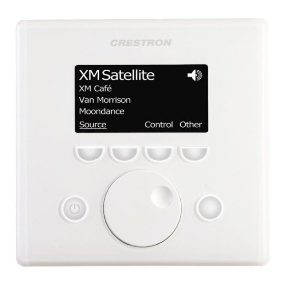
Page 11: Lc-1000, Ct-1000 & Apad
Cutout Dimensions & Mounting Options LC-1000, CT-1000 & APAD Pre-Construction Mounting Options for the LC-1000, CT-1000 & APAD Touchpanels PRE-CONSTRUCTION KITS Back Box Kit Pre-Construction Kit Mud Mount Kit Trim Mount Kit Post-Construction Mounting Options for the LC-1000, CT-1000 & APAD Touchpanels... -
Page 12: Tpmc-10-Dsw
Cutout for TPMC-10-DSW NOTE: For additional details, refer to the latest version of the TPMC-10-DSW Operations and Installation Guide (Doc. 6400), available from the Crestron website. Crestron Doc. 4926A Cutout Dimensions & Mounting Options Cutout Dimensions & Mounting Options ®... -
Page 13: Tps-12L & Tps-12G-Qm-L
POST-CONSTRUCTION KITS Wall Mount Mud Kit Wall/Lectern Mount Trim Kit Rack-Mount Kit TPS-12L & TPS-12G-QM-L Cutout Dimensions Back Box BB-12L Dimensions Cutout Dimensions & Mounting Options Crestron MODEL NUMBER BB-12L PMK-12L MMK-12L TMK-12L MODEL NUMBER WMKM-12L WMKT-12L RMK-12L Crestron Doc. 4926A... -
Page 14: Tps-15L, Tps-15G-Qm-L, Tpmc-15-Ch-L & Tpmc-15-Qm-L
Post-Construction Mounting Options for the TPS-15 and TPS-15G-QM-L Touchpanels POST-CONSTRUCTION KITS Wall/Lectern Mount Trim Kit Wall Mount Kit with Mud Ring Rack-Mount Kit TPS-15L, TPS-15G-QM-L, TPMC-15-CH-L & TPMC-15-QM-L Cutout Dimensions Back Box BB-15L Dimensions Crestron Doc. 4926A Cutout Dimensions & Mounting Options MODEL NUMBER BB-15L PMK-15L MMK-15L TMK-15L... -
Page 15: Tps-17L, Tpmc-17-Ch-L, & Tpmc-17-Qm-L
Post-Construction Mounting Options for the TPS-17L Touchpanels POST-CONSTRUCTION KITS Wall/Lectern Mount Trim Kit Rack-Mount Kit TPS-17L, TPMC-17-CH-L, & TPMC-17-QM-L Cutout Dimensions Back Box BB-17L Dimensions Cutout Dimensions & Mounting Options Crestron MODEL NUMBER BB-17L PMK-17L MMK-17L TMK-17L MODEL NUMBER WMKT-17L RMK-17L Crestron Doc. 4926A... -
Page 16: Tps-2000L
Water Resistant Cover TPS-2000L Cutout Dimensions NOTE: For additional TPS-2000L mounting information, refer to the latest version of the Crestron Touchpanel Mounting Quick Start, Doc. 6140, available from the Crestron website (www.crestron.com). Back Box BB-2000L and Mounting Plate Dimensions Crestron Doc. 4926A Cutout Dimensions &... -
Page 17: Tps-3100L
WARNING: The TPS-3100L is physically different from the discontinued TPS-3000L and the mounting options and cutout dimensions are not interchangeable. NOTE: For additional TPS-3100 mounting information, refer to the latest version of the Crestron Touchpanel Mounting Quick Start, Doc. 6140, available from the Crestron website (www.crestron.com). Crestron... -
Page 18: Tps-4000L
Architectural Faceplates Rack Mount Kit TPS-4000L Cutout Dimensions NOTE: For additional TPS-4000L mounting information, refer to the latest version of the Crestron Touchpanel Mounting Quick Start, Doc. 6140, available from the Crestron website (www.crestron.com). Back Box BB-4000L Dimensions Crestron Doc. 4926A Cutout Dimensions &... -
Page 19: Tps-4500L, Tps-4500Lv & Tps-5000L
V3 =9.866 in (25.060 cm) V4 =0.179 in (0.455 cm) V5 =0.089 in (0.226 cm) Crestron MODEL NUMBER BB-5000L MODEL NUMBER TPS-FPAR5000L RMK-5000L RADIUS MEASUREMENTS R1 =0.161 in (0.409 cm) typical R2 =0.312 in (0.792 cm) typical Crestron Doc. 4926A... - Page 20 Crestron Cutout Dimensions & Mounting Options Back Box BB-5000 Dimensions Crestron Doc. 4926A Cutout Dimensions & Mounting Options...
-
Page 21: Tps-6000L
Pre-Construction Mounting Options for the TPS-6000L Touchpanels PRE-CONSTRUCTION KITS Back Box Kit Post-Construction Mounting Options for the TPS-6000L Touchpanels POST-CONSTRUCTION KITS Architectural Faceplates Rack Mount Kit BB-6000 Cutout Dimensions Cutout Dimensions & Mounting Options Crestron MODEL NUMBER BB-6000L MODEL NUMBER TPS-FPAR6000L RMK-6000L Crestron Doc. 4926A... - Page 22 Crestron Cutout Dimensions & Mounting Options Back Box BB-6000L Dimensions Crestron Doc. 4926A Cutout Dimensions & Mounting Options...
-
Page 23: Tps-4L
Lectern/Wall Mounting Kit with Trim Ring Wall Mount Kit with Mud Ring TPS-4L Pre Construction Cutout Template Dimensions TPS-4L Post Construction Cutout Template Dimensions Cutout Dimensions & Mounting Options Crestron MODEL NUMBER BB-4L PMK-4L TMK-4L MMK-4L MODEL NUMBER WMKT-4L WMKM-4L Crestron Doc. 4926A... -
Page 24: C2N-Ft-Tps4
Crestron Cutout Dimensions & Mounting Options C2N-FT-TPS4 Crestron Doc. 4926A Cutout Dimensions & Mounting Options... -
Page 25: Stx-1700Cw And Stx-1700Cxpw
Cutout Dimensions & Mounting Options STX-1700CW and STX-1700CXPW Back Box Enclosure BB-1700CW Physical Views and Dimensions Cutout Dimensions & Mounting Options Optional Mounting Devices DA-1700CW Docking assembly, attaches to back box BB-1700CW Back Box Back box for wall mounting Crestron Crestron Doc. 4926A... -
Page 26: Thermostats, Temperature And Temperature/Humidity Sensors
Crestron Thermostats, Temperature and Temperature/Humidity Sensors CHV-TSTAT and CHV-THSTAT Thermostats are mounted to a single-gang electrical box, or directly to the wall using hollow wall anchors. Crestron Doc. 4926A Cutout Dimensions & Mounting Options Cutout Dimensions & Mounting Options... -
Page 27: Chv-Rts & Chv-Rths
CHV-RTS & CHV-RTHS CHV-RSS Crestron recommends that the sensor be placed inside a ½ inch Electrical Metallic Tubing (EMT) conduit. This allows future sensor replacement, if required. The radius of the bend at the wall should be approximately eight inches, to allow for removal and replacement of the sensor. -
Page 28: C2N-Rths
CHV-RSS Wood Floor Mounting C2N-RTHS NOTE: The C2N-RTHS is not to be used in conjunction with the CHV-TSTAT or the CHV-THSTAT. The C2N-RTHS is a Cresnet network device. Crestron Doc. 4926A Cutout Dimensions & Mounting Options Cutout Dimensions & Mounting Options... -
Page 29: Keypads
Be careful when cutting the hole, the spring clips on the keypad does not have provision for positioning adjustment. Also, ensure that there is a sufficient clearance area behind the mounting surface as shown on the template. Cutout Dimensions & Mounting Options Crestron Crestron Doc. 4926A... -
Page 30: Mediamanager Devices
(4006405 or 4006874) is included. Cutout Dimensions QM (4006405) NOTE: Before inserting the QM-FTCC in the mounting hole, ensure that all required cables have been installed. QM-FTCC-TPS4 Crestron Doc. 4926A Cutout Dimensions & Mounting Options QMI (4006874) Cutout Dimensions & Mounting Options... -
Page 31: Im-Ftcc-B
The following diagram illustrates the required opening size to accommodate the IM-FTCC-B. Use the supplied template to make the cutout. Cutout Dimensions NOTE: Before inserting the IM-FTCC-B in the mounting hole, ensure that all required cables have been installed. Cutout Dimensions & Mounting Options Crestron Crestron Doc. 4926A... -
Page 32: Im-Tcc
The IM-TCC is designed to mount to the underside of a horizontal surface, such as a desktop, lectern, or podium, in a cutout area. Bracket Dimensions Cutout Dimensions Cutaway View of Mounting Crestron Doc. 4926A Cutout Dimensions & Mounting Options Cutout Dimensions & Mounting Options... -
Page 33: C2N-Ftb
Cutout Dimensions & Mounting Options C2N-FTB The C2N-FTB-B and the C2N-FTB-BALUM are Crestron keypad devices that provide a stylish flush-mount tabletop interface and control solution. The fliptop compartment provides organized storage for a variety of pullout computer, communication, and A/V cables, which stow neatly out of sight within the fliptop compartment when not in use. -
Page 34: Lighting And Shade/Drape Control
NOTE: Four keyholes are located within the enclosure and should be used if surface mounting. CAEN-Series enclosures are required to install CLX-Series lighting modules. Crestron Doc. 4926A Cutout Dimensions & Mounting Options All measurements of length are in inches and weight is in pounds. -
Page 35: C2N-Sdc And C2N-Sdc-Dc
The C2N-SDC and C2N-SDC-DC may be mounted in a two-gang electrical box or a 4” x 4” (1900) electrical box. Ensure that you are using a box with sufficient depth (minimum 1 ½”) to accommodate the wires and connectors required. Cutout Dimensions & Mounting Options Crestron Crestron Doc. 4926A... -
Page 36: Cls-C6 And Cls-C6M
Crestron Cutout Dimensions & Mounting Options CLS-C6 and CLS-C6M The CLS-C6 and CLS-C6M mount in a standard 4-gang electrical box. Crestron Doc. 4926A Cutout Dimensions & Mounting Options... -
Page 37: Further Inquiries
For assistance in your local time zone, refer to the Crestron website (www.crestron.com) for a listing of Crestron worldwide offices. You can also log onto the online help section of the Crestron website to ask questions about Crestron products. First-time users will need to establish a user account to fully benefit from all available features. - Page 38 Crestron Electronics, Inc. Cutout Dimensions & Mounting Options 15 Volvo Drive Rockleigh, NJ 07647 Doc. 4926A Tel: 888.CRESTRON 3.06 Fax: 201.767.7576 Specifications subject to www.crestron.com change without notice.
Need help?
Do you have a question about the APAD and is the answer not in the manual?
Questions and answers