
Summary of Contents for Brasiltec SC1-3003
- Page 1 AC servo system Brasiltec Technical Manual Safety notification Indicates an error in use, it will leads to hazardous conditions and result in death or serious Dangerous injury.
- Page 2 While the motor is running, please do not touch the rotating parts.If not,it will lead to injury. When installed on the machine running, please put the motor may at any time in advance the state of emergency stop. Otherwise it will lead to injuries, mechanical damage.
- Page 3 Do not care, set up in the following conditions. Otherwise it will cause fire, electric shock or do damage to the machine. The place of direct sunlight when we use it, the environment temperature must higher than the place of custody and set the temperature condition.
- Page 4 Do not make the main circuit cables and input and output signal cables / encoder cables use the same tube, do not put their banding together. When wiring the main circuit cable input and output signal cables should leave 30 cm or more. ...
- Page 5 1.2 Driver and motor model reference Driver Matched motor specification Server driver specification Motor Maximum Maximum Maximum model (output flange(mm) rated power rated torque rated speed voltage / (kW) (Nm) (rev/min) current) SC1-3003 220V/2.8A 1.27 3000 SC1-3010 220V/3A 0.75 2.39 3000 SC1-3011 220V/4.4A 2500...
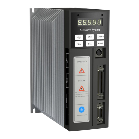
- Page 6 1.3 Driver appearance Power Indicator Servo ON indicator 5-digit LED display Cooling base, High temperature during work,don’t touch Key input 220V/50/60Hz Communication port L1 L2 when single phase L1 L2 L3 when three phase Signal terminal of input Motor UVW and output Regenerative resistor Protective grounding...
- Page 7 3) The relative humidity of the storage location must be in the range of 0% to 90% without condensation. 4) Avoid storage in environments containing corrosive gases and liquids. 5) It is best to store it properly on a shelf or countertop. 2.3 Installation environmental conditions The using temperature range of our driver is 0 degree to 55 degree.If the temperature exceeds 45 degree, please place it in a well-ventilated place.
- Page 8 Please install in strict accordance with the specified installation spacing to ensure good ventilation and heat dissipation. >100mm >50mm >50mm >50mm >100mm Chapter 3 Wiring 3.1 Servo system schematic Voltage Input and output terminals are connected to PLC and analog and pulse input...
- Page 9 3.2 Driver terminal and connection instructions Terminal symbol Name Fuction L1 L2 L3 Power terminal Three/single phase 220V to 240V 50/60Hz. (If R S T single phase connect L1 & L2) U V W Motor power line Connect with motor terminal P+ D C Regenerative...
- Page 10 3.4 Brake wiring In a vertical mechanism, when power off or the servo is enable OFF, the workpiece will fall due to gravity.So we need to use the servo motor with brake to avoid it’s slide down Parameter setting:P5-24 set 0084;P5-26 set 0000;then power off the driver and restart.If the workpiece is slightly down when enable OFF, increase P5-06 around 100ms or decrease the value of P5-08, and fine tune according to the situation;...
- Page 11 SO4-CO Output AGND Input AGND Input negative negative of analog of analog V-REF Speed T-REF Torque analog analog PULS- Pulse -10V Output +10V Output Input PULS +5V Pulse 5V 485 A 485 B Bus line communic Communicatio ation PULS Pulse24 +24V DIR- Direction...
- Page 12 Application mode: Position control (external pulse) P0-01 Parameter setting 6 Speed Control (External Pulse) P0-01 Parameter setting 7 Pulse command input wiring Host device side Servo driver +24V PULS PULS+24V 3.3K COM0 DIR+24V COM1 3.3K (3) Input and output signal circuit Optocoupler output circuit Host device Servo driver...
- Page 13 Relay input Host device side Servo driver +24V SI-COM 3.3K 3.6 CN2 encoder wiring and terminal description CN2 connector terminal arrangement is as follows (face to solder tab): Driver Name Driver Name Driver Name Driver Name interface interface interface interface 3.7 Communication port :...
- Page 14 Name Instruction RS485-A RS485-B RS232 receiving terminal RS232 sending terminal RS232 ground Downloader 3.8 MODBUS Protocol 1. Servo single register value setting: Sending Servo correct feedback Servo error feedback Hexadecimal Hexadecimal Hexadecimal Station No. Station No. Station No. Function Function Function code code...
- Page 15 Starting address Starting Error code address H Starting address Starting CRCH address L Number of Number of CRCL registers H registers H Number Number of registers L registers L Number of bytes CRCH Register value H CRCL Register value L Register value H Register value L CRCH...
- Page 16 CRCL Eg:Reading P0-01 data Use the default parameters of the servo the station number is 1 sending data: 01 03 00 01 00 01 CRCH CRCL Reading correct feedback data: 01 03 02 ** ** CRCH CRCL //** **data Reading error feedback data: 01 83 ** CRCH CRCL //** error code Chapter 4 Panel Display and Operation...
- Page 17 speed control:Synchronous speed detection Position control: end of positioning Speed control: torque limit Position control: approaching Speed control: rotation detection Position control: rotation detection Speed control: zero clamp Speed control: speed limit 4.2 basic state switching Running display status Parameter setting status Monitor display status...
- Page 18 In bb condition,select F4-00 to enter the factory default settings , suggesting rEt--, stay in a wait state , press Ent settings, wait for showing rEt-E, then power off and power on,now finish restore the factory defaults. J-OG mode In bb condition,choose F5-00,press shift to 0 blink,press Ent into show J-OG,press INC to show P motor running,press DEC to show N motor reverse running,short press motor jog,long press motor continuous running,jog speed setting:P3-04.
- Page 19 4.4 Brief description of code display code Display content In standby mode Servo OFF status (The motor is powered off) Running Servo enable(The motor is powered on) Prohibition of forward rotation P-OT OFF status. Please refer to "Overtravel Setting". Prohibition of reverse rotation N-OT OFF status.
- Page 20 4.6 Current check Function: Eliminate motor control instability or abnormal noise caused by inaccurate current sampling,whcih caused by hardware drift Method: Turn off the enable signal first. (External enable: Please disconnect the external signal; Internal power-on enable: set P0-01 to n.0101 and then power off and restart) ...
- Page 21 5.2 Servo power on Check before power-on UVW power line Power line L1L2 Encoder line Alarm or not Find alarm code Clear alarm factor Restart Display bb JOG tunning F5 Refer to f. in section 4.2 Chapter 6 Control Function 6.1Operating mode selection The driver has seven basic operating modes: speed, position and torque control, can through internal command control, external pulse signal and analog voltage control.
- Page 22 same time Selection signal switching through speed Speed mode Connect outside analog voltage signal (analog voltage) Adjust the voltage Proportional control of torque Proportion can be set Position mode Set the internal parameters of the driver (internal command) directly Control the number of rotation pulses and number of turns Trigger pulse transmission via CTRG signal Position mode...
- Page 23 n.8001 Power-on start (no external input signal required) Initial value:n. 01 01 ( H L) Control mode:all Unit:~ Setting range:~ Modify effective time:“●”Can be modified at any time, take effect by re-powered on Parameter function: H:00:Set the signal to always be invalid 01:Input positive signal from SI1 terminal 02:Input positive signal from SI2 terminal 03:Input positive signal from SI3 terminal...
- Page 24 6.2.3 Motor stop mode ◎P0-06 P0-06H:Overtravel shutdown method 0X0006 P0-06L:Servo OFF and alarm shutdown method Initial value:n. 02 02 ( H L) Control mode:All Unit:~ Setting range:0~3 Modify effective time:“●”Can be modified at any time, take effect by re-powered on Parameter function:H: 0~1:Inertial operation stops.
- Page 25 (2) Overtravel signal setting Parameter Signal name Meaning Modify Take effect P5-11.H /P-OT Input positive arbitrarily Re-power on signal from SI3 P5-12.L /N-OT Input positive arbitrarily Re-power on signal from SI4 1./P-OT, /N-OT signals can be assigned to other input interfaces via user parameters P5-11, P5-12. 2.
-
Page 26: Table Of Contents
H:00:Set the signal to always be invalid 01:Input positive signal from SI1 terminal 02:Input positive signal from SI2 terminal 03:Input positive signal from SI3 terminal 04:Input positive signal from SI4 terminal 05:Input positive signal from SI5 terminal 06:Input positive signal from SI6 terminal 07:Input positive signal from SI7 terminal 08:Input positive signal from SI8 terminal 80:Set the signal to always be active... -
Page 27: Electronic Gear Ratio (Molecular)
signal.Out/NEAR P5-04 With of positioning close 6.3.6 signal Pulse inhibit P5-16.H Inhibit signal of command 6.3.7 pulse/INHIBIT 6.3.1 Control mode Parameter Setting value Meaning Modify Take effect P0-01 Position Servo OFF immediate (External pulse) 6.3.2 Electronic gear ratio ◎P2-02 0X0202 Electronic gear ratio (molecular) ◎P2-03... -
Page 28: Filter Selection
In position control mode, the motor drives the screw to rotate, and motor rotates one circle(requires 10,000 pulse commands), and the workpiece moves one pitch (3mm). Then the motor moves: 3mm/10000=3um by receive one pulse. For easy control,to realize 1um per puls,we use electronic gear ratio. workpiece Motor Screw guide... -
Page 29: 6.3.4 Pulse Deviation Clear(/Clr
Control mode:6 Unit:1ms Setting range:0~100 Modify effective time:“●”Can be modified at any time, and take effect by power off and restart Parameter function: P2-04 difference between the first-order inertial filtering and smoothing filtering modes is as follows: first-order inertial filtering smoothing filtering 滤波前... -
Page 30: Positioning Completion Width
continue to accumulate. 6.3.5 Positioning completion signal(/COIN) Means the servo motor positioning is completed when on position control, and it is used when the command controller needs to confirm the positioning completion. Parameter Signal Factory Meaning Applicati Modi Take effect name setting on mode... - Page 31 Modify effective time:“○”can modify when servo OFF,and take effective by servo ON Parameter function:When the servo driver's pulse deviation value is lower than the set value of this parameter, output positioning proximity signal (/NEAR) . Please set this parameter to be larger than the positioning completion width.
-
Page 32: Positioning Proximity
√ P2-38 Third speed 0.1rpm √ P2-39 Third waiting time P2-40 Third instruction filtering time √ P2-41 Fourth pulse number -9999~+9999 √ P2-42 Fourth pulse number 10000 √ P2-43 Fourth speed 0.1rpm √ P2-44 Fourth waiting time P2-45 Fourth instruction filtering time P5-14.H /SPD-A P5-15.L... - Page 33 n.x□xx Waiting Waiting for P2-25 mode positioning complete Not waiting for positioning complete n.xx□x Step Change step when change the signal ON, it can mode be cycled Change step on signal rising edge, single step execution Start on the signal rising edge, execute in sequence Signal...
- Page 34 execute in sequence,no cycle 3:Trigger on the This setting can select any position by the /SPD-A/B/C/D signal, which is signal rising edge, triggered by the /CTRG signal. select the position segment by /SPD-A/B/C/D signal (3)Positioning mode n.xxx□ Meaning 0:Relativ Each position instruction is executed independently positioni 1:Absolu...
- Page 35 P5-03 Synchronous speed signal detection 6.5.6 width/V-CMP Torque limit P4-02 Forward torque limit 6.5.7 P4-03 Reverse torque limit 6.5.7 P0-07 T-REF distribution 6.5.7 P4-04 Forward external torque limit 6.5.7 P4-05 Reverse external torque limit 6.5.7 P5-13.L Forward external torque limit/P-CL 6.5.7 P5-13.H Reverse external torque limit/N-CL...
- Page 36 control device or the external circuit is shifted by a small amount (mV Unit). In this case, can use panel to do automatically adjust of command offset. Press the STA button to switch to F1-00; press the ENTER button to enter, and wait until the F-F appears, the adjustment is complete.
- Page 37 signal ◎P5-03 0X0503 Synchronous speed signal detection width Initial value: 10 Control mode:3,4,7 Unit:rpm Setting range:1~250 Modify effective time:“○”can modify when servo OFF,and take effective by servo ON.Take effect by restart Parameter function:The absolute value of the difference between the motor speed and the command speed.
- Page 38 Unit:1% Setting range:0~300 Modify effective time:“√“can modify at any time, immediately take effect. Parameter function:The external torque limit is used when mechanical operation or torque limit is required at a certain timing. For example, it is used for applications such as pressing stop motion or robot workpiece holding.
- Page 39 Control mode:3,4,7 Unit:1ms Setting range:0~65535 Modify effective time: “○”can modify when servo OFF, and take effective by servo ON Parameter function:Setting the appropriate acceleration time can prevent motor shake caused by excessive acceleration, but if the value set too big will affect the system response time. ◎P3-06 0X0306 Soft start deceleration time...
- Page 40 P5-14.L /SPD-D 6.6.3 P5-14.H /SPD-A 6.6.3 P5-15.L /SPD-B 6.6.3 Optional Parameter Keyword Parameter Name Proportional action P5-11.L Proportional action instruction/P-CON instruction P5-16.L Zero clamp/ZCLAMP P5-01 Zero clamp speed Synchronizing speed P5-21.H /V-CMP Synchronizing inspection signal output inspection P5-03 Synchronizing signal inspection width /V-CMP Torque limit P4-02...
- Page 41 ◎P3-02 0X0302 Internal setting speed 2 Initial value:0 Control mode:Speed control (internal speed setting selection) Unit:r/m(rpm) Setting range:-3000~3000 Modify effective time:“√“can modify at any time,will take effect immediately. Parameter function:Set value of speed 2 ◎P3-03 0X0303 Internal setting speed 3 Initial value:0 Control mode:Speed control (internal speed setting selection) Unit:r/m(rpm)...
- Page 42 P5-01 Zero clamp speed 6.5.5 Synchronizing P5-21.H /V-CMP Synchronizing 6.5.6 speed inspection inspection signal output P5-03 Synchronizing signal 6.5.6 inspection width /V-CMP Torque limit P4-02 Forward torque limit 6.5.7 P4-03 Reverse torque limit 6.5.7 P0-07 T-REF distribution 6.5.7 P4-04 Forward external torque limit 6.5.7 P4-05 Reverse external torque limit...
- Page 43 Modify effective time:“√“can modify at any time,will take effect immediately. Parameter function:When the command pulse frequency is relatively low, setting this parameter appropriately can reduce the fluctuation of the speed. 6.8 Torque (analog voltage) Basic Parameter Parameter Name Refer P0-01 Control method selection 6.8.1 P4-00...
- Page 44 Control mode:1,3,5,6,7 Unit:0.01ms Setting range:0~65535 Modify effective time:“○”can modify when servo OFF,and take effective by servo ON Parameter function: The torque command input through the primary delay filter to smooth the torque command. If the setting is too large, it will reduce responsiveness. 6.8.4 Speed limit ◎P4-07 0X0407...
- Page 45 Speed reaches the limit value output ◎P5-23 0X0516 H:/VLT Speed limit detection Initial value:n. 00 00 ( H L) Control mode:~ Unit:~ Setting range:~ Modify effective time:“●”can be modified at any time, and will take effect by power off and restart.
- Page 46 Alarm parameter :En-XX (Explain the meaning and solution of the alarm output code) Auxiliary parameter :FX-XX (System information check and recovery of factory setting and other functions) Symbol Description “○”can modify when servo OFF,and take effective by servo ON “●”can be modified at any time, and will take effect by power off and restart.
- Page 47 √ P0-14 Busbar alarm 220V 200~260 limit 380V 390~450 P1-XX Control parameter Modbus address:0100~01FF Parameter Function Unit Factory Setting range Effective time code default √ P1-00 Speed loop gain 1~5000 √ P1-01 Speed loop 0.1ms 1~50000 integral √ P1-02 Position loop gain 1~2000 P1-03 Parameter...
- Page 48 filter time P2-08 Parameter reserved P2-09 Parameter reserved √ P2-10 Command pulse input rate √ P2-11 Parameter reserved 0~65535 √ P2-12 Position loop max 0~65535 speed √ P2-13 Pulse positioning mark 0~50000 P2-14 Brake resistor type P2-15 Built-in braking resistor discharge cycle P2-16 Parameter reserved...
- Page 49 acceleration and deceleration time √ P2-36 Third stage pulse -9999~+9999 number √ P2-37 Third stage pulse 10000 number √ P2-38 Third stage speed 0.1rpm √ P2-39 Third stage waiting time ○ P2-40 Third stage -9999~+9999 acceleration and deceleration time √ P2-41 Forth stage pulse -9999~+9999...
- Page 50 ○ P3-08 Speed feedback 0.01ms 0~65535 filter time parameter ○ P3-09 Maximum speed 4000 0~5000 limit ○ P3-10 Dead zone voltage 0.01V 0~100 ○ P3-11 Speed S-type 0~65535 acceleration time √ P3-12 Brake delay when 0~65535 enabled P4-XX Torque Parameter Modbus address:0400~04FF Paramete Function Unit...
- Page 51 ○ P5-06 Servo OFF command 0~500 delay (brake command) ○ P5-07 Brake command output 0~5000 speed ○ P5-08 Brake command waiting 10~1000 time P5-09 Parameter reserved ● P5-10.L Input signal distribution 0、1 mode ● P5-10.H /SON Servo start signal 00~FF ●...
- Page 52 ● P5-21.H /VCMP Synchronous 00~FF speed detection output ● P5-22.L /TGON Rotation detection 00~FF output ● P5-22.H /S-RDY Ready 00~FF ● P5-23.L /CLT Torque limit 00~FF ● P5-23.H /VLT Speed limit 00~FF ● P5-24.L /BK Brake interlock 00~FF ● warning P5-24.H 00~FF /WARM...
- Page 53 F0-20 Rotor inertia 10 kg/m 0X0F14 ··· ··· ··· ··· F0-24 Motor model 0X0F17 F0-25 Input voltage and motor 0X0F18 flange F0-26 Software version 0X0F19 FX-XX FunctionParameter Parameter code Function Function finish Modbus address display F1-00 Correct V-ref zero point Inoperable F1-01 CorrectT-ref zero point...
- Page 54 The output torque of the servo motor is controlled by analog voltage torque command. It is often used in cooperate with the host computer for full-closed-loop torque control, such as tension control. (This mode cannot be used if the servo driver does not have an analog input interface.) 3:Speed control (internal speed setting selection) The servo driver can have 3 operating speeds.
- Page 55 ④ is Baud rate Initial value:6 Setting range 0 to 9 0:300 5:9600 1:600 6:19200 2:1200 7:38400 3:2400 8:57600 4:4800 9:115200 Note: After switching the direction, the ◎P0-05 0X0005 Direction of rotation signal received by the SERVO is reversed. Initial value:0 Control mode:1,2,3,4,5,6,7 Unit:~ Setting range:0,1...
- Page 56 Control mode:Speed mode Unit:~ Setting range:0~3 Modify effective time:“○”can modify when servo OFF,and take effective by servo ON Parameter function 0:Undefined. 1:Use T-REF as the external torque limit input. 2:Not defined. 3:When P-CL N-CL is ON, T-REF is used as the torque limit input. ◎P0-08 0X0008 V-REF distribution...
- Page 57 ◎P1-01 0X0101 Speed loop integration time Initial value:400 Control mode:3,4,5,6,7 Unit:0.1ms Setting range:1~5000 Modify effective time:“√“can modify at any time,will take effect immediately. Parameter function:The smaller the value of the speed loop integral time constant, the more high responsive of the speed control. ◎P1-02 0X0102 Position loop gain...
- Page 58 ◎P1-09 0X0109 Position loop front feedforward gain Initial value:0 Control mode:5,6 Unit:1% Setting range:1~100 Modify effective time:“√“can modify at any time,will take effect immediately. Parameter function:Setting unit here means 1% of the deviation pulse. In the case where a fast response of the position loop is required, the feedforward gain of the position loop can be appropriately increased, but if set too big,will cause overshoot of the speed loop.
- Page 59 Unit:~ Setting range:1~65535 Modify effective time:“○”can modify when servo OFF,and take effective by servo ON Parameter function:If the electronic gear ratio numerator is 1 and the denominator is 2, in the position internal command mode, the command pulse is set to 5000 (10000 pulses are required for the motor to make one revolution).
- Page 60 ◎P2-06 0X0206 Command pulse frequency at rated speed Initial value:5000 Control mode:7 Unit:100Hz Setting range:1~10000 Modify effective time:“√“can modify at any time,will take effect immediately. Parameter function:When P2-06 setting to 1000,the command pulse frequency corresponding to the rated speed is 100KHz. When P2-06 setting to 300,the command pulse frequency corresponding to the rated speed is 30KHz.
- Page 61 Modify effective time:“√“can modify at any time,will take effect immediately. Parameter function:Maximum speed limit for position control. ◎P2-13 0X020d Pulse positioning mark Initial value:0 Control mode: Unit:~ Setting range: Modify effective time:“√“can modify at any time,will take effect immediately. Parameter function: ◎P2-14 0X020e Parameter reserved...
- Page 62 Z origin trigger start mode: W origin stop mode setting: 0: Turn off the origin return function 0: After the origin detection is completed, the motor 1: When the power is turned on, the OPR decelerates and pulls back to the origin. Function is automatically executed.
- Page 63 P3-XX Speed parameter ◎P3-00 0X0300 Rated speed corresponds to analog Initial value:1000 Control mode:4 Unit:0.01V Setting range:150~3000 Modify effective time:“○”can modify when servo OFF,and take effective by servo ON Parameter function:Set the speed command voltage (V-REF) required to operate the servo motor at the rated speed Eg:P3-00=500 means the motor is running at rated speed when the analog input voltage is 5.00V.
- Page 64 Parameter function:Use when testing and no load is connected. ◎P3-05 0X0305 Soft start acceleration time Initial value:0 Control mode:3,4,7 Unit:1ms Setting range:0~65535 Modify effective time:“○”can modify when servo OFF,and take effective by servo ON Parameter function:Setting the appropriate acceleration time can prevent motor shake caused by excessive acceleration, but note that setting value too large will affect the system response time.
- Page 65 Parameter function:No matter what mode the motor is running, the running speed will not exceed this parameter setting value P4-XX Torque Parameter ◎P4-00 0X0400 The rated torque corresponds to the analog Initial value:1000 Control mode:2 Unit:0.01V Setting range:150~3000 Modify effective time:“○”can modify when servo OFF,and take effective by servo ON Parameter function:Set the speed command voltage (T-REF) required to operate the servo motor at the rated speed Eg:...
- Page 66 motor torque. The 300% rated torque is set as default, and the actual output maximum torque will vary depending on the model. ◎P4-04 0X0404 External positive torque limit Initial value:100 Control mode:Non-torque mode Unit:1% Setting range:0~300 Modify effective time:“√“can modify at any time,will take effect immediately. Parameter function:...
- Page 67 Unit:1% Setting range:-300~ 300 Modify effective time:“√“can modify at any time,will take effect immediately. Parameter function:Torque during torque control (internal setting). P5-XX Input and output signal settings ◎P5-00 0X0500 Positioning completion width Initial value:7 Control mode:5,6 Unit:1 pulse command Setting range:0~250 Modify effective time:“○”can modify when servo OFF,and take effective by servo ON Parameter function:When the pulse deviation value is lower than this parameter, output the positioning completion signal (/COIN).
- Page 68 Setting range:1~250 Modify effective time:“○”can modify when servo OFF,and take effective by servo restart Parameter function:The absolute value of the difference between the motor speed and the command speed. If the actual detected value is lower than the set value of P5-03, the /V-CMP synchronous speed signal is output.
- Page 69 The standard setting is that the servo turned OFF when /BK output (brake action) and when the servo OFF, the motor immediately enters no power state(no torque output). According to the mechanical configuration and the characteristics of the brake,there is a slight time difference between the output of the /BK signal and the brake action.
- Page 70 2) When the servo is turned OFF, the set time is exceeded of P5-08 value. In the "P5-07", even if the speed is set above the MAX speed, the actual speed value is only the MAX speed (P3-09). ◎P5-09 0X0509 Parameter reserved ◎P5-10 0X050a...
- Page 71 H:/P-OT Prohibit forward drive ◎P5-12 0X050c L:/N-OT Prohibit reverse drive is H:/ALM-RST Alarm clear Initial value:n. 05 04 ( H L) Control mode:All Unit:~ Setting range: Modify effective time:“●”can be modified at any time, and will take effect by power off and restart.
- Page 72 Unit:~ Setting range: Modify effective time:“●”can be modified at any time, and will take effect by power off and restart. Parameter function:The same as P5-10.H ◎P5-16 0X0510 L:/ZCLAMP Zero clamp H:/INHIBIT Command pulse prohibition Initial value:n. 00 00 ( H L)...
- Page 73 H:Parameter reserved Initial value:n. 00 00 ( H L) Control mode:Origin mode Unit:~ Setting range:~ Modify effective time:“●”can be modified at any time, and will take effect by power off and restart. Parameter function:The same as P5-10.L ◎P5-21 0X0514 L:/COIN Positioning finish H:/V-CMP Synchronous speed detection Initial value:n.
- Page 74 Initial value:n. 00 00 ( H L) Control mode:~ Unit:~ Setting range:~ Modify effective time:“●”can be modified at any time, and will take effect by power off and restart. Parameter function:The same as P5-21.L ◎P5-24 0X0517 L:/BK Brake H:/WARM Warning Initial value:n.
- Page 75 Un-03 Rotation angle (physical angle) 0.1° 0X703 Un-04 Rotation angle (electrical angle) 0.1° 0X704 Un-05 bus voltage 0X705 0.1℃ Un-06 Module temperature 0X706 Un-07 Input command pulse speed 0X707 Un-08 Offset command pulse value 0X708 Un-09 Offset command pulse value *10000 0X709 Un-10...