
Related Manuals for Brainlab VectorVision


Summary of Contents for Brainlab VectorVision
- Page 1 VECTORVISION ® System User Guide Revision 1.6 Copyright 2011, Brainlab AG Germany. All rights reserved.
-
Page 3: Table Of Contents
..............25 System User Guide Rev. 1.6 VectorVision... - Page 4 ................55 VECTORVISION SKY System User Guide Rev. 1.6 VectorVision...
- Page 5 ................72 Using VectorVision sky in an iMRI Environment .
- Page 6 ..............99 VectorVision sky Camera and Monitor Arm Joint .
-
Page 7: General Information
GENERAL INFORMATION GENERAL INFORMATION Chapter Overview 1.1.1 Contents Topics Covered Section Contact Data & Legal Information Page 8 Symbols Used in This Guide Page 10 Intended Use Page 11 Training & Documentation Page 12 System User Guide Rev. 1.6 VectorVision... -
Page 8: Contact Data & Legal Information
France & French-speaking Tel: +33-800-67-60-30 support_fr@brainlab.com regions Feedback Despite careful review, this manual may contain errors. Please contact us at igs.manuals@brainlab.com if you have suggestions as to how we can improve this manual. Manufacturer Brainlab AG Olof-Palme-Str. 9 81829 Munich Germany System User Guide Rev. -
Page 9: Legal Information
Brainlab AG in Germany and/or the US. Trademarks CE Label • The CE label shows that the Brainlab product complies with the essential re- quirements of Medical Device Directive (MDD). • According to MDD, Council Device Directive 93/42/EEC, classification of the Brainlab product is defined in the corresponding Software User Guide. -
Page 10: Symbols
Such problems include device malfunctions, device failure, damage to device or damage to property. Notes NOTE: Notes are formatted in italic type and indicate additional useful hints. System User Guide Rev. 1.6 VectorVision... -
Page 11: Intended Use
MR Conditional: The number shown on each label specifies the MR environment in which the device can be used with caution Plausibility Review Before patient treatment, review the plausibility of all information input to and output from the system. System User Guide Rev. 1.6 VectorVision... -
Page 12: Training & Documentation
• Simulate a sufficient number of complete procedures on sawbones and/or cadavers. • Use the system in operations where computed-aided navigation may be desirable but not essential. A Brainlab representative must be present at such operations to provide guidance where necessary. -
Page 13: Documentation
Quick Reference Guides are available for most software applications and for some complex instru- Guides ments. They provide condensed information on using the software or hardware, and are intended as a supplement to the User Guides. NOTE: Quick Reference Guides do not replace reading the User Guides. System User Guide Rev. 1.6 VectorVision... - Page 14 Training & Documentation System User Guide Rev. 1.6 VectorVision...
-
Page 15: Before You Begin
BEFORE YOU BEGIN BEFORE YOU BEGIN Chapter Overview 2.1.1 Contents Topics Covered Section Handling the System Correctly Page 16 Malfunctions & Return Instructions Page 18 System User Guide Rev. 1.6 VectorVision... -
Page 16: Correct Handling
The system is delivered pre-installed and can be used immediately. All system components are suitable for continuous operation. Only individuals trained by Brainlab may use the system in a clinical environment. Ventilation Do not block or cover ventilation slots on system base or housing, for example, with drapes. - Page 17 IEC 60601-1-1. If in doubt, consult the technical service department or Brainlab support.
-
Page 18: Malfunctions & Return Instructions
• Liquids leak from system • Smoke is emitted by system How to Respond to Damage or Failure Steps Turn off system. Unplug system from wall outlet. (Unplug VectorVision sky at 19” rack.) Contact Brainlab support. System User Guide Rev. 1.6 VectorVision... -
Page 19: Return Instructions
BEFORE YOU BEGIN 2.3.2 Return Instructions Removing Only remove defective components if instructed by Brainlab support. Components How to Return Components Steps Protect the component from further damage by wrapping it and packaging it in its original box or in a replacement box. - Page 20 Malfunctions & Return Instructions System User Guide Rev. 1.6 VectorVision...
-
Page 21: Vectorvision² Navigation Station
Topics Covered Section Components Page 22 Operating, Parking & Moving Positions Page 24 User Panel Page 30 Button Panel Page 33 Turning On/Off the System Page 34 UPS - Uninterruptible Power Supply Page 38 System User Guide Rev. 1.6 VectorVision... -
Page 22: Components
Components Components 3.2.1 Overview Front View Figure 1 Back View Figure 2 System User Guide Rev. 1.6 VectorVision... - Page 23 VECTORVISION² NAVIGATION STATION Components Component Brake Pedal Cable holder Handle Camera handle Touchscreen Monitor handles User panel Button panel System User Guide Rev. 1.6 VectorVision...
-
Page 24: Operating, Parking & Moving Positions
During transportation and storage Moving position When moving the system Ensure Appropriate Position To avoid damage to the system, other equipment or humans, only move, park or op- erate the system in appropriate position. System User Guide Rev. 1.6 VectorVision... -
Page 25: Parking & Moving Position
• Push the system using the handle. Safe Handling Unlock the brake before moving the system. Avoid vibrations and shocks during transportation and storage. Do not move, park or transport the system when the camera arm is open. System User Guide Rev. 1.6 VectorVision... -
Page 26: Operating Position
Unfold monitor arm and position touchscreen in desired position. Drape the camera handle. Drape the touchscreen. Plug in and turn on the system. NOTE: The software loads automatically. MR Environment The system is MR unsafe. System User Guide Rev. 1.6 VectorVision... -
Page 27: Securing The Cables
VECTORVISION² NAVIGATION STATION 3.3.4 Securing the Cables How to Secure Cables Figure 4 Step Wind the cables around cable holders Safe Handling Unplug and secure all cables before moving the system. Do not pull the cables. System User Guide Rev. 1.6 VectorVision... -
Page 28: Braking The System
To unlock the brake slide your foot under the pedal and bring the pedal into upper position To lock the brake push the pedal down with your foot until the snap mechanism has locked System User Guide Rev. 1.6 VectorVision... -
Page 29: Placing Protection Covers
Close the Velcro fastener for the camera arm to fasten the monitor protection cover to the camera arm. NOTE: Otherwise the camera arm may not remain in the transport position while the sys- tem is being moved. System User Guide Rev. 1.6 VectorVision... -
Page 30: User Panel
After all ports have been connected, snap cover shut by pulling it downwards. Make sure that all cables pass through cable slot Connecting Video Equipment Do not connect additional video equipment hardware to the original setting after cali- bration. System User Guide Rev. 1.6 VectorVision... -
Page 31: User Panel Ports
The appearance of the user panel varies depending on the configuration of your system. Example Figure 8 To inject images when using a microscope, plug the VGA cable of the VectorVision² into the VGA Image Injection Port connector of the microscope. - Page 32 Serial Port The Serial Port can be used for some microscopes which provide additional functions. To record the operation on a video, the VGA out port of the VectorVision² navigation station, con- VGA Out Port nect the television and/or an external monitor using an appropriate signal converter.
-
Page 33: Button Panel
• A circular control and display panel which has four LEDs, an On/Stand By button and an USB port • Located on the back of the curved arm Illustration Figure 10 Component On / Standby button Patientdata (USB port) Fault LED Battery Charge LED On Battery Power LED Power status LED System User Guide Rev. 1.6 VectorVision... -
Page 34: Turning On The System
Power Source Operate system using the source indicated on type plate. If you are unsure of type of power available, consult Brainlab support or your local power company. Waiting Period If system has been turned off, wait at least 15 seconds before turning it on again. Oth- erwise, high input current may trip the circuit breaker. -
Page 35: Turning Off The System
Power Supply To ensure complete disconnection from the power supply, unplug the power plug. The system is equipped with an uninterruptible power supply and is still powered after the main power cord has been disconnected. System User Guide Rev. 1.6 VectorVision... - Page 36 On / Standby button In case of an emergency shutdown, turn off system by pressing the On / Standby but- ton for 4 seconds and disconnect the system from the wall outlet. System User Guide Rev. 1.6 VectorVision...
-
Page 37: Using The Usb Port
Ensure that the USB flash drive is not visibly damaged or defective. Only use USB flash drives authorized by Brainlab. Keep the USB flash drive inserted until the active Brainlab application has been closed. Do not remove the USB flash drive while it is being used by an active applica- tion (e.g., when exiting the application, copying data or saving screenshots). -
Page 38: Ups - Uninterruptible Power Supply
(UPS). Meaning of Signals During a power failure, the UPS and the button panel emit specific signals to indicate that the system is operating from a limited internal source of power. System User Guide Rev. 1.6 VectorVision... -
Page 39: Vectorvision Compact Navigation Station
Chapter Overview 4.1.1 Contents Topics Covered Section Components Page 40 Operating, Parking & Moving Positions Page 42 User Panel, Potential Equalization & USB Port Page 48 Turning the System On and Off Page 53 System User Guide Rev. 1.6 VectorVision... -
Page 40: Components
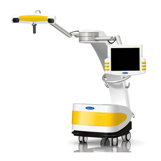
Components Components 4.2.1 Overview Front View Figure 11 System User Guide Rev. 1.6 VectorVision... - Page 41 VECTORVISION COMPACT NAVIGATION STATION Back View Figure 12 Components Component Camera handle Touchscreen Monitor handles Handle Cable holder User panel Brake Pedal System User Guide Rev. 1.6 VectorVision...
-
Page 42: Operating, Parking & Moving Positions
Moving position When moving the system Ensure Appropriate Position To avoid damage to the system, to other equipment or humans, always bring the sys- tem in the appropriate position before transporting, storing, or operating it. System User Guide Rev. 1.6 VectorVision... -
Page 43: Parking & Moving Positions
• Push the system using the handle. Safe Handling Unlock the brake before moving the system. Avoid vibrations and shocks during transportation and storage. Do not move, park or transport the system when the camera arm is open. System User Guide Rev. 1.6 VectorVision... -
Page 44: Operating Position
Unfold camera arm and position camera in desired position. Position touchscreen in desired position. Drape the camera handle. Drape the touchscreen. Plug in and turn on the system. NOTE: The software loads automatically. MR Environment The system is MR unsafe. System User Guide Rev. 1.6 VectorVision... -
Page 45: Securing The Cables
4.3.4 Securing the Cables How to Secure Cables Figure 14 Step Wind the cables around the cable holder Safe Handling Unplug and secure all cables before moving the system. Do not pull the cables. System User Guide Rev. 1.6 VectorVision... -
Page 46: Braking The System
To unlock the brake, slide your foot under the pedal and bring the pedal into upper position To lock the brake, push the pedal down with your foot until the snap mechanism has locked System User Guide Rev. 1.6 VectorVision... -
Page 47: Placing Protection Covers
Fasten the camera arm at the top of the camera protection cover using the velcro fasten- er for the camera arm NOTE: Otherwise the camera arm may not remain in the transport position while the nav- igation station is being moved. System User Guide Rev. 1.6 VectorVision... -
Page 48: User Panel, Potential Equalization & Usb Port
It also contains the reset button. Location The user panel is located at the back middle of the housing. Figure 17 Connecting Video Equipment Do not connect additional video equipment hardware to the original setting after cali- bration. System User Guide Rev. 1.6 VectorVision... -
Page 49: User Panel Ports
• Leica microscopes, connect the Microscope Leica port of the VectorVision compact to the corresponding port of the microscope using the supplied cable To record the operation on a video, the VGA out port of the VectorVision compact, connect the VGA Out Port television and/or an external monitor using an appropriate signal converter. - Page 50 If a proper system shutdown has not been performed, you can reset the computer using the Reset Reset Button button. Serial Port The Serial Port can be used for some microscopes which provide additional functions. System User Guide Rev. 1.6 VectorVision...
-
Page 51: Potential Equalization
• To reduce differences of potential which can occur during operation between medical electrical devices and the conductive parts of other objects Location The potential equalization plug is located at the back left of the cover. Illustration Figure 19 Potential equalization Unplugged Plugged System User Guide Rev. 1.6 VectorVision... -
Page 52: Usb Port
User Panel, Potential Equalization & USB Port 4.4.4 USB Port Purpose & Location You can load patient data to the VectorVision compact via a USB flash drive. The USB port is located at the front of the VectorVision compact. How to Use... -
Page 53: Turning The System On And Off
VECTORVISION COMPACT NAVIGATION STATION Turning the System On and Off 4.5.1 The I/O Switch Illustration Figure 21 Location The I/O switch is located at the back left of the housing. System User Guide Rev. 1.6 VectorVision... -
Page 54: Turning On
Power Source Operate system using the source indicated on type plate. If you are unsure of type of power available, consult Brainlab support or your local power company. Waiting Period If system has been turned off, wait at least 15 seconds before turning it on again. Oth- erwise, high input current may trip the circuit breaker. -
Page 55: Turning Off
To ensure complete disconnection from the power supply, unplug the power plug. Emergency Shutdown In case of an emergency shutdown, turn off the system by pressing the I/O switch and unplug the power supply cable. System User Guide Rev. 1.6 VectorVision... - Page 56 Turning the System On and Off System User Guide Rev. 1.6 VectorVision...
-
Page 57: Navigation Station
Operating Position Page 64 Parking Position Page 63 19” Rack, 19” Main Front Panel and UPS Page 66 Turning the System On and Off Page 70 Using VectorVision sky in an iMRI Environment Page 73 System User Guide Rev. 1.6 VectorVision... -
Page 58: Components
Components Components 5.2.1 Overview 19” Rack Figure 22 Component 19” Main Front Panel Front door Brake System User Guide Rev. 1.6 VectorVision... - Page 59 VECTORVISION SKY NAVIGATION STATION Wall Panels Figure 23 Component Wall panel, Rev. 1 Wall panel, Rev. 2 System User Guide Rev. 1.6 VectorVision...
- Page 60 VectorVision sky & VectorVision sky Vario Figure 24 Component Camera VectorVision sky Touchscreen VectorVision sky Vario OR lights NOTE: For information on 3rd-party ceiling systems and/or OR lights, refer to the 3rd-party manu- facturer’s manual. System User Guide Rev. 1.6 VectorVision...
-
Page 61: Guarantee
5.2.2 Guarantee Guarantee Brainlab guarantees that the VectorVision sky Vario system being installed by Brainlab support fol- lows the requirements of the IEC 60601-1-1 for Medical Electrical Systems. Expiration This guarantee expires if the system is changed by any other person than Brainlab support. -
Page 62: Operating And Parking Position Of Camera And Monitor
When moving the ceiling mounted arms, or when moving camera and monitor up and down, be careful not to hit individuals or surrounding medical equipment. Ensure Appropriate Position To avoid damage to the system, other equipment or humans, only store or operate the system in appropriate position. System User Guide Rev. 1.6 VectorVision... -
Page 63: Parking Position
Place protection covers on monitor g and camera f. Rotation Stoppers To avoid cable folds, the rotation angle of camera and touchscreen arm is limited to 330°. Do not try to move the arms further than allowed by the rotation stoppers. System User Guide Rev. 1.6 VectorVision... -
Page 64: Operating Position
Unfold camera arm and position camera in desired position. Unfold monitor arm and position touchscreen in desired position. Put sterile Camera Handle Sleeve on camera handle. Drape the touchscreen. Switch on main switch and UPS. NOTE: The software loads automatically. System User Guide Rev. 1.6 VectorVision... -
Page 65: Placing Protection Covers
Pull camera protection cover over camera. NOTE: The camera arm and/or the monitor arm might be pushed slightly downwards due to the additional weight of the protection covers. System User Guide Rev. 1.6 VectorVision... -
Page 66: 19" Rack, 19" Main Front Panel And Ups
• Insert or remove data media (CD-ROM, USB flash drive, ZIP disk) Back Door Only Brainlab support specialists are allowed to open the back door of the 19” rack. Do not open the back door of the 19” rack. Risk of electrical shock! - Page 67 Brake Figure 30 Ensure that the brake is locked at all times. The brake pedals must be pushed down. Only Brainlab support specialists are allowed to unlock the brake and move the 19” rack. System User Guide Rev. 1.6 VectorVision...
-
Page 68: 19'' Main Front Panel
50 Hz PAL or 60 Hz NTSC composite signal. Directly linked to the video source If a proper system shutdown has not been performed, you can reset the computer using the Reset Reset Button button. System User Guide Rev. 1.6 VectorVision... -
Page 69: Ups - Uninterruptible Power Supply
The alarm also sounds a “low battery tone” to warn you of an impending shutdown due to depleted battery power. UPS User Manual For detailed information about the UPS installed in your system see the user manual of the UPS. System User Guide Rev. 1.6 VectorVision... -
Page 70: Turning The System On And Off
Button, Example Figure 32 I/O Switch Figure 33 Components Component Location in 19” rack Main switch 19” main front panel UPS power on button, example UPS front panel I/O switch 19” main front panel System User Guide Rev. 1.6 VectorVision... -
Page 71: Turning On
Abnormal Impacts Do not use the system after an abnormal impact, such as an earthquake or explosion. Because of the possibility of fundamental structural damage to the building, a new structural evaluation must be performed. System User Guide Rev. 1.6 VectorVision... -
Page 72: Turning Off
A system switch off after use is recommended. Some components may age more rap- idly if the system is continuously powered. These components may have to be re- placed more often than other system parts. System User Guide Rev. 1.6 VectorVision... -
Page 73: Using Vectorvision Sky In An Imri Environment
Using VectorVision sky in an iMRI Environment 5.6.1 MR Safety Authorization Only individuals trained by Brainlab personnel are allowed to use the system in an MR environment. Servicing Precautions The ceiling mounted components of VectorVision sky may contain ferromagnetic ma- terials. -
Page 74: Imri Setup
Using VectorVision sky in an iMRI Environment 5.6.2 iMRI Setup The below illustration shows a typical setup of VectorVision sky in an MR environment: Setup Figure 34 Component Rooms iMRI scanner 50 Gauss / 5 mT field line 5 Gauss / 0.5 mT field line... - Page 75 50 gauss line at any time. Stationary MR If VectorVision sky is used in combination with a stationary MR System, the optimum position with System respect to the MR scanner and OR table has been planned and implemented as follows: If the ex- tension arms and spring-loaded arms are fully extended and leveled horizontally towards the mag- net, no terminal device penetrates the 50 Gauss fringe field zone.
-
Page 76: Disclaimer
• Clinical compatibility of any non-Brainlab device, regardless of its origin, that is introduced into the MR environment • Assessment of the proper clinical function of any device that was not manufactured by Brainlab. The manufacturer of the device and/or clinical engineering must make arrangements to test their device in the MR environment. -
Page 77: Operating Touchscreen & Camera
OPERATING TOUCHSCREEN & CAMERA OPERATING TOUCHSCREEN & CAMERA Chapter Overview 6.1.1 Contents Topics Covered Section Operating the Touchscreen Page 78 Operating the Camera Page 81 System User Guide Rev. 1.6 VectorVision... -
Page 78: Operating The Touchscreen
Lock the monitor by rotating fixation handle clockwise until you feel a slight resistance. Maintaining Position Do not hang any equipment on the monitor arm. System User Guide Rev. 1.6 VectorVision... - Page 79 A warning on the monitor arm alerts you to keep your fingers away from the center joint of the mon- itor arm: Figure 37 To prevent bruising, do not touch the center joint of the monitor arm with your fingers when the monitor arm is being moved. System User Guide Rev. 1.6 VectorVision...
-
Page 80: Selecting Buttons Or Functions
Do not touch the touchscreen using sharp tools. Diagnostic Use The touchscreen monitor does not comply with DIN EN 6868 and it is not intended for diagnostic use. Video images are not suitable for diagnostic use, as they may appear distorted. System User Guide Rev. 1.6 VectorVision... -
Page 81: Operating The Camera
Move the camera into the desired position so that the operating field is in the center of the camera field of view. Release the release button to set the new position. System User Guide Rev. 1.6 VectorVision... - Page 82 The following warning label is attached to the camera arm: Figure 40 To prevent bruising, do not touch the center joint of the camera arm with your fingers when the camera arm is being moved. System User Guide Rev. 1.6 VectorVision...
-
Page 83: Camera Field Of View
To ensure optimum accuracy, the tracking sensor requires a warm-up period at room temperature of approximately 20 minutes. Ensure that all highly reflective items or sources of light do not obstruct the camera’s view. Artifacts caused by reflections can reduce accuracy, especially during registra- tion. System User Guide Rev. 1.6 VectorVision... - Page 84 Operating the Camera System User Guide Rev. 1.6 VectorVision...
-
Page 85: Drapes
DRAPES DRAPES Chapter Overview 7.1.1 Contents Topics Covered Section Touchscreen Drape Page 86 Camera Handle Drape Page 89 System User Guide Rev. 1.6 VectorVision... -
Page 86: Touchscreen Drape
Sterile Field Maintaining the sterile field can only be guaranteed by using the Brainlab Touch- screen Drape. Using other drapes may cause monitor to malfunction. Carefully drape touchscreen. The drape maintains the surgeon's sterile field and pro- vides a sterile barrier between patient and touchscreen. -
Page 87: Draping The Touchscreen
DRAPES 7.2.2 Draping the Touchscreen Putting Drape on Figure 42 Sticking Tab Figure 43 Fastening Elastic Band Figure 44 System User Guide Rev. 1.6 VectorVision... - Page 88 Fasten drape using tie Verify that drape sits securely on touchscreen. Operating Draped Touchscreen Do not touch drape with sharp tools. To keep sterile field, only touch touchscreen and monitor housing where covered by drape. System User Guide Rev. 1.6 VectorVision...
-
Page 89: Camera Handle Drape
DRAPES Camera Handle Drape 7.3.1 Introduction The VectorVision² and VectorVision compact camera handle is draped using the sterile Light Purpose Handle Cover Large provided by Brainlab. Thus you can intraoperatively position the camera without compromising the sterile field. The Light Handle Cover Large is delivered sterile. Ensure that the packaging does not have any Packaging holes or tears. -
Page 90: Draping The Camera Handle
Verifying the Drape Verify that drape sits securely on camera handle and can only be removed by pushing release button. Verify that there is no gap between plastic foil and the plastic ring of the drape. System User Guide Rev. 1.6 VectorVision... - Page 91 DRAPES Operating Draped Camera Handle To maintain sterile field only touch camera handle where covered by drape. Do not touch camera above the plastic ring. System User Guide Rev. 1.6 VectorVision...
-
Page 92: Camera Handle Sleeve
Camera Handle Sleeve Camera Handle Sleeve 7.4.1 Introduction The sterile Camera Handle Sleeve is placed on the VectorVision sky camera handle so that the Purpose camera can be positioned intraoperatively without compromising the sterile field. MR Safety The Camera Handle Sleeve is MR unsafe. -
Page 93: Placing The Camera Handle Sleeve
To remove Camera Handle Sleeve from camera handle, push release button Verifying Camera Handle Sleeve Verify that the Camera Handle Sleeve has snapped in properly and cannot be released without pushing the release button. System User Guide Rev. 1.6 VectorVision... - Page 94 Camera Handle Sleeve System User Guide Rev. 1.6 VectorVision...
-
Page 95: Cleaning
VectorVision² and VectorVision compact Bases Page 97 VectorVision sky 19” Rack Page 98 VectorVision sky Wall Panel Page 99 VectorVision sky Camera and Monitor Arm Joint Page 100 VectorVision Monitor Page 101 VectorVision Camera Page 102 System User Guide Rev. 1.6 VectorVision... -
Page 96: General Instructions
No Sterilization Do not sterilize VectorVision components. No Liquids Ensure that liquid does not enter the VectorVision components, as this could damage the component and/or the electronics. Camera Handle The reprocessing of the camera handle sleeve is described in the Cleaning, Disinfection & Steril- Sleeve ization Guide. -
Page 97: Vectorvision Components
Do Not Use • Acid solvents • Caustic solvents with pH value higher than 9.5 To prevent damage to the device, only use approved solutions. System User Guide Rev. 1.6 VectorVision... -
Page 98: Vectorvision Sky 19" Rack
If particularly dirty, use a cloth that has been moistened in mild domestic detergent and then carefully wrung out. Do Not Use • Acid solvents • Caustic solvents with pH value higher than 9.5 • Alcohol To prevent damage to the device, only use approved solutions. System User Guide Rev. 1.6 VectorVision... -
Page 99: Vectorvision Sky Wall Panel
If required, add a mild detergent solution (pH4 - pH9). Do Not Use • Acid solvents • Caustic solvents with pH value higher than 9.5 • Alcohol To prevent damage to the device, only use approved solutions. System User Guide Rev. 1.6 VectorVision... -
Page 100: Vectorvision Sky Camera And Monitor Arm Joint
VectorVision Components 8.3.4 VectorVision sky Camera and Monitor Arm Joint Illustration Figure 51 How to Clean Steps Shut down system. Turn off system. Wipe camera arm joint using a soft cloth. The detergent temperature should be 25°C. Do Not Use •... -
Page 101: Vectorvision Monitor
Ensure that system is in parking position. • Wipe the monitor with a moist cloth. • Use an ammonia-based glass cleaner or an isopropyl alcohol based cleaner. Using other cleaning fluid may damage the touchscreen or the monitor housing. System User Guide Rev. 1.6 VectorVision... -
Page 102: Vectorvision Camera
• Wipe camera lenses with a camera cleaning cloth. • Use only commercial lens cleaner on camera lenses. Do Not Use • Alcohol • Chemicals To prevent damage to the device, only use approved solutions. System User Guide Rev. 1.6 VectorVision... -
Page 103: Monitor & Camera Protection Covers
How to Clean Step If necessary, clean surface of cover using a damp sponge and water or a mild cleaning or disin- fecting detergent. Do not wash, soak, iron, disinfect or sterilize protection covers. System User Guide Rev. 1.6 VectorVision... - Page 104 VectorVision Components System User Guide Rev. 1.6 VectorVision...
-
Page 105: Index
VectorVision sky ............manuals ............. VectorVision² ............monitor console monitor protection cover ........... VectorVision compact ........... VectorVision compact ..........VectorVision sky ..........VectorVision sky ............. VectorVision² ............. VectorVision² moving position ........... VectorVision compact ............. VectorVision² System User Guide Rev. 1.6 VectorVision... - Page 106 ............. VectorVision² ............console ..........return instructions ............drapes ........RF-shielded iMRI environment ......... draping camera handle ..........draping touchscreen ............I/O switch ............. interferences ..........locking the system ..........securing cables monitor cleaning System User Guide Rev. 1.6 VectorVision...
- Page 107 ............operating position ventilation .......... operating touchscreen ..........parking position ............... ports ..........positioning camera ......... positioning touchscreen ..............WEEE ............. power switch winding cables ..........protection covers ........... VectorVision compact ............reset button System User Guide Rev. 1.6 VectorVision...
- Page 108 INDEX ............. VectorVision² System User Guide Rev. 1.6 VectorVision...
- Page 110 Art-No: 60908-92EN *60908-92EN*...
Need help?
Do you have a question about the VectorVision and is the answer not in the manual?
Questions and answers