
Related Manuals for Beckhoff CX1500-M510


Summary of Contents for Beckhoff CX1500-M510
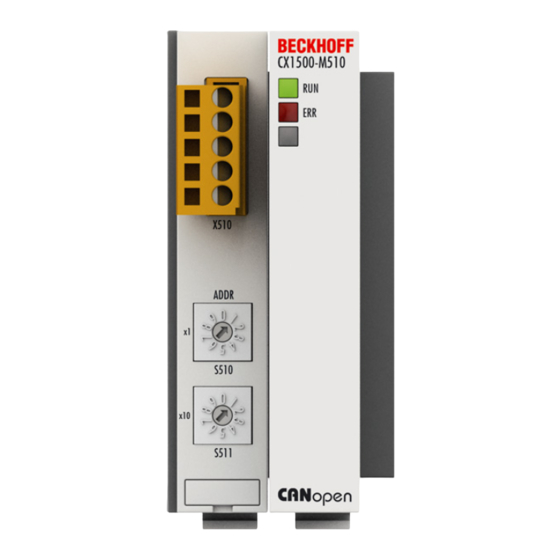
- Page 1 AS2000 Documentation | EN CX1500-M510, CX1500-B510 Blindtext Blindtext Blindtext CANopen - Bus interfaces for CX systems 2006/6/6 | Version: 1.0...
-
Page 3: Table Of Contents
Mechanical installation of the fieldbus connection............ 158 4.1.3 Connections........................ 159 Software Setup .......................... 163 4.2.1 Setup of CX1500-M510 for CANopen ................ 163 4.2.2 Startup of CX1500-B310 for CANopen................ 165 5 Error handling and diagnostics...................... 170 M510: LED diagnosis codes ...................... 170 B510: LED diagnosis codes ...................... 171 Diagnostics ............................ 171... - Page 4 Table of contents Certifications .......................... 179 Support and Service ........................ 179 Version: 1.0 CX1500-M510, CX1500-B510...
-
Page 5: Foreword
EP0851348, US6167425 with corresponding applications or registrations in various other countries. ® EtherCAT is registered trademark and patented technology, licensed by Beckhoff Automation GmbH, Germany Copyright © Beckhoff Automation GmbH & Co. KG, Germany. The reproduction, distribution and utilization of this document as well as the communication of its contents to others without express authorization are prohibited. -
Page 6: Safety Instructions
All the components are supplied in particular hardware and software configurations appropriate for the application. Modifications to hardware or software configurations other than those described in the documentation are not permitted, and nullify the liability of Beckhoff Automation GmbH & Co. KG. Personnel qualification This description is only intended for trained specialists in control, automation and drive engineering who are familiar with the applicable national standards. -
Page 7: Documentation Issue Status
Foreword Documentation Issue Status Version Changes revised version preliminary version CX1500-M510, CX1500-B510 Version: 1.0... -
Page 8: Product Overview
• Slave connection [} 10] The function is similar to the function of the Beckhoff PCI fieldbus cards. In opposite to them only one port is available in the modules for CX-Systems. The connection parameters will be set by using TwinCAT. The data transfer to the system is realized by a DPRAM via PC104 bus. -
Page 9: Technical Data Cx1500-M510
EN 61000-6-2 / EN 61000-6-4 Protection class IP 20 2.1.2 Connections CX1500-M510 / B510 The connection to the CANopen bus is realized by a 5 pin open style connector. The pin of the connector have the following definition:... -
Page 10: Adapter Ram Hardware Address Overview
The use of fieldbus master modules in a CX1000 / CX1020 system enables the utilization of all Beckhoff fieldbus components (e. g. Bus Coupler, Bus Terminal Controller, drive technology) as distributed control components for the assembly of complex systems. -
Page 11: Technical Data Cx1500-B510
The performance data of the CX fieldbus master modules are nearly identical to those of the Beckhoff PC fieldbus cards, except for the fact that the CX variants are always single-channel types. The number of slaves that can be connected is only limited by the respective bus system. -
Page 12: Adapter Ram Hardware Address Overview
(for more see note below). The order numbers for the modules are: Order number Alternative ISA-Address CX1500-B510-0001 D4000 CX1500-B510-0002 D6000 CX1500-B510-0003 D8000 CX1500-B510-0004 DA000 CX1500-B510-0005 DC000 Version: 1.0 CX1500-M510, CX1500-B510... -
Page 13: Canopen
The desired communication type is set by the Transmission Type [} 15] parameter. Device Profile The BECKHOFF CANopen devices support all types of I/O communication, and correspond to the device profile for digital and analog input/output modules (DS401 Version 1). For reasons of backwards compatibility, the default mapping was not adapted to the DS401 V2 profile version. -
Page 14: Canopen Baud Rate And Bit Timing
BECKHOFF website (http://www.beckhoff.com) for the parameterization of BECKHOFF CANopen devices using configuration tools from other manufacturers. Certification The BECKHOFF CANopen devices have a powerful implementation of the protocol, and are certified by the CAN in Automation Association (http://www.can-cia.org). 2.3.2... -
Page 15: Process Data Objects (Pdo)
29-bit versions remains limited to unusual applications. It is therefore also not supported by a Beckhoff's CANopen devices. The highest bit (bit 31) can be used to activate the process data object or to turn it off. - Page 16 TxPDO. PDO Communication Types: Outline CANopen offers a number of possible ways to transmit process data (see also: Notes on PDO Parameterization [} 104]).) Version: 1.0 CX1500-M510, CX1500-B510...
- Page 17 This does take longer, but does mean that the data is up-to-date. BECKHOFF use CAN controllers following the principle of Basic CAN.
- Page 18 (such as a change in input) having occurred. Transmission type 0 thus combines transmission for reasons that are event driven with a time for transmission (and, as far as possible, sampling) and processing given by the reception of "SYNC". Version: 1.0 CX1500-M510, CX1500-B510...
- Page 19 Although the BECKHOFF FC510x PC cards can parameterize the inhibit time on slave devices, they do not themselves support it. The transmitted PDOs become automatically spread out (transmit delay) as a result of the selected PLC cycle time - and there is little value in having the PLC run faster than the bus bandwidth permits.
- Page 20 The first location in the mapping table (sub-index 0) contains the number of mapped objects that are listed after it. The tables are located in the object directory at index 0x1600ff for the RxPDOs and at 0x1A00ff for the TxPDOs. Version: 1.0 CX1500-M510, CX1500-B510...
- Page 21 As a rule, the default mapping of the process data objects already satisfies the requirements. For special types of application the mapping can nevertheless be altered: the Beckhoff CANopen Bus Couplers, for instance, thus support variable mapping, in which the application objects (input and output data) can be freely allocated to the PDOs.
-
Page 22: Objects And Data
ManSpec. Manufacturer-specific error, specified more precisely in object 1003. Comm. Communication error (CAN overrun) Generic An error that is not more precisely specified has occurred (the flag is set at every error message) Error store Error store Version: 1.0 CX1500-M510, CX1500-B510... - Page 23 The bottom 11 bits of the 32 bit value contain the identifier (0x80=128 dec). Bit 30 indicates whether the device sends the SYNC telegram (1) or not (0). The CANopen I/O devices receive the SYNC telegram, and accordingly bit 30=0. For reasons of backwards compatibility, bit 31 has no significance. Sync Interval Sync Interval CX1500-M510, CX1500-B510 Version: 1.0...
- Page 24 1.5 times the communication cycle period that has been set - the planned SYNC interval can therefore be entered. The I/O update is carried out at the Beckhoff CANopen bus nodes immediately after reception of the SYNC telegram, provided the following conditions are satisfied: - Firmware status C0 or above (CANopen Version 4.01 or higher).
- Page 25 If a guarding telegram is not received within the life time, the node enters the error state. If the life time factor and/or guard time = 0, the node does not carry out any life guarding, but can itself be monitored by the master (node guarding). Guarding identifier Guarding identifier CX1500-M510, CX1500-B510 Version: 1.0...
- Page 26 • All guarding parameters • Limit values, delta values and interrupt enables for analog inputs Parameters directly stored in the terminals by way of register communication are immediately stored there in non-volatile form. Load default values Load default values Version: 1.0 CX1500-M510, CX1500-B510...
- Page 27 (1) the emergency telegram or not (0). Alternatively, the bus node's diagnostic function can also be switched off using the Device diagnostics bit in the K-Bus configuration (see object 0x4500). Consumer heartbeat time Consumer heartbeat time CX1500-M510, CX1500-B510 Version: 1.0...
- Page 28 As is usual in CANopen, the LSB is transferred first, followed by the MSB. Producer heartbeat time Producer heartbeat time Index Sub-index Name Type Attribute Mapping Default Meaning value 0x1017 Producer Unsigned16 rw Interval in heartbeat time between transmitted heartbeat telegrams Device identifier (identity object) Device identifier (identity object) Version: 1.0 CX1500-M510, CX1500-B510...
- Page 29 Unsigned32 ro Production Number date low word, high byte: calendar week (dec), low word, low byte: calendar year Product Product Code BK5120 0x11400 BK5110 0x113F6 LC5100 0x113EC IPwxyz-B510 0x2wxyz IL2301-B510 0x2008FD Server SDO parameters Server SDO parameters CX1500-M510, CX1500-B510 Version: 1.0...
- Page 30 Unsigned32 ro 0x0000058 COB-ID Server - 0 + Node- TxSDO >Client (Client -> Server) This is contained in the object directory for reasons of backwards compatibility. Communication parametersfor the 1st RxPDO for the 1st RxPDOCommunication parameters Version: 1.0 CX1500-M510, CX1500-B510...
- Page 31 PDO is permissible (0) or not (1). Changing the identifier (bits 0-10) is not allowed while the object exists (bit 31=0). Sub-index 2 contains the type of the transmission (see introduction to PDOs). Communication parametersfor the 2nd RxPDO for the 2nd RxPDOCommunication parameters CX1500-M510, CX1500-B510 Version: 1.0...
- Page 32 Present for Priority reasons of Group backwards compatibilit y, but not used. Event Unsigned16 rw Event- Timer Timer. Watchdog time defined for monitoring reception of the PDO. Communication parametersfor the 3rd RxPDO for the 3rd RxPDOCommunication parameters Version: 1.0 CX1500-M510, CX1500-B510...
- Page 33 Present for Priority reasons of Group backwards compatibilit y, but not used. Event Unsigned16 rw Event- Timer Timer. Watchdog time defined for monitoring reception of the PDO. Communication parametersfor the 4th RxPDO for the 4th RxPDOCommunication parameters CX1500-M510, CX1500-B510 Version: 1.0...
- Page 34 Present for Priority reasons of Group backwards compatibilit y, but not used. Event Unsigned16 rw Event- Timer Timer. Watchdog time defined for monitoring reception of the PDO. Communication parametersfor the 5th-16th RxPDOs for the 5th-16th RxPDOsCommunication parameters Version: 1.0 CX1500-M510, CX1500-B510...
- Page 35 Timer. Watchdog time defined for monitoring reception of the PDO. The number of RxPDOs for each bus node type can be found in the technical data. Mapping parametersfor the 1st RxPDO for the 1st RxPDOMapping parameters CX1500-M510, CX1500-B510 Version: 1.0...
- Page 36 4. Activate mapping (set sub-index 0 of the mapping entry to the correct number of mapped objects) 5. Create PDO (set bit 31 in the identifier entry (sub-index 1) of the communication parameters to 0) Mapping parametersfor the 2nd RxPDO for the 2nd RxPDOMapping parameters Version: 1.0 CX1500-M510, CX1500-B510...
- Page 37 Since the analog outputs are organised in words, the length of the PDO in bytes can be found directly at sub-index 0. A specific sequence must be observed in order to change the mapping (see object index 0x1600). Mapping parametersfor the 3rd-16th RxPDO for the 3rd-16th RxPDOMapping parameters CX1500-M510, CX1500-B510 Version: 1.0...
- Page 38 NoteDS401 V2 specifies analog input and/or output data as the default mapping for PDOs 3+4. This corresponds to Beckhoff's default mapping when less than 65 digital inputs or outputs are present. In order to ensure backwards compatibility, the Beckhoff default mapping is retained - the mapping behaviour of the devices therefore corresponds to DS401 V1, where in all other respects they ac- cord with DS401 V2.
- Page 39 PDOs of the same type, while sub-index 5 contains the event timer. Sub-index 4 is retained for reasons of compatibility, but is not used. (See also the introduction to PDOs.) Communication parametersfor the 2nd TxPDO for the 2nd TxPDOCommunication parameters CX1500-M510, CX1500-B510 Version: 1.0...
- Page 40 (transmission type 255). Event-driven mode must first be activated (see object 0x6423), otherwise the inputs can only be interrogated (polled) by remote transmission request (RTR). Communication parametersfor the 3rd TxPDO for the 3rd TxPDOCommunication parameters Version: 1.0 CX1500-M510, CX1500-B510...
- Page 41 (transmission type 255). Event-driven mode must first be activated (see object 0x6423), otherwise the inputs can only be interrogated (polled) by remote transmission request (RTR). Communication parametersfor the 4th TxPDO for the 4th TxPDOCommunication parameters CX1500-M510, CX1500-B510 Version: 1.0...
- Page 42 (transmission type 255). Event-driven mode must first be activated (see object 0x6423), otherwise the inputs can only be interrogated (polled) by remote transmission request (RTR). Communication parametersfor the 5th-16th TxPDOs for the 5th-16th TxPDOsCommunication parameters Version: 1.0 CX1500-M510, CX1500-B510...
- Page 43 Inhibit Time Unsigned16 rw Repetition delay [value x 100 µs] Unsigned8 rw Present for Priority reasons of Group backwards compatibilit y, but not used. Event Unsigned16 rw Event- Timer Timer Mapping 1st TxPDO Mapping 1st TxPDO CX1500-M510, CX1500-B510 Version: 1.0...
- Page 44 Since the digital inputs are organised in bytes, the length of the PDO in bytes can be found directly at sub-index 0. A specific sequence must be observed in order to change the mapping (see object index 0x1600). Mapping 2nd TxPDO Mapping 2nd TxPDO Version: 1.0 CX1500-M510, CX1500-B510...
- Page 45 Since the analog inputs are organised in words, the length of the PDO in bytes can be found directly at sub-index 0. A specific sequence must be observed in order to change the mapping (see object index 0x1600). Mapping 3rd-16th TxPDO Mapping 3rd-16th TxPDO CX1500-M510, CX1500-B510 Version: 1.0...
- Page 46 NoteDS401 V2 specifies analog input and/or output data as the default mapping for PDOs 3+4. This corresponds to Beckhoff's default mapping when less than 65 digital inputs or outputs are present. In order to ensure backwards compatibility, the Beckhoff default mapping is retained - the mapping behavior of the devices therefore corresponds to DS401 V1, where in all other respects they accord with DS401 V2.
- Page 47 Meaning value 0x2700 Number of Unsigned8 ro Depending Number of elements on type and available 3- fittings byte special channels, outputs output Unsigned24 rww 0x000000 output block channel 0X80 output Unsigned24 rww 0x000000 output block channel CX1500-M510, CX1500-B510 Version: 1.0...
- Page 48 Meaning value 0x2A00 Number of Unsigned8 ro Depending Number of elements on type and available 5- fittings byte special channels, inputs input Unsigned40 ro 0x0000000 input block channel 0X40 input Unsigned40 ro 0x0000000 input block channel Version: 1.0 CX1500-M510, CX1500-B510...
- Page 49 6- fittings byte special channels, outputs output Unsigned48 rww 0x0000000 output block channel 0X40 output Unsigned48 rww 0x0000000 output block channel Example of special terminals with 6-byte output data (in the default setting): KL5051, KL5101, KL5111 CX1500-M510, CX1500-B510 Version: 1.0...
- Page 50 Access (bit 7) + table Register number High byte register value Low byte register value number (bits 6...0) [0..1] + [0...0x7F] [0...0xFF] [0...0xFF] [0...0xFF] As is usual in CANopen, the LSB is transferred first, followed by the MSB. Version: 1.0 CX1500-M510, CX1500-B510...
- Page 51 Step Table Register Value Corresponding SDO download value (0x4500/0) 99 45054 (0xAFFE) 0xE3 02 AF FE (0xE3=0x63(=99)+ 0x80) 1 (0x0001) 0xE3 01 00 01 257 (0x0101) 0xE3 00 01 01 CX1500-M510, CX1500-B510 Version: 1.0...
- Page 52 2 bit digital output terminal, e.g. KL2034, KL2612, KL2702 0x8401 4 bit digital input terminal, e.g. KL1104, KL1124, KL1194 0x8402 4 bit digital output terminal, e.g. KL2124, KL2134, KL2184 0x8403 4 bit digital input/output terminal, e.g. KL2212 Version: 1.0 CX1500-M510, CX1500-B510...
- Page 53 0: Stop the K-Bus cycles, watchdog in the terminals triggers, fault output values become active. The old output values are initially set during a restart. 1: Set outputs to 0, then stop the K-Bus cycles (default). 2: Outputs remain unchanged. CX1500-M510, CX1500-B510 Version: 1.0...
- Page 54 254 The 32 bit value is composed as follows: Access (bit 7) + channel Register number High byte register value Low byte register value number (bits 6...0) [0..1] + [0...0x7F] [0...0xFF] [0...0xFF] [0...0xFF] Version: 1.0 CX1500-M510, CX1500-B510...
- Page 55 Before the user registers in the Bus Terminal (register 32-xx, depending on terminal type or extension module) can be written to, it is first necessary for write protection to be removed. The following codeword is written for this purpose into register 31 of the channel concerned: CX1500-M510, CX1500-B510 Version: 1.0...
- Page 56 PDO2…11. PDOs that do not have process data (and which are thus superfluous in the present configuration) are not activated. NoteThis object can only be written in the pre-operational state! Version: 1.0 CX1500-M510, CX1500-B510...
- Page 57 > 64, otherwise identification overlaps can occur. In that case, the PDO identi- fiers must be set individually. For the sake of clarity, the default identifiers defined according to CANopen are also listed here: CX1500-M510, CX1500-B510 Version: 1.0...
- Page 58 Number of Unsigned8 ro Depending Number of elements on type and available fittings digital 8-bit input data blocks input Unsigned8 ro 0x00 input block channel 0XFE input Unsigned8 ro 0x00 input block channel Interrupt mask Interrupt mask Version: 1.0 CX1500-M510, CX1500-B510...
- Page 59 The interrupt mask for TxPDOs with analog input data is not evaluated if either limit values (0x6424, 0x6425) or the delta function (0x6426) have been activated for the inputs. This entry has been implemented in firmware C3 and above. CX1500-M510, CX1500-B510 Version: 1.0...
- Page 60 8 bytes of user data identifier 0x600+ 0x22 0x26 0x61 0x05 0xFF 0x00 0x00 0x00 node ID 11 bit 8 bytes of user data identifier 0x600+ 0x22 0x26 0x61 0x06 0x00 0xFF 0xFF 0xFF node ID Digital outputs Digital outputs Version: 1.0 CX1500-M510, CX1500-B510...
- Page 61 The analog signals are displayed left aligned. The representation in the process image is therefore independent of the actual resolution. Detailed information on the data format can be found at the relevant signal type. Event driven analog inputs Event driven analog inputs CX1500-M510, CX1500-B510 Version: 1.0...
- Page 62 Values different from 0 activate the upper limit value for this channel. A PDO is then transmitted if this limit value is exceeded. In addition, the event driven mode must be activated (object 0x6423). The data format corresponds to that of the analog inputs. Lower limit value analog inputs Lower limit value analog inputs Version: 1.0 CX1500-M510, CX1500-B510...
-
Page 63: Automatic Pdo Mapping
PDOs with process data in the following order: 1. Digital I/Os (if more than than 64 are existent) 2. 1-byte terminals for special functions 3. Analog I/Os CX1500-M510, CX1500-B510 Version: 1.0... - Page 64 • 78 digital inputs und 48 digital outputs • 6 analog inputs und 4 analog outputs • one KL5001 (SSI-Sensor Interface: by default 4 byte inputs ) • one KL6001 (serial interface: by default 4 byte inputs and 4 byte outputs) Version: 1.0 CX1500-M510, CX1500-B510...
-
Page 65: Can Identifier List
The list provided here should assist in identifying and assigning CANopen messages. All the identifiers allocated by the CANopen default identifier allocation are listed, as well as the manufacturer-specific default identifiers issued by BECKHOFF via object 0x5500 [} 22] (only to be used in networks with node addresses less than 64). - Page 66 0x601 - 0x63F [0x67F] 1537 - 1599 [1663] Guarding / Heartbeat/ Bootup 0x701 - 0x73F [0x77F] 1793 - 1855 [1919] Identifier List Identifiers marked with * are given manufacturer-specific assignments on the Bus Couplers after writing index 0x5500 Version: 1.0 CX1500-M510, CX1500-B510...
- Page 67 SDO Tx Nd.20 Nd.63 Nd.43 EMCY TxPDO3*, 1452 SDO Tx Nd.21 Nd.1 Nd.44 EMCY TxPDO3*, 1453 SDO Tx Nd.22 Nd.2 Nd.45 EMCY TxPDO3*, 1454 SDO Tx Nd.23 Nd.3 Nd.46 EMCY TxPDO3*, 1455 SDO Tx Nd.24 Nd.4 Nd.47 CX1500-M510, CX1500-B510 Version: 1.0...
- Page 68 Nd.46 Nd.26 *, Nd.6 EMCY TxPDO3*, 1479 TxPDO10 Nd.47 Nd.27 *, Nd.7 EMCY TxPDO3*, 1480 TxPDO10 Nd.48 Nd.28 *, Nd.8 EMCY TxPDO3*, 1481 TxPDO10 Nd.49 Nd.29 *, Nd.9 EMCY TxPDO3*, 1482 TxPDO10 Nd.50 Nd.30 *, Nd.10 Version: 1.0 CX1500-M510, CX1500-B510...
- Page 69 TxPDO1, TxPDO3*, 1505 TxPDO10 DI, Nd.10 Nd.53 *, Nd.33 TxPDO1, TxPDO3*, 1506 TxPDO10 DI, Nd.11 Nd.54 *, Nd.34 TxPDO1, TxPDO3*, 1507 TxPDO10 DI, Nd.12 Nd.55 *, Nd.35 TxPDO1, TxPDO3*, 1508 TxPDO10 DI, Nd.13 Nd.56 *, Nd.36 CX1500-M510, CX1500-B510 Version: 1.0...
- Page 70 TxPDO1, TxPDO8*, 1531 TxPDO10 DI, Nd.36 Nd.16 *, Nd.59 TxPDO1, TxPDO8*, 1532 TxPDO10 DI, Nd.37 Nd.17 *, Nd.60 TxPDO1, TxPDO8*, 1533 TxPDO10 DI, Nd.38 Nd.18 *, Nd.61 TxPDO1, TxPDO8*, 1534 TxPDO10 DI, Nd.39 Nd.19 *, Nd.62 Version: 1.0 CX1500-M510, CX1500-B510...
- Page 71 TxPDO8*, 1558 SDO Rx DI, Nd.62 Nd.42 Nd.22 TxPDO1, 1003 TxPDO8*, 1559 SDO Rx DI, Nd.63 Nd.43 Nd.23 TxPDO6*, 1004 TxPDO8*, 1560 SDO Rx Nd.1 Nd.44 Nd.24 TxPDO6*, 1005 TxPDO8*, 1561 SDO Rx Nd.2 Nd.45 Nd.25 CX1500-M510, CX1500-B510 Version: 1.0...
- Page 72 TxPDO6*, 1029 RxPDO3*, 1584 SDO Rx Nd.25 Nd.5 Nd.48 TxPDO6*, 1030 RxPDO3*, 1585 SDO Rx Nd.26 Nd.6 Nd.49 TxPDO6*, 1031 RxPDO3*, 1586 SDO Rx Nd.27 Nd.7 Nd.50 TxPDO6*, 1032 RxPDO3*, 1587 SDO Rx Nd.28 Nd.8 Nd.51 Version: 1.0 CX1500-M510, CX1500-B510...
- Page 73 TxPDO6*, 1055 RxPDO3*, 1611 RxPDO10 Nd.51 Nd.31 *, Nd.11 TxPDO6*, 1056 RxPDO3*, 1612 RxPDO10 Nd.52 Nd.32 *, Nd.12 TxPDO6*, 1057 RxPDO3*, 1613 RxPDO10 Nd.53 Nd.33 *, Nd.13 TxPDO6*, 1058 RxPDO3*, 1614 RxPDO10 Nd.54 Nd.34 *, Nd.14 CX1500-M510, CX1500-B510 Version: 1.0...
- Page 74 RxPDO10 DO, Nd.14 Nd.57 *, Nd.37 RxPDO1, 1082 RxPDO3*, 1638 RxPDO10 DO, Nd.15 Nd.58 *, Nd.38 RxPDO1, 1083 RxPDO3*, 1639 RxPDO10 DO, Nd.16 Nd.59 *, Nd.39 RxPDO1, 1084 RxPDO3*, 1640 RxPDO10 DO, Nd.17 Nd.60 *, Nd.40 Version: 1.0 CX1500-M510, CX1500-B510...
- Page 75 1108 RxPDO8*, 1663 RxPDO10 DO, Nd.40 Nd.20 *, Nd.63 RxPDO1, 1109 RxPDO8*, 1665 TxPDO5*, DO, Nd.41 Nd.21 Nd.1 RxPDO1, 1110 RxPDO8*, 1666 TxPDO5*, DO, Nd.42 Nd.22 Nd.2 RxPDO1, 1111 RxPDO8*, 1667 TxPDO5*, DO, Nd.43 Nd.23 Nd.3 CX1500-M510, CX1500-B510 Version: 1.0...
- Page 76 TxPDO5*, Nd.2 Nd.45 Nd.25 RxPDO6*, 1134 RxPDO8*, 1690 TxPDO5*, Nd.3 Nd.46 Nd.26 RxPDO6*, 1135 RxPDO8*, 1691 TxPDO5*, Nd.4 Nd.47 Nd.27 RxPDO6*, 1136 RxPDO8*, 1692 TxPDO5*, Nd.5 Nd.48 Nd.28 RxPDO6*, 1137 RxPDO8*, 1693 TxPDO5*, Nd.6 Nd.49 Nd.29 Version: 1.0 CX1500-M510, CX1500-B510...
- Page 77 TxPDO5*, Nd.28 Nd.8 Nd.51 RxPDO6*, 1161 TxPDO4*, 1716 TxPDO5*, Nd.29 Nd.9 Nd.52 RxPDO6*, 1162 TxPDO4*, 1717 TxPDO5*, Nd.30 Nd.10 Nd.53 RxPDO6*, 1163 TxPDO4*, 1718 TxPDO5*, Nd.31 Nd.11 Nd.54 RxPDO6*, 1164 TxPDO4*, 1719 TxPDO5*, Nd.32 Nd.12 Nd.55 CX1500-M510, CX1500-B510 Version: 1.0...
- Page 78 RxPDO6*, 1187 TxPDO4*, 1743 TxPDO11 Nd.55 Nd.35 *, Nd.15 RxPDO6*, 1188 TxPDO4*, 1744 TxPDO11 Nd.56 Nd.36 *, Nd.16 RxPDO6*, 1189 TxPDO4*, 1745 TxPDO11 Nd.57 Nd.37 *, Nd.17 RxPDO6*, 1190 TxPDO4*, 1746 TxPDO11 Nd.58 Nd.48 *, Nd.18 Version: 1.0 CX1500-M510, CX1500-B510...
- Page 79 TxPDO11 AI, Nd.18 Nd.61 *, Nd.41 TxPDO2, 1214 TxPDO4*, 1770 TxPDO11 AI, Nd.19 Nd.62 *, Nd.42 TxPDO2, 1215 TxPDO4*, 1771 TxPDO11 AI, Nd.20 Nd.63 *, Nd.43 TxPDO2, 1217 TxPDO9*, 1772 TxPDO11 AI, Nd.21 Nd.1 *, Nd.44 CX1500-M510, CX1500-B510 Version: 1.0...
- Page 80 TxPDO2, 1240 TxPDO9*, 1796 Guarding AI, Nd.44 Nd.24 Nd.4 TxPDO2, 1241 TxPDO9*, 1797 Guarding AI, Nd.45 Nd.25 Nd.5 TxPDO2, 1242 TxPDO9*, 1798 Guarding AI, Nd.46 Nd.26 Nd.6 TxPDO2, 1243 TxPDO9*, 1799 Guarding AI, Nd.47 Nd.27 Nd.7 Version: 1.0 CX1500-M510, CX1500-B510...
- Page 81 Guarding Nd.6 Nd.49 Nd.29 TxPDO7*, 1266 TxPDO9*, 1822 Guarding Nd.7 Nd.50 Nd.30 TxPDO7*, 1267 TxPDO9*, 1823 Guarding Nd.8 Nd.51 Nd.31 TxPDO7*, 1268 TxPDO9*, 1824 Guarding Nd.9 Nd.52 Nd.32 TxPDO7*, 1269 TxPDO9*, 1825 Guarding Nd.10 Nd.53 Nd.33 CX1500-M510, CX1500-B510 Version: 1.0...
- Page 82 Guarding Nd.32 Nd.12 Nd.55 TxPDO7*, 1293 RxPDO4*, 1848 Guarding Nd.33 Nd.13 Nd.56 TxPDO7*, 1294 RxPDO4*, 1849 Guarding Nd.34 Nd.14 Nd.57 TxPDO7*, 1295 RxPDO4*, 1850 Guarding Nd.35 Nd.15 Nd.58 TxPDO7*, 1296 RxPDO4*, 1851 Guarding Nd.36 Nd.16 Nd.59 Version: 1.0 CX1500-M510, CX1500-B510...
- Page 83 TxPDO7*, 1319 RxPDO4*, 1875 RxPDO11 Nd.59 Nd.39 *, Nd.19 TxPDO7*, 1320 RxPDO4*, 1876 RxPDO11 Nd.60 Nd.40 *, Nd.20 TxPDO7*, 1321 RxPDO4*, 1877 RxPDO11 Nd.61 Nd.41 *, Nd.21 TxPDO7*, 1322 RxPDO4*, 1878 RxPDO11 Nd.62 Nd.42 *, Nd.22 CX1500-M510, CX1500-B510 Version: 1.0...
- Page 84 RxPDO11 AO, Nd.22 Nd.2 *, Nd.45 RxPDO2, 1347 RxPDO9*, 1902 RxPDO11 AO, Nd.23 Nd.3 *, Nd.46 RxPDO2, 1348 RxPDO9*, 1903 RxPDO11 AO, Nd.24 Nd.4 *, Nd.47 RxPDO2, 1349 RxPDO9*, 1904 RxPDO11 AO, Nd.25 Nd.5 *, Nd.48 Version: 1.0 CX1500-M510, CX1500-B510...
- Page 85 RxPDO2, 1372 RxPDO9*, 1928 RxPDO5*, AO, Nd.48 Nd.28 Nd.8 RxPDO2, 1373 RxPDO9*, 1929 RxPDO5*, AO, Nd.49 Nd.29 Nd.9 RxPDO2, 1374 RxPDO9*, 1930 RxPDO5*, AO, Nd.50 Nd.30 Nd.10 RxPDO2, 1375 RxPDO9*, 1931 RxPDO5*, AO, Nd.51 Nd.31 Nd.11 CX1500-M510, CX1500-B510 Version: 1.0...
- Page 86 RxPDO5*, Nd.10 Nd.53 Nd.33 RxPDO7*, 1398 RxPDO9*, 1954 RxPDO5*, Nd.11 Nd.54 Nd.34 RxPDO7*, 1399 RxPDO9*, 1955 RxPDO5*, Nd.12 Nd.55 Nd.35 RxPDO7*, 1400 RxPDO9*, 1956 RxPDO5*, Nd.13 Nd.56 Nd.36 RxPDO7*, 1401 RxPDO9*, 1957 RxPDO5*, Nd.14 Nd.57 Nd.37 Version: 1.0 CX1500-M510, CX1500-B510...
- Page 87 RxPDO7*, 1425 SDO Tx 1980 RxPDO5*, Nd.37 Nd.17 Nd.60 RxPDO7*, 1426 SDO Tx 1981 RxPDO5*, Nd.38 Nd.18 Nd.61 RxPDO7*, 1427 SDO Tx 1982 RxPDO5*, Nd.39 Nd.19 Nd.62 RxPDO7*, 1428 SDO Tx 1983 RxPDO5*, Nd.40 Nd.20 Nd.63 CX1500-M510, CX1500-B510 Version: 1.0...
-
Page 88: Emergency Object
5 bytes. This is divided into a 2-byte bit field and a 3-byte parameter field: 11 bit 8 bytes of user data identifier 0x80 EReg Bit field 0: Bit field 1: EMCY Info 0 Info 1 (=128dec) Comm DevErr Trigger + node-ID Version: 1.0 CX1500-M510, CX1500-B510... - Page 89 Product overview Table 1: Key CX1500-M510, CX1500-B510 Version: 1.0...
- Page 90 0x80 CAN warning limit exceeded Bit field 1: DevErr Bit field device error: 0x01 Terminal error 0x02 K-Bus error / IP-Link error 0x03 0x04 EEPROM error 0x10 Unsupported terminal plugged in (BK5110, LC5100) 0x80 Altered HW configuration. Version: 1.0 CX1500-M510, CX1500-B510...
- Page 91 Os to the neighboring station) 0x0C Unsupported terminal plugged in (BK5110 or LC5100) Info 1: terminal number (1...64) 0x0E EEPROM error; an error occurred when saving the configuration in CX1500-M510, CX1500-B510 Version: 1.0 the EEPROM 0x0F K-Bus error Info 0: Error type:...
-
Page 92: Protocol Description
Only one CAN message is then required to start the module: Start_Remote_Node: Identifier 0, two data bytes: 0x01, 0x00. It switches the node into the Operational state. Network Status Network Status The states and the state transitions involved as CANopen boots up can be seen from the state diagram: Version: 1.0 CX1500-M510, CX1500-B510... - Page 93 0 applying to all nodes (broadcast). 11 bit 2 bytes of user data identifier 0x00 Node-ID The following table gives an overview of all the CANopen state transitions and the associated commands (command specifier in the NMT master telegram): CX1500-M510, CX1500-B510 Version: 1.0...
- Page 94 Finally, the boot-up message communicates the end of the initialization phase; the Bus Coupler signals that it can now be configured or started. Firmware BA Up to firmware status BA the emergency identifier was used for the boot up message. Version: 1.0 CX1500-M510, CX1500-B510...
- Page 95 If either the status or the toggle bit do not agree with that expected by the NMT master, or if there is no answer at all, the master assumes that there is a slave fault. Guarding procedure Protocol Protocol CX1500-M510, CX1500-B510 Version: 1.0...
- Page 96 The master also regularly transmits its heartbeat telegram, so that the slaves are also able to detect failure of the master. Version: 1.0 CX1500-M510, CX1500-B510...
- Page 97 The parameters for the receive PDOs are at index 0x1400 (RxPDO1) onwards. There can be up to 512 RxPDOs (ranging up to index 0x15FF). In the same way, the entries for the transmit PDOs are located from index 0x1800 (TxPDO1) to 0x19FF (TxPDO512). CX1500-M510, CX1500-B510 Version: 1.0...
- Page 98 29-bit versions remains limited to unusual applications. It is therefore also not supported by a Beckhoff's CANopen devices. The highest bit (bit 31) can be used to activate the process data object or to turn it off.
- Page 99 A short reaction time is achieved at the same time, since when an input value changes it is not necessary to wait for the next interrogation from a master. CX1500-M510, CX1500-B510 Version: 1.0...
- Page 100 This does take longer, but does mean that the data is up-to-date. BECKHOFF use CAN controllers following the principle of Basic CAN.
- Page 101 (without first requesting up-to-date input data), there are circumstances in which it is questionable whether the polled data is up-to-date. Transmission types 252 and 253 are for this reason not supported by the BECKHOFF PC cards. Asynchronous...
- Page 102 Although the BECKHOFF FC510x PC cards can parameterize the inhibit time on slave devices, they do not themselves support it. The transmitted PDOs become automatically spread out (transmit delay) as a result of the selected PLC cycle time - and there is little value in having the PLC run faster than the bus bandwidth permits.
- Page 103 Object directory address Number of digital input bytes Index 0x6000, sub-index 0 Number of digital output bytes Index 0x6200, sub-index 0 Number of analog inputs Index 0x6401, sub-index 0 Number of analog outputs Index 0x6411, sub-index 0 CX1500-M510, CX1500-B510 Version: 1.0...
- Page 104 As a rule, the default mapping of the process data objects already satisfies the requirements. For special types of application the mapping can nevertheless be altered: the Beckhoff CANopen Bus Couplers, for instance, thus support variable mapping, in which the application objects (input and output data) can be freely allocated to the PDOs.
- Page 105 The Beckhoff FC510x PC cards are capable of synchronizing the CANopen bus system with the cycles of the application program (PLC or NC).
- Page 106 The BECKHOFF FC510x PC cards indicate the bus loading via the System Manager. This variable can also be processed in the PLC, or can be displayed in the visualization system.
- Page 107 Parameters whose data type is Unsigned8 are transmitted in byte D0, parameters whose type is Unsigned16 use D0 and D1. The number of valid data bytes is coded as follows in the first CAN data byte (0x4x): Number of param- eter bytes First CAN data byte 0x4F 0x4B 0x47 0x43 CX1500-M510, CX1500-B510 Version: 1.0...
- Page 108 A download of data up to 4 bytes in length can therefore always be achieved in Beckhoff bus nodes with 22h in the first CAN data byte. Client -> Server, Download Response...
- Page 109 0x06 01 00 21 Function still active, try again later 0x05 04 00 40 General routing error 0x06 06 00 21 Error accessing BC table 0x06 09 00 10 General error communicating with terminal 0x05 04 00 47 Time-out communicating with terminal CX1500-M510, CX1500-B510 Version: 1.0...
- Page 110 For broadcast objects the node ID is set to 0. This gives rise to the following default identifiers: Broadcast objects Object Function Function code Resulting COB ID Object for communica- tion Parame- ter / mapping Boot-Up 0 0x00 - / - SYNC Synchronization 1 0x80 0x1005 [} 22] + 0x1006 [} 22] / - Version: 1.0 CX1500-M510, CX1500-B510...
- Page 111 0x1017 [} 22]) *) The Beckhoff Default Mapping [} 63] applies to PDO 3 + 4. In most configurations, PDOs 3 and 4 contain data related to analog inputs and outputs, but there can also be "excess" data from digital I/Os, or data from special terminals.
-
Page 112: Objekt Directory
PDOs and the data width of the corresponding object (see also the section dealing with PDO Mapping). The communication and mapping parameters for the transmit PDOs are located in the regions from 0x1800 to 0x180F and from 0x1A00 to 0x1A0F. Version: 1.0 CX1500-M510, CX1500-B510... - Page 113 Product overview Manufacturer-specific region This region contains entries that are specific to BECKHOFF, e.g.: • data objects for special terminals • objects for register communication providing access to all the Bus Couplers’ and Bus Terminals’ internal registers • objects for simplified configuration of the PDOs Standardized device profile region The standardized device profile region supports the device profile of CANopen DS-401, Version 1.
- Page 114 If there has not been an error since power up, then object 0x1003 only consists of sub-index 0 with a 0 entered into it. The error store is cleared by a reset or a power cycle. As is usual in CANopen, the LSB is transferred first, followed by the MSB. Sync Identifier Sync Identifier Version: 1.0 CX1500-M510, CX1500-B510...
- Page 115 1.5 times the communication cycle period that has been set - the planned SYNC interval can therefore be entered. The I/O update is carried out at the Beckhoff CANopen bus nodes immediately after reception of the SYNC telegram, provided the following conditions are satisfied: - Firmware status C0 or above (CANopen Version 4.01 or higher).
- Page 116 Index Sub-index Name Type Attribute Mapping Default Meaning value 0x100C Guard time Unsigned16 rw Interval [ms] between two guard telegrams. Is set by the NMT master or configuratio n tool. Life time factor Life time factor Version: 1.0 CX1500-M510, CX1500-B510...
- Page 117 • All PDO parameters (identifier, transmission type, inhibit time, mapping). NoteThe stored identifiers apply afterwards, not the default identifiers derived from the node ad- dresses. Changes to the DIP switch setting no longer affects the PDOs! • All SYNC parameters CX1500-M510, CX1500-B510 Version: 1.0...
- Page 118 (1) the emergency telegram or not (0). Alternatively, the bus node's diagnostic function can also be switched off using the Device diagnostics bit in the K-Bus configuration (see object 0x4500). Consumer heartbeat time Consumer heartbeat time Version: 1.0 CX1500-M510, CX1500-B510...
- Page 119 As is usual in CANopen, the LSB is transferred first, followed by the MSB. Producer heartbeat time Producer heartbeat time Index Sub-index Name Type Attribute Mapping Default Meaning value 0x1017 Producer Unsigned16 rw Interval in heartbeat time between transmitted heartbeat telegrams Device identifier (identity object) Device identifier (identity object) CX1500-M510, CX1500-B510 Version: 1.0...
- Page 120 Unsigned32 ro Production Number date low word, high byte: calendar week (dec), low word, low byte: calendar year Product Product Code BK5120 0x11400 BK5110 0x113F6 LC5100 0x113EC IPwxyz-B510 0x2wxyz IL2301-B510 0x2008FD Server SDO parameters Server SDO parameters Version: 1.0 CX1500-M510, CX1500-B510...
- Page 121 Unsigned32 ro 0x0000058 COB-ID Server - 0 + Node- TxSDO >Client (Client -> Server) This is contained in the object directory for reasons of backwards compatibility. Communication parametersfor the 1st RxPDO for the 1st RxPDOCommunication parameters CX1500-M510, CX1500-B510 Version: 1.0...
- Page 122 PDO is permissible (0) or not (1). Changing the identifier (bits 0-10) is not allowed while the object exists (bit 31=0). Sub-index 2 contains the type of the transmission (see introduction to PDOs). Communication parametersfor the 2nd RxPDO for the 2nd RxPDOCommunication parameters Version: 1.0 CX1500-M510, CX1500-B510...
- Page 123 Present for Priority reasons of Group backwards compatibilit y, but not used. Event Unsigned16 rw Event- Timer Timer. Watchdog time defined for monitoring reception of the PDO. Communication parametersfor the 3rd RxPDO for the 3rd RxPDOCommunication parameters CX1500-M510, CX1500-B510 Version: 1.0...
- Page 124 Present for Priority reasons of Group backwards compatibilit y, but not used. Event Unsigned16 rw Event- Timer Timer. Watchdog time defined for monitoring reception of the PDO. Communication parametersfor the 4th RxPDO for the 4th RxPDOCommunication parameters Version: 1.0 CX1500-M510, CX1500-B510...
- Page 125 Present for Priority reasons of Group backwards compatibilit y, but not used. Event Unsigned16 rw Event- Timer Timer. Watchdog time defined for monitoring reception of the PDO. Communication parametersfor the 5th-16th RxPDOs for the 5th-16th RxPDOsCommunication parameters CX1500-M510, CX1500-B510 Version: 1.0...
- Page 126 Timer. Watchdog time defined for monitoring reception of the PDO. The number of RxPDOs for each bus node type can be found in the technical data. Mapping parametersfor the 1st RxPDO for the 1st RxPDOMapping parameters Version: 1.0 CX1500-M510, CX1500-B510...
- Page 127 4. Activate mapping (set sub-index 0 of the mapping entry to the correct number of mapped objects) 5. Create PDO (set bit 31 in the identifier entry (sub-index 1) of the communication parameters to 0) Mapping parametersfor the 2nd RxPDO for the 2nd RxPDOMapping parameters CX1500-M510, CX1500-B510 Version: 1.0...
- Page 128 Since the analog outputs are organised in words, the length of the PDO in bytes can be found directly at sub-index 0. A specific sequence must be observed in order to change the mapping (see object index 0x1600). Mapping parametersfor the 3rd-16th RxPDO for the 3rd-16th RxPDOMapping parameters Version: 1.0 CX1500-M510, CX1500-B510...
- Page 129 NoteDS401 V2 specifies analog input and/or output data as the default mapping for PDOs 3+4. This corresponds to Beckhoff's default mapping when less than 65 digital inputs or outputs are present. In order to ensure backwards compatibility, the Beckhoff default mapping is retained - the mapping behaviour of the devices therefore corresponds to DS401 V1, where in all other respects they ac- cord with DS401 V2.
- Page 130 PDOs of the same type, while sub-index 5 contains the event timer. Sub-index 4 is retained for reasons of compatibility, but is not used. (See also the introduction to PDOs.) Communication parametersfor the 2nd TxPDO for the 2nd TxPDOCommunication parameters Version: 1.0 CX1500-M510, CX1500-B510...
- Page 131 (transmission type 255). Event-driven mode must first be activated (see object 0x6423), otherwise the inputs can only be interrogated (polled) by remote transmission request (RTR). Communication parametersfor the 3rd TxPDO for the 3rd TxPDOCommunication parameters CX1500-M510, CX1500-B510 Version: 1.0...
- Page 132 (transmission type 255). Event-driven mode must first be activated (see object 0x6423), otherwise the inputs can only be interrogated (polled) by remote transmission request (RTR). Communication parametersfor the 4th TxPDO for the 4th TxPDOCommunication parameters Version: 1.0 CX1500-M510, CX1500-B510...
- Page 133 (transmission type 255). Event-driven mode must first be activated (see object 0x6423), otherwise the inputs can only be interrogated (polled) by remote transmission request (RTR). Communication parametersfor the 5th-16th TxPDOs for the 5th-16th TxPDOsCommunication parameters CX1500-M510, CX1500-B510 Version: 1.0...
- Page 134 Inhibit Time Unsigned16 rw Repetition delay [value x 100 µs] Unsigned8 rw Present for Priority reasons of Group backwards compatibilit y, but not used. Event Unsigned16 rw Event- Timer Timer Mapping 1st TxPDO Mapping 1st TxPDO Version: 1.0 CX1500-M510, CX1500-B510...
- Page 135 Since the digital inputs are organised in bytes, the length of the PDO in bytes can be found directly at sub-index 0. A specific sequence must be observed in order to change the mapping (see object index 0x1600). Mapping 2nd TxPDO Mapping 2nd TxPDO CX1500-M510, CX1500-B510 Version: 1.0...
- Page 136 Since the analog inputs are organised in words, the length of the PDO in bytes can be found directly at sub-index 0. A specific sequence must be observed in order to change the mapping (see object index 0x1600). Mapping 3rd-16th TxPDO Mapping 3rd-16th TxPDO Version: 1.0 CX1500-M510, CX1500-B510...
- Page 137 NoteDS401 V2 specifies analog input and/or output data as the default mapping for PDOs 3+4. This corresponds to Beckhoff's default mapping when less than 65 digital inputs or outputs are present. In order to ensure backwards compatibility, the Beckhoff default mapping is retained - the mapping behavior of the devices therefore corresponds to DS401 V1, where in all other respects they accord with DS401 V2.
- Page 138 Meaning value 0x2700 Number of Unsigned8 ro Depending Number of elements on type and available 3- fittings byte special channels, outputs output Unsigned24 rww 0x000000 output block channel 0X80 output Unsigned24 rww 0x000000 output block channel Version: 1.0 CX1500-M510, CX1500-B510...
- Page 139 Meaning value 0x2A00 Number of Unsigned8 ro Depending Number of elements on type and available 5- fittings byte special channels, inputs input Unsigned40 ro 0x0000000 input block channel 0X40 input Unsigned40 ro 0x0000000 input block channel CX1500-M510, CX1500-B510 Version: 1.0...
- Page 140 6- fittings byte special channels, outputs output Unsigned48 rww 0x0000000 output block channel 0X40 output Unsigned48 rww 0x0000000 output block channel Example of special terminals with 6-byte output data (in the default setting): KL5051, KL5101, KL5111 Version: 1.0 CX1500-M510, CX1500-B510...
- Page 141 Access (bit 7) + table Register number High byte register value Low byte register value number (bits 6...0) [0..1] + [0...0x7F] [0...0xFF] [0...0xFF] [0...0xFF] As is usual in CANopen, the LSB is transferred first, followed by the MSB. CX1500-M510, CX1500-B510 Version: 1.0...
- Page 142 Step Table Register Value Corresponding SDO download value (0x4500/0) 99 45054 (0xAFFE) 0xE3 02 AF FE (0xE3=0x63(=99)+ 0x80) 1 (0x0001) 0xE3 01 00 01 257 (0x0101) 0xE3 00 01 01 Version: 1.0 CX1500-M510, CX1500-B510...
- Page 143 2 bit digital output terminal, e.g. KL2034, KL2612, KL2702 0x8401 4 bit digital input terminal, e.g. KL1104, KL1124, KL1194 0x8402 4 bit digital output terminal, e.g. KL2124, KL2134, KL2184 0x8403 4 bit digital input/output terminal, e.g. KL2212 CX1500-M510, CX1500-B510 Version: 1.0...
- Page 144 0: Stop the K-Bus cycles, watchdog in the terminals triggers, fault output values become active. The old output values are initially set during a restart. 1: Set outputs to 0, then stop the K-Bus cycles (default). 2: Outputs remain unchanged. Version: 1.0 CX1500-M510, CX1500-B510...
- Page 145 254 The 32 bit value is composed as follows: Access (bit 7) + channel Register number High byte register value Low byte register value number (bits 6...0) [0..1] + [0...0x7F] [0...0xFF] [0...0xFF] [0...0xFF] CX1500-M510, CX1500-B510 Version: 1.0...
- Page 146 Before the user registers in the Bus Terminal (register 32-xx, depending on terminal type or extension module) can be written to, it is first necessary for write protection to be removed. The following codeword is written for this purpose into register 31 of the channel concerned: Version: 1.0 CX1500-M510, CX1500-B510...
- Page 147 PDO2…11. PDOs that do not have process data (and which are thus superfluous in the present configuration) are not activated. NoteThis object can only be written in the pre-operational state! CX1500-M510, CX1500-B510 Version: 1.0...
- Page 148 > 64, otherwise identification overlaps can occur. In that case, the PDO identi- fiers must be set individually. For the sake of clarity, the default identifiers defined according to CANopen are also listed here: Version: 1.0 CX1500-M510, CX1500-B510...
- Page 149 Number of Unsigned8 ro Depending Number of elements on type and available fittings digital 8-bit input data blocks input Unsigned8 ro 0x00 input block channel 0XFE input Unsigned8 ro 0x00 input block channel Interrupt mask Interrupt mask CX1500-M510, CX1500-B510 Version: 1.0...
- Page 150 The interrupt mask for TxPDOs with analog input data is not evaluated if either limit values (0x6424, 0x6425) or the delta function (0x6426) have been activated for the inputs. This entry has been implemented in firmware C3 and above. Version: 1.0 CX1500-M510, CX1500-B510...
- Page 151 8 bytes of user data identifier 0x600+ 0x22 0x26 0x61 0x05 0xFF 0x00 0x00 0x00 node ID 11 bit 8 bytes of user data identifier 0x600+ 0x22 0x26 0x61 0x06 0x00 0xFF 0xFF 0xFF node ID Digital outputs Digital outputs CX1500-M510, CX1500-B510 Version: 1.0...
- Page 152 The analog signals are displayed left aligned. The representation in the process image is therefore independent of the actual resolution. Detailed information on the data format can be found at the relevant signal type. Event driven analog inputs Event driven analog inputs Version: 1.0 CX1500-M510, CX1500-B510...
- Page 153 Values different from 0 activate the upper limit value for this channel. A PDO is then transmitted if this limit value is exceeded. In addition, the event driven mode must be activated (object 0x6423). The data format corresponds to that of the analog inputs. Lower limit value analog inputs Lower limit value analog inputs CX1500-M510, CX1500-B510 Version: 1.0...
- Page 154 (object 0x6423). The data format corresponds to that of the analog inputs (delta value: can only have positive values). 2.3.9.3 Objects and Data of the BX5100/BC5150 Access to located flags Access to located flags Version: 1.0 CX1500-M510, CX1500-B510...
-
Page 155: Ads-Communication
The data is not associated with a watchdog, and therefore must not be used for outputs that would have to be switched off in the event of a fault. Index group Meaning Index offset (value range) 0xF020 Inputs 0...2047 0xF030 Outputs 0...2047 0x4020 Flags 0...4095 CX1500-M510, CX1500-B510 Version: 1.0... - Page 156 NoteNote when reading the register that the time out for the ADS block is set to a time longer than 1 second. NoteNote when writing to the registers that the password is set (see the documentation for the par- ticular Bus Terminal). Version: 1.0 CX1500-M510, CX1500-B510...
-
Page 157: Transport
4. Please keep the associated paperwork. It contains important information for handling the unit. 5. Check the contents for visible shipping damage. 6. If you notice any shipping damage or inconsistencies between the contents and your order, you should notify Beckhoff Service. NOTE Danger of damage to the unit! During transport in cold conditions, or if the unit is subjected to extreme temperature swings, condensation on and inside the unit must be avoided. -
Page 158: Assembly And Connecting
The overall width of the application is made up of the individual modules. With a height of 100 mm, the module dimensions exactly match those of the Beckhoff Bus Terminals. Together with the lowered connector surfaces, this means that it can be used in a standard terminal box with a height of 120 mm. -
Page 159: Connections
Since the CAN signals are represented on the bus as the difference between the two levels, the CAN leads are not very sensitive to incoming interference (EMI): Both leads are affected, so the interference has very little effect on the difference. CX1500-M510, CX1500-B510 Version: 1.0... - Page 160 In the case of the bit timing settings selected in the Bus Couplers it can be assumed that this is the case, provided the following drop line lengths are not exceeded: Version: 1.0 CX1500-M510, CX1500-B510...
- Page 161 Shorter drop line lengths must be maintained when passive distributors ("multiport taps"), such as the Beckhoff ZS5052-4500 Distributor Box. The following table indicates the maximum drop line lengths and the maximum length of the trunk line (without the drop lines):...
- Page 162 HF interference will be transmitted from the mounting rail to the screen of the bus cable. In that case the screen should not be attached to the couplers - it should nevertheless still be fully connected through. Notes related to checking the CAN wiring can be found in the Trouble Shooting section. Version: 1.0 CX1500-M510, CX1500-B510...
-
Page 163: Software Setup
Assembly and connecting Cable colors Cable colors Suggested method of using the Beckhoff CAN cable on Bus Terminal and Fieldbus Box: BK51x0 pin Fieldbus Box FC510x pin Function ZB5100 cable ZB5200 cable color color CAN Ground black/ (red) black CAN Low... - Page 164 (the mode should be operational) If two or more devices on the bus have the same node-id none is found. Change the node-id and scan again. If the scan is complete the founded boxes are shown: Version: 1.0 CX1500-M510, CX1500-B510...
-
Page 165: Startup Of Cx1500-B310 For Canopen
System Manager (click with right button on I/O Units - this operation is only available in config-mode) After some seconds the connected units are listed. The user selects the devices he / she wants to make use of in the program. CX1500-M510, CX1500-B510 Version: 1.0... - Page 166 The transfer speed depends on the net topology. Details are described in the chapter "wires and installation". The hierarchical tree with the found devices is displayed after the bus scan. Version: 1.0 CX1500-M510, CX1500-B510...
- Page 167 To do so the user have to click on the input / output with the right mouse button. The following menu opens: Select "Insert Variable". A dialog box opens to insert parameters for the variable. CX1500-M510, CX1500-B510 Version: 1.0...
- Page 168 Type". The sorting help make easier to find the desired variable. Click "OK" to accept settings. If the process image of the PLC program is loaded the signals can be mapped to the variables (double click on the signal, see details in TwinCAT manual) Version: 1.0 CX1500-M510, CX1500-B510...
- Page 169 The mapped signals/variables are shown by a little arrow on the signal icon. If all signals and variables are mapped the configuration can be uploaded to the CX-System. The program will be loaded and started with the PCL control. CX1500-M510, CX1500-B510 Version: 1.0...
-
Page 170: Error Handling And Diagnostics
Restart is necessary. blinks at 20 Hz blinks at 20 Hz configuration-upload is in progress blinks at 20 Hz connector is in STOP mode Version: 1.0 CX1500-M510, CX1500-B510... -
Page 171: B510: Led Diagnosis Codes
In many cases it is important to know whether the communication with the higher-level master is still OK. To this end, link the "NodeState" variable with your PLC program. A TwinCAT configuration is necessary for this. CX1500-M510, CX1500-B510 Version: 1.0... -
Page 172: Trouble Shooting
This will not, however, recognize node addresses that have been swapped. Version: 1.0 CX1500-M510, CX1500-B510... - Page 173 Check for a short circuit between the CAN ground and the signal leads, or between the screen and signal leads. Test 5 Remove the earth connection from the CAN ground and screen. Check for a short circuit between the CAN ground and screen. CX1500-M510, CX1500-B510 Version: 1.0...
- Page 174 At all connecting points, branches and so forth the screen of the CAN cable (and possibly the CAN GND) must also be connected, as well as the signal leads. In the Beckhoff IP20 Bus Couplers, the screen is grounded for high frequencies via an R/C element.
- Page 175 Error handling and diagnostics A free channel on a Beckhoff FC5102 CANopen PCI card is appropriate for such a trace - Beckhoff make the necessary trace software available on the internet. Alternatively, it is of course possible to use a normal commercial CAN analysis tool.
-
Page 176: Decomissioning
90 degrees. The locking mechanism on the rear affects an approx. 2-3 mm wide clearance of the module latching mechanism, pushing them apart. The plug connectors of the PC 104 interface can then be pulled apart carefully. Version: 1.0 CX1500-M510, CX1500-B510... - Page 177 Forcibly opening the module housing (e.g. removing the cover) will destroy the housing. Disposal The device must be fully dismantled in order to dispose of it. Electronic parts must be disposed of in accordance with national electronics scrap regulations. CX1500-M510, CX1500-B510 Version: 1.0...
-
Page 178: Appendix
After successful latching on the top-hat rail the straps should be pushed back to their original position. Note: A locking mechanism prevents the individual housings from being pulled off again. Detailed information relating to disassembly of the CX1020 configuration from the top-hat rail can be found on page "Removal and disposal [} 176]". Version: 1.0 CX1500-M510, CX1500-B510... - Page 179 Beckhoff's branch offices and representatives Please contact your Beckhoff branch office or representative for local support and service on Beckhoff products! The addresses of Beckhoff's branch offices and representatives round the world can be found on her internet pages: http://www.beckhoff.com You will also find further documentation for Beckhoff components there.
- Page 180 • and extensive training program for Beckhoff system components Hotline: +49(0)5246/963-157 Fax: +49(0)5246/963-9157 e-mail: support@beckhoff.com Beckhoff Service The Beckhoff Service Center supports you in all matters of after-sales service: • on-site service • repair service • spare parts service • hotline service Hotline: +49(0)5246/963-460 Fax:...
- Page 182 Beckhoff Automation GmbH & Co. KG Hülshorstweg 20 33415 Verl Germany Phone: +49 5246 9630 info@beckhoff.com www.beckhoff.com...
Need help?
Do you have a question about the CX1500-M510 and is the answer not in the manual?
Questions and answers