Table of Contents
Advertisement
Quick Links
Advertisement
Chapters
Table of Contents

Related Manuals for Beckhoff KL5101


Summary of Contents for Beckhoff KL5101
- Page 1 Documentation KL5101 Incremental encoder interface Version: Date: 2019-10-14...
-
Page 3: Table Of Contents
ATEX - Special conditions (extended temperature range) .............. 22 ATEX Documentation ........................ 23 4 Configuration Software KS2000 ...................... 24 KS2000 - Introduction ........................ 24 5 Access from the user program ...................... 26 KL5101 - Terminal configuration ..................... 26 Mapping in the Bus Coupler ...................... 28 5.2.1 Standard format ....................... 28 Register overview .......................... 29 Register description ......................... 29... - Page 4 Table of content Version: 3.1 KL5101...
-
Page 5: Foreword
EP1590927, EP1789857, EP1456722, EP2137893, DE102015105702 with corresponding applications or registrations in various other countries. ® EtherCAT is registered trademark and patented technology, licensed by Beckhoff Automation GmbH, Germany. Copyright © Beckhoff Automation GmbH & Co. KG, Germany. The reproduction, distribution and utilization of this document as well as the communication of its contents to others without express authorization are prohibited. -
Page 6: Safety Instructions
All the components are supplied in particular hardware and software configurations appropriate for the application. Modifications to hardware or software configurations other than those described in the documentation are not permitted, and nullify the liability of Beckhoff Automation GmbH & Co. KG. Personnel qualification This description is only intended for trained specialists in control, automation and drive engineering who are familiar with the applicable national standards. -
Page 7: Documentation Issue Status
1 - hardware version 1 Beckhoff Identification Code (BIC) The Beckhoff Identification Code (BIC) is increasingly being applied to Beckhoff products to uniquely identify the product. The BIC is represented as a Data Matrix Code (DMC, code scheme ECC200), the content is based on the ANSI standard MH10.8.2-2016. -
Page 8: Fig. 1 Bic As Data Matrix Code (Dmc, Code Scheme Ecc200)
The following information is contained: Item Type of Explanation Data Number of digits Example information identifier incl. data identifier Beckhoff order Beckhoff order number 1P 1P072222 number Beckhoff Traceability Unique serial number, SBTNk4p562d7 Number (BTN) see note below Article description Beckhoff article 1KEL1809 description, e.g. - Page 9 Example of composite information from item 1 to 4 and 6. The data identifiers are marked in red for better display: An important component of the BIC is the Beckhoff Traceability Number (BTN, item no. 2). The BTN is a unique serial number consisting of eight characters that will replace all other serial number systems at Beckhoff in the long term (e.g.
-
Page 10: Product Overview
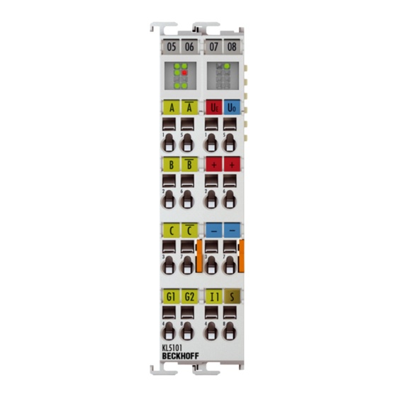
Fig. 2: KL5101 Incremental encoder interface The KL5101 terminal is an interface for direct connection of incremental encoders with difference signal (RS422) or single inputs. A 16-bit counter with a quadrature decoder and a 16-bit latch for the zero pulse can be read, set or enabled. -
Page 11: Kl5101 - Technical Data
Product overview KL5101 - Technical data Technical data KL5101 Encoder connection A, A(inv), B, B(inv), Null, Null(inv) Differential inputs (RS485), status input Encoder operating voltage 5 V Encoder output current 0.5 A Counter 16 bit, binary Limit frequency 4 million increments/s (with 4-fold evaluation) -
Page 12: Basic Function Principles
From hardware version 03 (i.e. from 18 June 1998) the KL5101 is delivered with new, additional features: • If the incremental encoder has an alarm output, it can be connected to the status input of the KL5101. • A period duration measurement with a resolution of 200 ns can also be carried out. -
Page 13: Fig. 3 Assignment Of The Terminal Contacts
• Ue: Power supply for the encoder (+5 V). • Uo: Power supply for the encoder (0 V). • 0 V, 24 V: A voltage supply of 0 V and 24 V must be connected to these contacts for operation of the terminal. KL5101 Version: 3.1... -
Page 14: Mounting And Wiring
• Each assembly must be terminated at the right hand end with a KL9010 bus end terminal, to ensure the protection class and ESD protection. Fig. 4: Spring contacts of the Beckhoff I/O components Installation on mounting rails WARNING... -
Page 15: Fig. 5 Attaching On Mounting Rail
To mount the mounting rails with a height of 7.5 mm under the terminals and couplers, you should use flat mounting connections (e.g. countersunk screws or blind rivets). KL5101 Version: 3.1... -
Page 16: Fig. 6 Disassembling Of Terminal
EL91xx, EL92xx) interrupt the power contacts and thus represent the start of a new supply rail. PE power contact The power contact labeled PE can be used as a protective earth. For safety reasons this contact mates first when plugging together, and can ground short-circuit currents of up to 125 A. Version: 3.1 KL5101... -
Page 17: Fig. 7 Power Contact On Left Side
Power Feed Terminals can be released and pulled at least 10 mm from the group of terminals. WARNING Risk of electric shock! The PE power contact must not be used for other potentials! KL5101 Version: 3.1... -
Page 18: Installation Instructions For Enhanced Mechanical Load Capacity
Overview The Bus Terminal system offers different connection options for optimum adaptation to the respective application: • The terminals of ELxxxx and KLxxxx series with standard wiring include electronics and connection level in a single enclosure. Version: 3.1 KL5101... -
Page 19: Fig. 8 Standard Wiring
Conductor cross sections between 0.08 mm and 2.5 mm can continue to be used with the proven spring force technology. The overview and nomenclature of the product names for ESxxxx and KSxxxx series has been retained as known from ELxxxx and KLxxxx series. KL5101 Version: 3.1... -
Page 20: Fig. 10 High Density Terminals
Ultrasonically "bonded" (ultrasonically welded) conductors Ultrasonically “bonded" conductors It is also possible to connect the Standard and High Density Terminals with ultrasonically "bonded" (ultrasonically welded) conductors. In this case, please note the tables concerning the wire-size width below! Version: 3.1 KL5101... -
Page 21: Wiring
The cables are released, as usual, using the contact release with the aid of a screwdriver. See the following table for the suitable wire size width. KL5101 Version: 3.1... -
Page 22: Shielding
80°C at the wire branching points, then cables must be selected whose tempera- ture data correspond to the actual measured temperature values! • Observe the permissible ambient temperature range of -25 to 60°C for the use of Beckhoff fieldbus com- ponents with extended temperature range (ET) in potentially explosive areas! •... -
Page 23: Atex Documentation
Notes about operation of the Beckhoff terminal systems in potentially explosive ar- eas (ATEX) Pay also attention to the continuative documentation Notes about operation of the Beckhoff terminal systems in potentially explosive areas (ATEX) that is available in the download area of the Beckhoff homepage http:\\www.beckhoff.com! KL5101... -
Page 24: Configuration Software Ks2000
Fieldbus Box modules with the aid of which settings can be modified easily. Alternatively, you have full access to all internal registers of the bus couplers and intelligent terminals. Refer to the register description for the meanings of the registers. Version: 3.1 KL5101... - Page 25 • Process values can be specified in the output image for commissioning of the output modules. All possibilities in the online mode can be used in parallel with the actual fieldbus mode of the terminal station. The fieldbus protocol always has the higher priority in this case. KL5101 Version: 3.1...
-
Page 26: Access From The User Program
This is always in the low byte on the offset address of the terminal channel. Fig. 13: Mapping for Lightbus Coupler - example for KL5101 BK3000 PROFIBUS coupler In the BK3000 Profibus coupler, the KL5101 is always mapped with 6 bytes of input data and 6 bytes of output data. Version: 3.1... -
Page 27: Fig. 14 Mapping For Profibus Coupler - Example For Kl5101
Fig. 14: Mapping for Profibus Coupler - example for KL5101 BK4000 Interbus Coupler The BK4000 Interbus coupler normally maps the KL5101 with 6 bytes of input data and 6 bytes of output data. Fig. 15: Mapping for Interbus Coupler - example for KL5101... -
Page 28: Mapping In The Bus Coupler
The following tables provide information about how the terminals map themselves in the Bus Coupler, depending on the parameters set. 5.2.1 Standard format The KL5101 is mapped into the bus coupler depending on the set parameters. The terminal always occupies memory space in the process image of the inputs and outputs. Conditions Word offset... -
Page 29: Register Overview
The Bus Coupler sees this structure. • R11: Signal channels Related to R10, this contains the number of channels that are logically present. Thus for example a shift register that is physically present can perfectly well consist of several signal channels. KL5101 Version: 3.1... - Page 30 If the write protection is active, the register contains a zero value. • R32: Feature register [0x2200] This register specifies the operation modes of the terminal. The default values are shown in square brackets. Version: 3.1 KL5101...
- Page 31 Input A: Counter Input B: Counting direction (5 V or open = up, 0 V = down) Input C: Latch • R33 - R47 Registers that depend on the terminal type. • R47 - R63 Extended registers with additional functions. KL5101 Version: 3.1...
-
Page 32: Control And Status Byte
The control byte is transferred from the controller to the terminal. It can be used • in register mode (REG = 1) or • in process data exchange (REG = 0). Various actions are triggered in the KL5101 with the control byte: Name REG=0... -
Page 33: Register Communication
Access from the user program Status byte for process data exchange The status byte is transmitted from the terminal to the controller. The status byte contains various status bits of the KL5101. Name REG=0 State_Input Overflow Underflow CntSet_Acc Latch_Ext_Val/ Latch_Val... -
Page 34: Fig. 16 Register Mode Control Byte
Example 1: Reading register 8 in the BK2000 with a KL5101 and the end terminal: If the following bytes are transferred from the controller to the terminal,... -
Page 35: Examples Of Register Communication
(power-off/power-on). I. Write the code word (0x1235) into Register 31. Output Data Byte 0: Control byte Byte 1: DataOUT1, high byte Byte 2: DataOUT1, low byte 0xDF (1101 1111 0x12 0x35 Explanation: KL5101 Version: 3.1... - Page 36 • Bit 0.6 set means: writing to the register. • Bits 0.5 to 0.0 indicate register number 32 with 10 0000 • The output data word (byte 1 and byte 2) contains the new value for the feature register. Version: 3.1 KL5101...
- Page 37 • Bit 0.6 set means: writing to the register. • Bits 0.5 to 0.0 specify the register number 31 with 01 1111 • The output data word (byte 1 and byte 2) contains 0x0000 for reactivating write protection. KL5101 Version: 3.1...
- Page 38 • The terminal returns a value as a receipt in the status byte that differs only in bit 0.6 from the value of the control byte. • The input data word (byte 1 and byte 2) is of no importance after the write access. Any values still displayed are invalid! Version: 3.1 KL5101...
-
Page 39: Appendix
Beckhoff's branch offices and representatives Please contact your Beckhoff branch office or representative for local support and service on Beckhoff products! The addresses of Beckhoff's branch offices and representatives round the world can be found on her internet pages: http://www.beckhoff.com You will also find further documentation for Beckhoff components there. - Page 40 Connecting a cable on a terminal point ..................Fig. 12 KS2000 configuration software....................Fig. 13 Mapping for Lightbus Coupler - example for KL5101 ..............Fig. 14 Mapping for Profibus Coupler - example for KL5101..............Fig. 15 Mapping for Interbus Coupler - example for KL5101..............
Need help?
Do you have a question about the KL5101 and is the answer not in the manual?
Questions and answers