
Related Manuals for Beckhoff EP2918-0032


Summary of Contents for Beckhoff EP2918-0032
- Page 1 Operating Instructions | EN EP2918-0032 and EP2918-2232 TwinSAFE EtherCAT Box with 8 fail-safe outputs 2022-10-20 | Version: 1.2.0...
-
Page 3: Table Of Contents
Configuration of the EtherCAT Box in TwinCAT ................ 24 4.3.1 Adding an EtherCAT device..................... 24 4.3.2 Inserting an EP2918...................... 24 4.3.3 EP2918-0032: using the integrated TwinSAFE Logic functions........ 24 4.3.4 Address settings on the TwinSAFE EtherCAT Box............ 26 4.3.5 Alias devices ........................ 27 4.3.6 EP2918 parameters ...................... - Page 4 Table of contents Service life............................ 45 Decommissioning .......................... 45 5 Appendix .............................. 46 Protection classes according to IP code .................. 46 Support and Service........................ 47 Certificates ............................ 48 Version: 1.2.0 EP2918-0032 and EP2918-2232...
-
Page 5: Foreword
Product features Only the product features specified in the current user documentation are valid. Further information given on the product pages of the Beckhoff homepage, in emails or in other publications is not authoritative. Disclaimer The documentation has been prepared with care. The products described are subject to cyclical revision. For that reason the documentation is not in every case checked for consistency with performance data, standards or other characteristics. -
Page 6: Safety Instructions
Delivery conditions In addition, the general delivery conditions of the company Beckhoff Automation GmbH & Co. KG apply. Currentness Please check whether you are using the current and valid version of this document. The current version can be downloaded from the Beckhoff homepage at http://www.beckhoff.de/twinsafe. -
Page 7: Description Of Instructions
NOTE Damage to the environment/equipment or data loss Failure to follow this instruction can lead to environmental damage, equipment damage or data loss. Tip or pointer This symbol indicates information that contributes to better understanding. EP2918-0032 and EP2918-2232 Version: 1.2.0... -
Page 8: Documentation Issue Status
• In chapter Technical data [} 11]Technical data link to download page of certificates added • Chapter "Firmware update of TwinSAFE products" removed • I/O component EP2918-2232 added as variant of EP2918-0032 • Chapter Temperature measurement [} 21] renamed • Chapter Project design limits of the EP2918 [} 25] moved •... -
Page 9: System Description
M8 or M12 connectors. Basic EtherCAT documentation You will find a detailed description of the EtherCAT system in the Basic System Documentation for EtherCAT, which is available for download from our website (www.beckhoff.com) under Downloads. EP2918-0032 and EP2918-2232 Version: 1.2.0... -
Page 10: Product Description
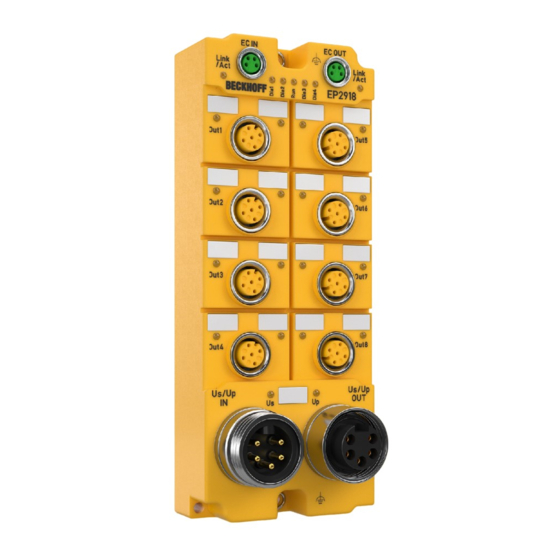
Product description Product description EP2918-0032 and EP2918-2232 The EP2918 is an EtherCAT Box with digital outputs for 24 V actuators. The EtherCAT Box has 8 fail-safe outputs, each with a maximum output current of 2 A (at 24 V The EL2918 meets the requirements of the following standards: •... -
Page 11: Intended Use
SAFE import or externally generated automatic project creation procedures, are not covered by the certifi- cate. WARNING Commissioning test Before the EP2918-0032 can be used for the safety task, the user must carry out a commissioning test so that sensor and actuator wiring faults can be ruled out. CAUTION Follow the machinery directive! The TwinSAFE components shall only be used in machines as defined in the machinery directive. - Page 12 Product description Product designation EP2918-0032 and EP2918-2232 Fieldbus EtherCAT Number of outputs Connection of the outputs Status display 8 (one green LED per output), 5 diagnostic LEDs, 2 LEDs for Us/Up, 2 LEDs for EtherCAT Link/Act Response time typical: 4 ms (in default setting without local TwinSAFE logic),...
-
Page 13: Safety Parameters
If the derating factor for the temperature for higher altitudes is used, the user is solely responsible for ensuring that the calculated maximum ambient temperature is complied with. Safety parameters Key data EP2918-0032 and EP2918-2232 Lifetime [a] Proof test interval [a] not required 4.16E-09 2.00E-05... -
Page 14: Safe Output
TRUE by default. Dimensions Fig. 3: Dimensions The EtherCAT Box has the following dimensions: Width 60.0 (+0.5) mm Height 150.0 (+0.5) mm Depth 26.5 mm When fully wired, the connected cables increase the total depth of the module. Version: 1.2.0 EP2918-0032 and EP2918-2232... -
Page 15: Operation
Connection 4.2.2.1 Nut torque for connectors M8 connector We recommend fastening the M8 connector with a torque of 0.4 Nm. A max. torque of 0.5 Nm is also permissible if using a torque screwdriver (Beckhoff article ZB8800). EP2918-0032 and EP2918-2232 Version: 1.2.0... -
Page 16: Fig. 4 Ethercat Box With M8 Plug Connectors
We recommend fastening the 7/8" plug connectors with a torque of 1.5 Nm. Fig. 6: 7/8" plug connectors Torque wrench Fig. 7: Torque wrench ZB8801 NOTE Ensure the proper torque is used Use torque wrenches available from Beckhoff to tighten the connectors (see accessories)! Version: 1.2.0 EP2918-0032 and EP2918-2232... -
Page 17: Fig. 8 Ethercat Connection 30 Mm Housing M8
EtherCAT/Ethernet infrastructure", which is available for download from www.Beck- hoff.de. EtherCAT uses four cable wires for signal transmission. Due to automatic cable detection (auto-crossing) symmetric (1:1) or cross-over cables can be used between EtherCAT devices from BECKHOFF. 4.2.2.4 Power connection and grounding This chapter provides basic information about the power supply and grounding of the TwinSAFE EtherCAT Box. - Page 18 (provide a 4 A fuse) Peripheral voltage Up, +24 V (provide a 16 A fuse) The contacts of the 7/8" plug connectors can conduct a maximum current of 16 A. Two LEDs indicate the status of the supply voltages. Version: 1.2.0 EP2918-0032 and EP2918-2232...
- Page 19 EtherCAT Box to EtherCAT Box in a simple manner. CAUTION Note the maximum current! Also ensure when forwarding the supply voltages Us and Up that the maximum permissible current of 16 A for each contact of the 7/8" plug connector is not exceeded! EP2918-0032 and EP2918-2232 Version: 1.2.0...
-
Page 20: Fig. 9: Safe Outputs 1 To 8
Operation 4.2.2.5 Signal connection for outputs The EtherCAT Box has 8 fail-safe outputs with a maximum output current of 2.0 A each (at 24 V Fig. 9: Safe outputs 1 to 8 Fig. 10: PinOut safe output Version: 1.2.0 EP2918-0032 and EP2918-2232... -
Page 21: Temperature Measurement
The temperature measurement of the TwinSAFE EtherCAT Box consists of a single EtherCAT Box that is wired with corresponding supply and communication cables. The inputs and/or outputs of the EtherCAT Box are switched on for the test. EP2918-0032 and EP2918-2232 Version: 1.2.0... -
Page 22: Signal Cables
When connecting a single switching contact via its own continuous cabling (or via a sheathed cable), the maximum permitted cable length with test pulses activated is 100 meters. The use of contact points, connectors or additional switching contacts in the cabling reduces the maximum propagation. Version: 1.2.0 EP2918-0032 and EP2918-2232... -
Page 23: Fig. 12 Cable Routing
The common routing of signals together with other clocked signals in a common cable also reduces the maximum propagation, since crosstalk of the signals can occur over long cable lengths and cause diagnostic messages. EP2918-0032 and EP2918-2232 Version: 1.2.0... -
Page 24: Configuration Of The Ethercat Box In Twincat
See TwinCAT automation software documentation. 4.3.2 Inserting an EP2918 An EP2918 is inserted in exactly the same way as any other Beckhoff EtherCAT Box. Open the TwinSAFE Fieldbus Boxes item in the list and select the EP2918. Fig. 13: Inserting an EP2918 4.3.3... -
Page 25: Fig. 14 Ep2918 - Delete Project Data
TwinCAT 3.1 Build 4022.28 or later is required for the use of the internal logic functions. If the EP2918 is used as a TwinSAFE slave with the default project, at least an EL6910, EK1960 or newer logic components are required as a TwinSAFE master. EP2918-0032 and EP2918-2232 Version: 1.2.0... -
Page 26: Address Settings On The Twinsafe Ethercat Box
3 (top) … … … … … … … … … … … … 4095 WARNING TwinSAFE address Each TwinSAFE address must be unique within a network! The address 0 is not a valid address. Version: 1.2.0 EP2918-0032 and EP2918-2232... -
Page 27: Alias Devices
The alias devices are created in the safety project when the dialog is closed via OK. Alternatively, the user can create the alias devices individually. To this end select Add and New item from the context menu, followed by the required device. EP2918-0032 and EP2918-2232 Version: 1.2.0... -
Page 28: Fig. 18 Creating Alias Devices By The User
Operation Fig. 18: Creating alias devices by the user Version: 1.2.0 EP2918-0032 and EP2918-2232... -
Page 29: Ep2918 Parameters
Display of the variables below the TwinSAFE Logic, e.g. EL6910 Output: Linked to In manual mode: Display of the linked variables Name In manual mode: Name of the TwinSAFE message below the TwinSAFE Logic and for the info data EP2918-0032 and EP2918-2232 Version: 1.2.0... -
Page 30: Fig. 20 Ep2918 - Connection Tab
The connection diagnostics is placed in the cyclic process data. Map inputs The safe input information of the connection is placed in the cyclic process data. Map outputs The safe output information of the connection is placed in the cyclic process data. Version: 1.2.0 EP2918-0032 and EP2918-2232... -
Page 31: Fig. 21 Ep2918 - Parameters
Parameters for FSOUT module 6 see module 1 see module 1 8060:01-07 Parameters for FSOUT module 7 see module 1 see module 1 8070:01-07 Parameters for FSOUT module 8 see module 1 see module 1 EP2918-0032 and EP2918-2232 Version: 1.2.0... -
Page 32: Process Image Of The Ep2918
Error acknowledge for safe output module 6 FSOUT Module7.Output Safe output 7 FSOUT Module7.ErrAck Error acknowledge for safe output module 7 FSOUT Module8.Output Safe output 8 FSOUT Module8.ErrAck Error acknowledge for safe output module 8 Version: 1.2.0 EP2918-0032 and EP2918-2232... -
Page 33: Twinsafe Reaction Times
The typical response time is based on the following formula: ReactionTime Sensor Input Comm Logic Comm Output Actuator with ReactionTime Worst case response time The worst-case response time is the maximum time required for switching off the actuator in the event of an error. EP2918-0032 and EP2918-2232 Version: 1.2.0... -
Page 34: Fig. 24 Worst Case Response Time
This fault is detected at the output once the watchdog time has elapsed, resulting in shutdown. This results in the following formula for the worst-case response time: ReactionTime Comm Comm Actuator with ReactionTime 2 *15 Version: 1.2.0 EP2918-0032 and EP2918-2232... -
Page 35: Diagnostics
ACT: Communication with the following EtherCAT module Status of the EtherCAT module is Init flashes quickly Status of the EtherCAT module is pre-operational flashes slowly Status of the EtherCAT module is safe-operational Status of the EtherCAT module is operational EP2918-0032 and EP2918-2232 Version: 1.2.0... -
Page 36: Status Leds
Output 7 is not connected Out 8 Output 8 is connected Output 8 is not connected Control voltage Us is available Control voltage Us is not available Peripheral voltage Up is present Peripheral voltage Up is not present Version: 1.2.0 EP2918-0032 and EP2918-2232... -
Page 37: Diagnostic Leds
Communication error in one of the TwinSAFE groups Error combination: Function block and communication General error in one of the TwinSAFE groups Error combination: General and function block Error combination: General and communication Error combination: General, function block and communication EP2918-0032 and EP2918-2232 Version: 1.2.0... -
Page 38: Flash Code Display
Vendor data CRC C2 CRC of the vendor data on µC2 Diagnostics history Any errors, which occur during operation of the TwinSAFE component, such as overtemperature or undervoltage, are entered in the diagnostics history with a corresponding timestamp. Version: 1.2.0 EP2918-0032 and EP2918-2232... -
Page 39: Fig. 28 Diagnostic Object - Fslogic Status (F100Hex) In The Process Image Of The Twinsafe Com- Ponent
This CoE object is additionally copied into the cyclic process image of the TwinSAFE component. From there, this information can be directly linked into the PLC. Fig. 28: Diagnostic object - FSLOGIC Status (F100 ) in the process image of the TwinSAFE component EP2918-0032 and EP2918-2232 Version: 1.2.0... -
Page 40: Cycle Time Of The Safety Project
Errors within the logic, the function blocks, the connections or the component itself are stored with a corresponding time stamp. Fig. 29: Diag history Use the Advanced… button to open the advanced settings. Here, the user can customize the behavior of the diag history. Version: 1.2.0 EP2918-0032 and EP2918-2232... -
Page 41: Diagnosis History
Both the control entries and the history itself can be found in the CoE object 0x10F3. The entry Newest Message (0x10F3:02) contains the subindex of 0x10F3, which contains the latest diagnostic message, e.g. 0x06 for diagnostic message 1. EP2918-0032 and EP2918-2232 Version: 1.2.0... - Page 42 TwinSAFE device. The age of the diagnosis message can be deduced by calculation with the current time stamp from the CoE object 0x10F8. Bit 5…7 reserved Bit 8…15 Number of parameters in this diagnosis message Version: 1.2.0 EP2918-0032 and EP2918-2232...
-
Page 43: Fig. 31 Esi/Xml Message Text
The sending of emergency messages to the EtherCAT master is activated by adding the CoE object 0x10F3:05 to the startup list (Transition IP, value 0x0001). If new diagnostic messages arrive, they are entered in object 0x10F3 and additionally sent by emergency to the EtherCAT master. Fig. 32: Startup list EP2918-0032 and EP2918-2232 Version: 1.2.0... -
Page 44: Maintenance
If the TwinSAFE component was subjected to unacceptable soiling it may no longer be operated! WARNING Have soiled terminals checked! Cleaning of the TwinSAFE component by the user is not permitted! Please send soiled terminals to the manufacturer for inspection and cleaning! Version: 1.2.0 EP2918-0032 and EP2918-2232... -
Page 45: Service Life
• Sealing compound: Polyurethane resin (PU552L) • Metal parts can be sent for metal recycling. • Electronic parts such as disk drives and circuit boards must be disposed of in accordance with national electronics scrap regulations. EP2918-0032 and EP2918-2232 Version: 1.2.0... -
Page 46: Appendix
30 minutes at a depth of 1 m must not have any adverse effects. *) These protection classes only define protection against water, not against other liquids. Version: 1.2.0 EP2918-0032 and EP2918-2232... -
Page 47: Support And Service
Please contact your Beckhoff branch office or representative for local support and service on Beckhoff products! The addresses of Beckhoff's branch offices and representatives round the world can be found on her internet pages: https://www.beckhoff.com You will also find further documentation for Beckhoff components there. -
Page 48: Certificates
Appendix Certificates Version: 1.2.0 EP2918-0032 and EP2918-2232... - Page 49 Diagnostic object - FSLOGIC Status (F100hex) in the process image of the TwinSAFE com- ponent ............................Fig. 29 Diag history ..........................Fig. 30 Diag history – advanced settings ....................Fig. 31 ESI/XML message text......................... Fig. 32 Startup list ............................ Fig. 33 EP2918 serial number and data code..................EP2918-0032 and EP2918-2232 Version: 1.2.0...
- Page 51 More Information: www.beckhoff.com/EP2918-0032 Beckhoff Automation GmbH & Co. KG Hülshorstweg 20 33415 Verl Germany Phone: +49 5246 9630 info@beckhoff.com www.beckhoff.com...
Need help?
Do you have a question about the EP2918-0032 and is the answer not in the manual?
Questions and answers