
Related Manuals for Beckhoff EL5032


Summary of Contents for Beckhoff EL5032
- Page 1 Documentation EL5032, EL5032-0090 2 channel EnDat2.2-Interface Version: Date: 2019-10-30...
-
Page 3: Table Of Contents
Two-channel ENDAT 2.2 interface - product overview.............. 5 Notes on the documentation...................... 5 Safety instructions .......................... 6 Documentation issue status ...................... 7 Version identification of EtherCAT devices .................. 7 1.5.1 Beckhoff Identification Code (BIC)................... 12 2 Product overview............................. 14 EL5032-00x0 - Introduction ...................... 14 Technical data .......................... 16 Start .............................. 16 3 Basics communication ........................... 17 EtherCAT basics.......................... 17... - Page 4 TwinSAFE SC.......................... 96 6.5.1 TwinSAFE SC - operating principle ................. 96 6.5.2 TwinSAFE SC - configuration .................. 96 EL5032-0090 - TwinSAFE SC process data ................. 100 EL5032-00x0 - object description and parameterization ............... 100 6.7.1 Restore object........................ 101 6.7.2 Configuration data ...................... 101 6.7.3...
-
Page 5: Foreword
EP1590927, EP1789857, EP1456722, EP2137893, DE102015105702 with corresponding applications or registrations in various other countries. ® EtherCAT is registered trademark and patented technology, licensed by Beckhoff Automation GmbH, Germany. Copyright © Beckhoff Automation GmbH & Co. KG, Germany. The reproduction, distribution and utilization of this document as well as the communication of its contents to others without express authorization are prohibited. -
Page 6: Safety Instructions
All the components are supplied in particular hardware and software configurations appropriate for the application. Modifications to hardware or software configurations other than those described in the documentation are not permitted, and nullify the liability of Beckhoff Automation GmbH & Co. KG. Personnel qualification This description is only intended for trained specialists in control, automation and drive engineering who are familiar with the applicable national standards. -
Page 7: Documentation Issue Status
• Addenda, corrections, 1st public issue • Complements, corrections • Complements, corrections • Provisional documentation for EL5032 Version identification of EtherCAT devices Designation A Beckhoff EtherCAT device has a 14-digit designation, made up of • family key • type • version • revision Example... - Page 8 Production lot/batch number/serial number/date code/D number The serial number for Beckhoff IO devices is usually the 8-digit number printed on the device or on a sticker. The serial number indicates the configuration in delivery state and therefore refers to a whole production batch, without distinguishing the individual modules of a batch.
-
Page 9: Fig. 1 El5021 El Terminal, Standard Ip20 Io Device With Serial/ Batch Number And Revision Id (Since 2014/01)
Fig. 1: EL5021 EL terminal, standard IP20 IO device with serial/ batch number and revision ID (since 2014/01) Fig. 2: EK1100 EtherCAT coupler, standard IP20 IO device with serial/ batch number Fig. 3: CU2016 switch with serial/ batch number EL5032, EL5032-0090 Version: 2.4... -
Page 10: Fig. 4 El3202-0020 With Serial/ Batch Number 26131006 And Unique Id-Number 204418
Fig. 5: EP1258-00001 IP67 EtherCAT Box with batch number/ date code 22090101 and unique serial number 158102 Fig. 6: EP1908-0002 IP67 EtherCAT Safety Box with batch number/ date code 071201FF and unique serial number 00346070 Fig. 7: EL2904 IP20 safety terminal with batch number/ date code 50110302 and unique serial number 00331701 Version: 2.4 EL5032, EL5032-0090... -
Page 11: Fig. 8 Elm3604-0002 Terminal With Unique Id Number (Qr Code) 100001051 And Serial/ Batch Num- Ber 44160201
Foreword Fig. 8: ELM3604-0002 terminal with unique ID number (QR code) 100001051 and serial/ batch number 44160201 EL5032, EL5032-0090 Version: 2.4... -
Page 12: Beckhoff Identification Code (Bic)
1.5.1 Beckhoff Identification Code (BIC) The Beckhoff Identification Code (BIC) is increasingly being applied to Beckhoff products to uniquely identify the product. The BIC is represented as a Data Matrix Code (DMC, code scheme ECC200), the content is based on the ANSI standard MH10.8.2-2016. - Page 13 Example of composite information from item 1 to 4 and 6. The data identifiers are marked in red for better display: An important component of the BIC is the Beckhoff Traceability Number (BTN, item no. 2). The BTN is a unique serial number consisting of eight characters that will replace all other serial number systems at Beckhoff in the long term (e.g.
-
Page 14: Product Overview
A list of additional information supported by the encoder is stored in the parameters. The EL5032 features distributed clocks, which means that the position value can be read in exact synchrony with the system. If the distributed clock function is deactivated, the EL5032 cycles synchronous with the EtherCAT cycle. -
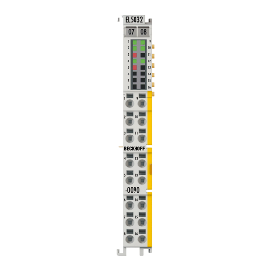
Page 15: Fig. 11 El5032-0090
Product overview EL5032-0090 Fig. 11: EL5032-0090 In addition to the full functionality of the EL5032-0000, the EL5032-0090 supports TwinSAFE SC (Single Channel) technology. This enables the use of standard signals for safety tasks in any networks of fieldbuses. Quick links • Basic Function Principles [} 28] •... -
Page 16: Technical Data
Start For commissioning: • mount the EL5032 as explained in the chapter Mounting and wiring [} 34] • configure the EL5032 in TwinCAT as described in the chapter Commissioning [} 50]. For fast commissioning please refer to chapter Commissioning -> Quick start [} 50]. -
Page 17: Basics Communication
EtherCAT devices from Beckhoff. Recommended cables Suitable cables for the connection of EtherCAT devices can be found on the Beckhoff website! E-Bus supply A bus coupler can supply the EL terminals added to it with the E-bus system voltage of 5 V; a coupler is thereby loadable up to 2 A as a rule (see details in respective device documentation). -
Page 18: General Notes For Setting The Watchdog
The PDI watchdog monitors correct and timely process data communication with the ESC from the application side. The settings of the SM- and PDI-watchdog must be done for each slave separately in the TwinCAT System Manager. Version: 2.4 EL5032, EL5032-0090... -
Page 19: Fig. 13 Ethercat Tab -> Advanced Settings -> Behavior -> Watchdog
The standard setting of 1000 for the SM watchdog corresponds to a release time of 100 ms. The value in multiplier + 2 corresponds to the number of basic 40 ns ticks representing a watchdog tick. The multiplier can be modified in order to adjust the watchdog time over a larger range. EL5032, EL5032-0090 Version: 2.4... -
Page 20: Ethercat State Machine
EtherCAT master to the device in each state, particularly during the bootup of the slave. A distinction is made between the following states: • Init • Pre-Operational • Safe-Operational and • Operational • Boot The regular state of each EtherCAT slave after bootup is the OP state. Version: 2.4 EL5032, EL5032-0090... -
Page 21: Fig. 14 States Of The Ethercat State Machine
Before the EtherCAT master switches the EtherCAT slave from Safe-Op to Op it must transfer valid output data. In the Op state the slave copies the output data of the masters to its outputs. Process data and mailbox communication is possible. EL5032, EL5032-0090 Version: 2.4... -
Page 22: Coe Interface
Not every EtherCAT device must have a CoE list. Simple I/O modules without dedicated processor usually have no variable parameters and therefore no CoE list. If a device has a CoE list, it is shown in the TwinCAT System Manager as a separate tab with a listing of the elements: Version: 2.4 EL5032, EL5032-0090... -
Page 23: Fig. 15 "Coe Online " Tab
Data management If slave CoE parameters are modified online, Beckhoff devices store any changes in a fail-safe manner in the EEPROM, i.e. the modified CoE parameters are still available after a restart. The situation may be different with other manufacturers. -
Page 24: Fig. 16 Startup List In The Twincat System Manager
Changes in the local CoE list of the terminal are lost if the terminal is replaced. If a terminal is re- placed with a new Beckhoff terminal, it will have the default settings. It is therefore advisable to link all changes in the CoE list of an EtherCAT slave with the Startup list of the slave, which is pro- cessed whenever the EtherCAT fieldbus is started. -
Page 25: Fig. 17 Offline List
◦ The actual current slave list is read. This may take several seconds, depending on the size and cycle time. ◦ The actual identity is displayed ◦ The firmware and hardware version of the equipment according to the electronic information is displayed ◦ Online is shown in green. Fig. 18: Online list EL5032, EL5032-0090 Version: 2.4... - Page 26 • Channel 1: parameter range 0x8010:00 ... 0x801F:255 • Channel 2: parameter range 0x8020:00 ... 0x802F:255 • ... This is generally written as 0x80n0. Detailed information on the CoE interface can be found in the EtherCAT system documentation on the Beckhoff website. Version: 2.4 EL5032, EL5032-0090...
-
Page 27: Distributed Clock
4.2 seconds) • The EtherCAT master automatically synchronizes the local clock with the master clock in the EtherCAT bus with a precision of < 100 ns. For detailed information please refer to the EtherCAT system description. EL5032, EL5032-0090 Version: 2.4... -
Page 28: Basics Of Endat 2.2 Technology
Some encoders also provide incremental signals. These are usually used to increase the resolution of the position value, or to serve a second subsequent electronics unit. Current generations of encoders have a high internal resolution, and therefore no longer need to provide incremental signals. Version: 2.4 EL5032, EL5032-0090... - Page 29 **) Source: Dr. Johannes HEIDENHAIN GmbH Connection of HEIDENHAIN EnDat-interfaces to the EL5032 The EL5032 can only be connected to measuring instruments that support a clock frequency of 8 MHz. This corresponds to the order designation EnDat22. Encoders with the ordering designation EnDat02 can be operated at 8MHz on the EL5032 without incremental signals using an appropriate adapter cable.
-
Page 30: Connection Technology
8 MHz can be implemented and the EL5032 can be used. **) Source: Dr. Johannes HEIDENHAIN GmbH Data transfer from incremental or absolute sensors to the EL5032 can take place with a simple shielded 8- wire cable (Fig. Connection of measuring sensors and EL5032). -
Page 31: Functional Description
Extended diagnostics from FW15 From FW15 the EL5032 offers extended diagnostics for the EnDat error message with multi-turn ro- tary encoders with battery buffer. The battery operating state error sources are not automatically re- set;... - Page 32 Basics of EnDat 2.2 technology These errors can be reset using the command 0x8001 "EnDat Reset". An overview of the commands and examples of their use can be found in the chapter "Overview of commands and examples [} 93]". Version: 2.4 EL5032, EL5032-0090...
-
Page 33: Data Transfer
Clock frequency – cable length With the runtime compensation employed in the EL5032, a cable length of maximally 100 m is possible with a clock frequency of 8 MHz. Correspondingly suitable cables and plug connectors must be used in order to guarantee the function. -
Page 34: Mounting And Wiring
• Each assembly must be terminated at the right hand end with an EL9011 or EL9012 bus end cap, to en- sure the protection class and ESD protection. Fig. 22: Spring contacts of the Beckhoff I/O components Installation on mounting rails... -
Page 35: Fig. 23 Attaching On Mounting Rail
To mount the mounting rails with a height of 7.5 mm under the terminals and couplers, you should use flat mounting connections (e.g. countersunk screws or blind rivets). EL5032, EL5032-0090 Version: 2.4... -
Page 36: Fig. 24 Disassembling Of Terminal
EL91xx, EL92xx) interrupt the power contacts and thus represent the start of a new supply rail. PE power contact The power contact labeled PE can be used as a protective earth. For safety reasons this contact mates first when plugging together, and can ground short-circuit currents of up to 125 A. Version: 2.4 EL5032, EL5032-0090... -
Page 37: Fig. 25 Power Contact On Left Side
Power Feed Terminals can be released and pulled at least 10 mm from the group of terminals. WARNING Risk of electric shock! The PE power contact must not be used for other potentials! EL5032, EL5032-0090 Version: 2.4... -
Page 38: Installation Instructions For Enhanced Mechanical Load Capacity
Overview The Bus Terminal system offers different connection options for optimum adaptation to the respective application: • The terminals of ELxxxx and KLxxxx series with standard wiring include electronics and connection level in a single enclosure. Version: 2.4 EL5032, EL5032-0090... -
Page 39: Fig. 26 Standard Wiring
2.5 mm can continue to be used with the proven spring force technology. The overview and nomenclature of the product names for ESxxxx and KSxxxx series has been retained as known from ELxxxx and KLxxxx series. EL5032, EL5032-0090 Version: 2.4... -
Page 40: Fig. 28 High Density Terminals
Ultrasonically "bonded" (ultrasonically welded) conductors Ultrasonically “bonded" conductors It is also possible to connect the Standard and High Density Terminals with ultrasonically "bonded" (ultrasonically welded) conductors. In this case, please note the tables concerning the wire-size width below! Version: 2.4 EL5032, EL5032-0090... -
Page 41: Wiring
The cables are released, as usual, using the contact release with the aid of a screwdriver. See the following table for the suitable wire size width. EL5032, EL5032-0090 Version: 2.4... -
Page 42: Shielding
EL/KL terminals to face forward (see Fig. “Recommended distances for standard installation position”). The terminals are ventilated from below, which enables optimum cooling of the electronics through convection. "From below" is relative to the acceleration of gravity. Version: 2.4 EL5032, EL5032-0090... -
Page 43: Fig. 30 Recommended Distances For Standard Installation Position
Other installation positions All other installation positions are characterized by different spatial arrangement of the mounting rail - see Fig “Other installation positions”. The minimum distances to ambient specified above also apply to these installation positions. EL5032, EL5032-0090 Version: 2.4... -
Page 44: Fig. 31 Other Installation Positions
Mounting and wiring Fig. 31: Other installation positions Version: 2.4 EL5032, EL5032-0090... -
Page 45: Positioning Of Passive Terminals
E-Bus. To ensure an optimal data transfer, you must not directly string together more than 2 passive termi- nals! Examples for positioning of passive terminals (highlighted) Fig. 32: Correct positioning Fig. 33: Incorrect positioning EL5032, EL5032-0090 Version: 2.4... -
Page 46: Atex - Special Conditions (Standard Temperature Range)
80°C at the wire branching points, then cables must be selected whose tempera- ture data correspond to the actual measured temperature values! • Observe the permissible ambient temperature range of 0 to 55°C for the use of Beckhoff fieldbus compo- nents standard temperature range in potentially explosive areas! •... -
Page 47: Atex Documentation
Beckhoff EtherCAT modules are intended for use with Beckhoff’s UL Listed EtherCAT Sys- tem only. Examination For cULus examination, the Beckhoff I/O System has only been investigated for risk of fire and electrical shock (in accordance with UL508 and CSA C22.2 No. 142). For devices with Ethernet connectors Not for connection to telecommunication circuits. -
Page 48: Leds And Connection
Error during initialization (see diag history [} 116]) No error ENC SUPPLY green Encoder voltage available 24 V field voltage missing or encoder voltage overload RX 1 (10) green FLASHES Terminal receives position values at the corresponding channel RX 2 (12) Version: 2.4 EL5032, EL5032-0090... -
Page 49: Fig. 35 Connection
Clock - input (channel 1) Ground Shield Shield Data 2- Data - input (channel 2) Clock 2- Clock - input (channel 2) Ground Shield Shield Further connection information Further connection information can be found in the chapter "Technology [} 28]". EL5032, EL5032-0090 Version: 2.4... -
Page 50: Commissioning
Proceed as follows for standard commissioning of the EL5032 with EnDat 2.2 encoders. 1. Install the EL5032 in the E-bus terminal strand on an EtherCAT coupler, e.g. EK1100 or EK1501. 2. Connect the EnDat 2.2 encoder(s) according to the connection diagram (Data(+/-), Clock(+/-) and sup- ply voltage). -
Page 51: Installation Of The Twincat Real-Time Driver
6.2.1 Installation of the TwinCAT real-time driver In order to assign real-time capability to a standard Ethernet port of an IPC controller, the Beckhoff real-time driver has to be installed on this port under Windows. This can be done in several ways. One option is described here. -
Page 52: Fig. 38 Overview Of Network Interfaces
TwinCAT 3: the properties of the EtherCAT device can be opened by double click on “Device .. (EtherCAT)” within the Solution Explorer under “I/O”: After the installation the driver appears activated in the Windows overview for the network interface (Windows Start → System Properties → Network) Version: 2.4 EL5032, EL5032-0090... -
Page 53: Fig. 40 Windows Properties Of The Network Interface
Commissioning Fig. 40: Windows properties of the network interface A correct setting of the driver could be: Fig. 41: Exemplary correct driver setting for the Ethernet port Other possible settings have to be avoided: EL5032, EL5032-0090 Version: 2.4... - Page 54 Commissioning Fig. 42: Incorrect driver settings for the Ethernet port Version: 2.4 EL5032, EL5032-0090...
- Page 55 DHCP. In this way the delay associated with the DHCP client for the Ethernet port assigning itself a default IP address in the absence of a DHCP server is avoided. A suitable address space is 192.168.x.x, for example. Fig. 43: TCP/IP setting for the Ethernet port EL5032, EL5032-0090 Version: 2.4...
-
Page 56: Notes Regarding Esi Device Description
The files are read (once) when a new System Manager window is opened, if they have changed since the last time the System Manager window was opened. A TwinCAT installation includes the set of Beckhoff ESI files that was current at the time when the TwinCAT build was created. - Page 57 1018 in the configuration. This is also stated by the Beckhoff compatibility rule. Refer in particular to the chapter ‘General notes on the use of Beckhoff EtherCAT IO components’ and for manual configuration to the chapter ‘Offline configuration creation’ [} 61].
- Page 58 Faulty ESI file If an ESI file is faulty and the System Manager is unable to read it, the System Manager brings up an information window. Fig. 49: Information window for faulty ESI file (left: TwinCAT 2; right: TwinCAT 3) Version: 2.4 EL5032, EL5032-0090...
- Page 59 Commissioning Reasons may include: • Structure of the *.xml does not correspond to the associated *.xsd file → check your schematics • Contents cannot be translated into a device description → contact the file manufacturer EL5032, EL5032-0090 Version: 2.4...
-
Page 60: Twincat Esi Updater
Commissioning 6.2.3 TwinCAT ESI Updater For TwinCAT 2.11 and higher, the System Manager can search for current Beckhoff ESI files automatically, if an online connection is available: Fig. 50: Using the ESI Updater (>= TwinCAT 2.11) The call up takes place under: “Options” → "Update EtherCAT Device Descriptions"... -
Page 61: Offline Configuration Creation
EL6601/EL6614 terminal select “EtherCAT Automation Protocol via EL6601”. Fig. 53: Selecting the EtherCAT connection (TwinCAT 2.11, TwinCAT 3) Then assign a real Ethernet port to this virtual device in the runtime system. Fig. 54: Selecting the Ethernet port EL5032, EL5032-0090 Version: 2.4... - Page 62 Fig. “Selection dialog for new EtherCAT device”. If the preceding device has several free ports (e.g. EK1122 or EK1100), the required port can be selected on the right-hand side (A). Overview of physical layer • “Ethernet”: cable-based 100BASE-TX: EK couplers, EP boxes, devices with RJ45/M8/M12 connector Version: 2.4 EL5032, EL5032-0090...
- Page 63 (i.e. highest) revision and therefore the latest state of production is displayed in the selection dialog for Beckhoff devices. To show all device revisions available in the system as ESI descriptions tick the “Show Hidden Devices” check box, see Fig. “Display of previous revisions”.
- Page 64 If current ESI descriptions are available in the TwinCAT system, the last revision offered in the selection dialog matches the Beckhoff state of production. It is recommended to use the last device revision when creating a new configuration, if current Beckhoff devices are used in the real application. Older revisions should only be used if older devices from stock are to be used in the application.
- Page 65 Commissioning Fig. 61: EtherCAT terminal in the TwinCAT tree (left: TwinCAT 2; right: TwinCAT 3) EL5032, EL5032-0090 Version: 2.4...
-
Page 66: Online Configuration Creation
This scan mode attempts to find not only EtherCAT devices (or Ethernet ports that are usable as such), but also NOVRAM, fieldbus cards, SMB etc. However, not all devices can be found automatically. Fig. 64: Note for automatic device scan (left: TwinCAT 2; right: TwinCAT 3) Version: 2.4 EL5032, EL5032-0090... - Page 67 [} 71] with the defined initial configuration.Background: since Beckhoff occasionally increases the revision version of the delivered products for product maintenance reasons, a configuration can be created by such a scan which (with an identical machine construction) is identical according to the device list;...
- Page 68 Likewise, A might create spare parts stores worldwide for the coming series-produced machines with EL2521-0025-1018 terminals. After some time Beckhoff extends the EL2521-0025 by a new feature C. Therefore the FW is changed, outwardly recognizable by a higher FW version and a new revision -1019. Nevertheless the new device naturally supports functions and interfaces of the predecessor version(s);...
- Page 69 Fig. 73: Displaying of “Free Run” and “Config Mode” toggling right below in the status bar Fig. 74: TwinCAT can also be switched to this state by using a button (left: TwinCAT 2; right: TwinCAT 3) The EtherCAT system should then be in a functional cyclic state, as shown in Fig. “Online display example”. EL5032, EL5032-0090 Version: 2.4...
- Page 70 The connections and devices should be checked in a targeted manner, e.g. via the emergency scan. Then re-run the scan. Fig. 76: Faulty identification In the System Manager such devices may be set up as EK0000 or unknown devices. Operation is not possible or meaningful. Version: 2.4 EL5032, EL5032-0090...
- Page 71 A ‘ChangeTo’ or ‘Copy’ should only be carried out with care, taking into consideration the Beckhoff IO compatibility rule (see above). The device configuration is then replaced by the revision found; this can affect the supported process data and functions.
- Page 72 If current ESI descriptions are available in the TwinCAT system, the last revision offered in the selection dialog matches the Beckhoff state of production. It is recommended to use the last device revision when creating a new configuration, if current Beckhoff devices are used in the real application. Older revisions should only be used if older devices from stock are to be used in the application.
- Page 73 This function is preferably to be used on AX5000 devices. Change to Alternative Type The TwinCAT System Manager offers a function for the exchange of a device: Change to Alternative Type Fig. 82: TwinCAT 2 Dialog Change to Alternative Type EL5032, EL5032-0090 Version: 2.4...
-
Page 74: Ethercat Subscriber Configuration
Here you can add a comment (e.g. regarding the system). Disabled Here you can deactivate the EtherCAT device. Create symbols Access to this EtherCAT slave via ADS is only available if this control box is activated. Version: 2.4 EL5032, EL5032-0090... - Page 75 CANopen process data objects (Process Data Objects, PDOs). The user can select a PDO via PDO assignment and modify the content of the individual PDO via this dialog, if the EtherCAT slave supports this function. EL5032, EL5032-0090 Version: 2.4...
- Page 76 For Beckhoff EtherCAT EL, ES, EM, EJ and EP slaves the following applies in general: • The input/output process data supported by the device are defined by the manufacturer in the ESI/XML description.
- Page 77 (CoE) or Servo drive over EtherCAT protocol. This tab indicates which download requests are sent to the mailbox during startup. It is also possible to add new mailbox requests to the list display. The download requests are sent to the slave in the same order as they are shown in the list. EL5032, EL5032-0090 Version: 2.4...
- Page 78 (CoE) protocol. This dialog lists the content of the object list of the slave (SDO upload) and enables the user to modify the content of an object from this list. Details for the objects of the individual EtherCAT devices can be found in the device-specific object descriptions. Version: 2.4 EL5032, EL5032-0090...
- Page 79 Auto Update If this check box is selected, the content of the objects is updated automatically. Advanced The Advanced button opens the Advanced Settings dialog. Here you can specify which objects are displayed in the list. EL5032, EL5032-0090 Version: 2.4...
- Page 80 Offline - via EDS File If this option button is selected, the list of the objects included in the object list is read from an EDS file provided by the user. „Online“ tab Fig. 91: „Online“ tab Version: 2.4 EL5032, EL5032-0090...
- Page 81 Operation Mode Options (optional): • FreeRun • SM-Synchron • DC-Synchron (Input based) • DC-Synchron Advanced Settings… Advanced settings for readjustment of the real time determinant TwinCAT- clock Detailed information to Distributed Clocks are specified on http://infosys.beckhoff.com: EL5032, EL5032-0090 Version: 2.4...
- Page 82 Sync Manager! Consequently, this PDO cannot be deleted from the PDO Assignment list Sync Manager to which this PDO is assigned. If this entry is empty, this PDO does not take part in the process data traffic. Sync unit to which this PDO is assigned. Version: 2.4 EL5032, EL5032-0090...
-
Page 83: General Notes - Ethercat Slave Application
Those diagnostic elements that are helpful to the controlling task for diagnosis that is accurate for the current cycle when in operation (not during commissioning) are discussed below. Fig. 93: Selection of the diagnostic information of an EtherCAT Slave EL5032, EL5032-0090 Version: 2.4... - Page 84 Fig. “Basic EtherCAT Slave Diagnosis in the PLC” shows an example of an implementation of basic EtherCAT Slave Diagnosis. A Beckhoff EL3102 (2-channel analogue input terminal) is used here, as it offers both the communication diagnosis typical of a slave and the functional diagnosis that is specific to a channel.
- Page 85 The CoE parameter directory (CanOpen-over-EtherCAT) is used to manage the set values for the slave concerned. Changes may, in some circumstances, have to be made here when commissioning a relatively complex EtherCAT Slave. It can be accessed through the TwinCAT System Manager, see Fig. “EL3102, CoE directory”: EL5032, EL5032-0090 Version: 2.4...
- Page 86 Commissioning interfaces are being introduced as part of an ongoing process for EL/EP EtherCAT devices. These are available in TwinCAT System Managers from TwinCAT 2.11R2 and above. They are integrated into the System Manager through appropriately extended ESI configuration files. Version: 2.4 EL5032, EL5032-0090...
- Page 87 The target state wanted by the user, and which is brought about automatically at start-up by TwinCAT, can be set in the System Manager. As soon as TwinCAT reaches the status RUN, the TwinCAT EtherCAT Master will approach the target states. EL5032, EL5032-0090 Version: 2.4...
- Page 88 Fig. 97: Default behaviour of the System Manager In addition, the target state of any particular Slave can be set in the "Advanced Settings" dialogue; the standard setting is again OP. Fig. 98: Default target state in the Slave Version: 2.4 EL5032, EL5032-0090...
- Page 89 The pre-calculated theoretical maximum E-Bus current is displayed in the TwinCAT System Manager as a column value. A shortfall is marked by a negative total amount and an exclamation mark; a power feed terminal is to be placed before such a position. EL5032, EL5032-0090 Version: 2.4...
-
Page 90: Version: 2.4 El5032, El5032
Fig. 101: Warning message for exceeding E-Bus current NOTE Caution! Malfunction possible! The same ground potential must be used for the E-Bus supply of all EtherCAT terminals in a terminal block! Version: 2.4 EL5032, EL5032-0090... -
Page 91: Process Data
To configure the process data, select the required Sync Manager (SM 2 or SM 3) in the "Sync Manager" field at the top left (see Fig. Process data tab SM3, EL5032 (default)). The process data assigned to this Sync Manager can then be switched on or off in the “PDO Assignment” box underneath. Restarting the EtherCAT system, or reloading the configuration in configuration mode (F4), causes the EtherCAT communication to restart, and the process data is transferred from the terminal. - Page 92 Index 0x6010:02 [} 102] compact Status_Ready Index 0x6010:03 [} 102] [Offset] [Offset] Status_Diag Index 0x6010:0D [} 102] Status_TxPDO State Index 0x6010:0E [} 102] Status_Input Cycle counter Index 0x6010:0F [} 102] Position Index 0x6010:11 [} 102] Table 1: PDO assignment of sync managers, EL5032 Version: 2.4 EL5032, EL5032-0090...
-
Page 93: Predefined Pdo Assignment
0x1A00 [} 108] (FB Inputs Channel 2) 2 Ch. Compact 0x1A02 [} 109] (FB Inputs Channel 2 compact) Fig. 103: Process data tab - Predefined PDO Assignment, EL5032 6.4.4 Overview of commands and samples The FB EnDat Command Object 0xB0n8 [} 102] can be used to initiate various actions, such as reading... - Page 94 Commissioning Fig. 104: Entry of the command in the Set Value dialogue of the System Manager Version: 2.4 EL5032, EL5032-0090...
- Page 95 0: Acknowledge LOBYTE command 5-byte acknowledgement header + 1-word data 1: Acknowledge HIBYTE command 0x34 = LOBYTE of "0x1234" 2: Acknowledge MRS code 0x12 = HIBYTE of "0x1234" 3: Acknowledge offset 4: Acknowledge length in words EL5032, EL5032-0090 Version: 2.4...
-
Page 96: Twinsafe Sc
Slots tab. Only then is it possible to link to a corresponding alias device. Fig. 105: Adding the TwinSAFE SC process data under the component, e.g. EL5021-0090 Additional process data with the ID TSC Inputs, TSC Outputs are generated (TSC - TwinSAFE Single Channel). Fig. 106: TwinSAFE SC component process data, example EL5021-0090 Version: 2.4 EL5032, EL5032-0090... - Page 97 TwinSAFE SC CRC 3 master 0x11F95 TwinSAFE SC CRC 4 master 0x153F1 TwinSAFE SC CRC 5 master 0x1F1D5 TwinSAFE SC CRC 6 master 0x1663B TwinSAFE SC CRC 7 master 0x1B8CD TwinSAFE SC CRC 8 master 0x1E1BD EL5032, EL5032-0090 Version: 2.4...
- Page 98 Process Image tab. Fig. 110: Selecting the process data size and the process data The process data (defined in the ESI file) can be adjusted to user requirements by selecting the Edit button in the dialog Configure I/O element(s). Version: 2.4 EL5032, EL5032-0090...
- Page 99 Depending on the terminal, the index designation of the configuration object TSC Settings can vary. Example: - EL3214-0090 and EL3314-0090, TSC Settings, Index 8040 - EL5021-0090, TSC Settings, Index 8010 - EL6224-0090, TSC Settings, Index 800F Fig. 113: Entering the safety address and the CRC EL5032, EL5032-0090 Version: 2.4...
-
Page 100: El5032-0090 - Twinsafe Sc Process Data
◦ An individual number of bits can be specified by which the process data is to be shifted to the right. TwinSAFE SC objects The overview of the TwinSAFE SC objects of the EL5032-0090 can be found in the chapter EL5032-0090 - TwinSAFE Single Channel objects [} 113]. -
Page 101: Restore Object
9.0 V, it must be ensured that both EnDat encoders support the ex- tended voltage range! The setting is only adopted in the “INIT” state. The encoder supply voltage is set for both channels in object 0x80p8! EL5032, EL5032-0090 Version: 2.4... -
Page 102: Command Object
In this case the process data must be parameter- ized under 0x8021 [} 115] "TSC Process Data settings". 60p0:12 Position (uint32) EnDat position value (unit32) UINT32 00 00 00 00 Also see about this 2 EL5032-0090 - TwinSAFE Single Channel objects [} 113] Version: 2.4 EL5032, EL5032-0090... -
Page 103: Information Data
Limit position warning supported 90p8:38 Not ready warning supported 90p8:39 Diagnostic warning supported 90p8:43 Temperature 1 (exter- nal) supported 90p8:44 Temperature 2 (inter- nal) supported 90p8:51 Clock pulse periods Number of position bits UINT16 0x0000 (0dec) EL5032, EL5032-0090 Version: 2.4... -
Page 104: Diagnostic Data
0x0000 (0 10F3:06 Diagnosis Message Message 1 OCTET- STRING[28] 10F3:37 Diagnosis Message Message 50 OCTET- STRING[28] Index 10F8 Actual Time Stamp Index (hex) Name Meaning Data type Flags Default 10F8:0 Actual Time Stamp Time stamp UINT64 Version: 2.4 EL5032, EL5032-0090... - Page 105 FALSE: none TRUE: yes A0p8:25 Undervoltage error Undervoltage BOOLEAN FALSE FALSE: none TRUE: supply undervoltage A0p8:26 Overcurrent error Overcurrent BOOLEAN FALSE FALSE: no TRUE: yes A0p8:27 Battery error Battery BOOLEAN FALSE FALSE: OK TRUE: change required EL5032, EL5032-0090 Version: 2.4...
-
Page 106: Standard Objects
Data type Flags Default 1009:0 Hardware version Hardware version of the EtherCAT slave STRING Index 100A Software version Index (hex) Name Meaning Data type Flags Default 100A:0 Software version Firmware version of the EtherCAT slave STRING Version: 2.4 EL5032, EL5032-0090... - Page 107 FB TxPDO-Par Inputs PDO parameter TxPDO 4 UINT8 > 6 < Ch.2 compact 1803:06 Exclude TxPDOs Specifies the TxPDOs (index of TxPDO mapping objects) OCTET- 01 1A that must not be transferred together with TxPDO 4 STRING[2] EL5032, EL5032-0090 Version: 2.4...
- Page 108 8. PDO Mapping entry (object 0x6000 (FB Inputs Ch.1), UINT32 0x6010:0F entry 0x0F (Input cycle counter)) [} 102], 2 1A01:09 SubIndex 009 9. PDO Mapping entry (object 0x6000 (FB Inputs Ch.1), UINT32 0x6010:11 entry 0x11 (Position)) [} 102], 64 Version: 2.4 EL5032, EL5032-0090...
- Page 109 SubIndex 004 Sync-Manager Type Channel 4: Process Data Read (In- UINT8 0x04 (4 puts) Index 1C12 RxPDO assign Index (hex) Name Meaning Data type Flags Default 1C12:0 RxPDO assign PDO Assign Outputs UINT8 > 0 < EL5032, EL5032-0090 Version: 2.4...
- Page 110 Commissioning Index 1C12 RxPDO assign (EL5032-0090) Index (hex) Name Meaning Data type Flags Default 1C12:0 RxPDO assign PDO Assign Outputs UINT8 > 1 < 1C12:1 SubIndex 001 1. allocated RxPDO (contains the index of the associated UINT16 0x1610 (5648) RxPDO mapping object)
- Page 111 Commissioning Index 1C32 SM output parameter (EL5032-0090 only) Index (hex) Name Meaning Data type Flags Default 1C32:0 SM output parameter Synchronization parameters for the outputs UINT8 > 32 < 1C32:01 Sync mode Current synchronization mode: UINT16 0x0001 (1 • 0: Free Run •...
- Page 112 UINT8 > 2 < F000:01 Module index dis- Index distance of the objects of the individual channels UINT16 0x0010 (16 tance F000:02 Maximum number of Number of channels UINT16 EL5032: modules 0x0002 (2 EL5032-0090: 0x0003 (3 Version: 2.4 EL5032, EL5032-0090...
-
Page 113: El5032-0090 - Twinsafe Single Channel Objects
0x00000000 FB40:02 Length reserved UINT16 0x0000 (0 FB40:03 Data reserved OCTET- STRING[8] EL5032-0090 - TwinSAFE Single Channel objects Index 1610 TSC Master Message Index (hex) Name Meaning Data type Flags Default 1610:0 TSC RxPDO-Map PDO Mapping RxPDO UINT8 0x04 (4... - Page 114 Index 8020 TSC Settings Index (hex) Name Meaning Data type Flags Default 8020:0 TSC Settings Maximum subindex UINT8 0x02 (2 8020:01 Address TwinSAFE SC address UINT16 0x0000 (0 8020:02 Connection Mode Selection of TwinSAFE SC CRC UINT32 0x00000000 Version: 2.4 EL5032, EL5032-0090...
- Page 115 0x00 (0 • Default: 0 – the position value is shifted by 0 bits to the right. • An individual number of bits can be specified by which the process data is to be shifted to the right. EL5032, EL5032-0090 Version: 2.4...
-
Page 116: Diagnostics
The DiagMessages are explained in text form in the ESI/XML file belonging to the EtherCAT device: on the basis of the Text ID contained in the DiagMessage, the corresponding plain text message can be found in the languages contained in the ESI/XML. In the case of Beckhoff products these are usually German and English. - Page 117 As a remedy, external synchronization of the DC time can be used, or a manual correction calculation can be applied, as required: The current DC time can be determined via the EtherCAT master or from register x901 of the DC slave. EL5032, EL5032-0090 Version: 2.4...
- Page 118 Structure of the Text ID The structure of the MessageID is not subject to any standardization and can be supplier-specifically defined. In the case of Beckhoff EtherCAT devices (EL, EP) it usually reads according to xyzz: 0: Systeminfo 0: System...
- Page 119 0x170C Information Calibration data saved Calibration data were saved 0x170D Information Calibration data will be Calibration data are not applied and saved until the applied and saved after command "0x5AFE" is sent sending the command “0x5AFE” EL5032, EL5032-0090 Version: 2.4...
- Page 120 Information System %s: UDP handler initial- UDP handler initialized ized 0x2008 Information System %s: TCP handler initial- TCP handler initialized ized 0x2009 Information System %s: No more free TCP No free TCP sockets available. sockets available Version: 2.4 EL5032, EL5032-0090...
- Page 121 Activation of the out- put stage is prevented 0x4413 Warning Drive I2T-Model Amplifier - The amplifier is being operated outside the specifica- overload (Warning) tion - The I2T-model of the amplifier is incorrectly parame- terized EL5032, EL5032-0090 Version: 2.4...
- Page 122 Processor usage at %d Processor load at %d %% 0x470A Warning EtherCAT Frame missed EtherCAT frame missed (change DC Operation Mode (change Settings or DC or Sync0 Shift Time under Settings) Operation Mode or Sync0 Shift Time) Version: 2.4 EL5032, EL5032-0090...
- Page 123 Error Communication Key Creation failed: %X 0x8284 Error Communication Key loading failed 0x8285 Error Communication Reading Public Key failed: %X 0x8286 Error Communication Reading Public EK failed: %X 0x8287 Error Communication Reading PCR Value failed: %X EL5032, EL5032-0090 Version: 2.4...
- Page 124 The internal temperature of the motor exceeds the pa- rameterized error threshold. The motor stops immedi- ately. Activation of the output stage is prevented. 0x8417 Error Drive Maximum rotating field Rotary field speed exceeds the value specified for dual velocity exceeded use (EU 1382/2014). Version: 2.4 EL5032, EL5032-0090...
- Page 125 Saturationtime was ma- Saturation time was manipulated nipulated 0x870A Error Channel range error Measuring range error for the channel 0x870B Error no ADC clock No ADC clock available 0xFFFF Information Debug: 0x%X, 0x%X, 0x Debug: 0x%X, 0x%X, 0x%X EL5032, EL5032-0090 Version: 2.4...
-
Page 126: Appendix
Check on the Beckhoff web page whether more up-to-date documentation is available. Firmware Update EL/ES/EM/ELM/EPxxxx This section describes the device update for Beckhoff EtherCAT slaves from the EL/ES, ELM, EM, EK and EP series. A firmware update should only be carried out after consultation with Beckhoff support. -
Page 127: Device Description Esi File/Xml
EtherCAT communication is set up accordingly. The device description is available from the download area of the Beckhoff website at (https://www.beckhoff.de). All ESI files are accessible there as zip files. Customers can access the data via the EtherCAT fieldbus and its communication mechanisms. Acyclic mailbox communication or register access to the ESC is used for updating or reading of these data. - Page 128 The device revision is closely linked to the firmware and hardware used. Incompatible combinations lead to malfunctions or even final shutdown of the device. Corresponding updates should only be carried out in consultation with Beckhoff support. Display of ESI slave identifier...
- Page 129 The ESI/EEPROM identifier can be updated as follows under TwinCAT: • Trouble-free EtherCAT communication must be established with the slave. • The state of the slave is irrelevant. • Right-clicking on the slave in the online display opens the EEPROM Update dialog, Fig. EEPROM Update EL5032, EL5032-0090 Version: 2.4...
-
Page 130: Firmware Explanation
Firmware explanation Determining the firmware version Determining the version on laser inscription Beckhoff EtherCAT slaves feature serial numbers applied by laser. The serial number has the following structure: KK YY FF HH KK - week of production (CW, calendar week) -
Page 131: Updating Controller Firmware *.Efw
• offline: The EtherCAT Slave Information ESI/XML may contain the default content of the CoE. This CoE directory can only be displayed if it is included in the ESI (e.g. "Beckhoff EL5xxx.xml"). The Advanced button must be used for switching between the two views. - Page 132 Appendix Fig. 123: Firmware Update Proceed as follows, unless instructed otherwise by Beckhoff support. Valid for TwinCAT 2 and 3 as EtherCAT master. • Switch TwinCAT system to ConfigMode/FreeRun with cycle time >= 1 ms (default in ConfigMode is 4 ms). A FW-Update during real time operation is not recommended.
-
Page 133: Fpga Firmware *.Rbf
The TwinCAT System Manager indicates the FPGA firmware version. Click on the Ethernet card of your EtherCAT strand (Device 2 in the example) and select the Online tab. The Reg:0002 column indicates the firmware version of the individual EtherCAT devices in hexadecimal and decimal representation. EL5032, EL5032-0090 Version: 2.4... - Page 134 Fig. 125: Context menu Properties The Advanced Settings dialog appears where the columns to be displayed can be selected. Under Diagnosis/Online View select the '0002 ETxxxx Build' check box in order to activate the FPGA firmware version display. Version: 2.4 EL5032, EL5032-0090...
- Page 135 Older firmware versions can only be updated by the manufacturer! Updating an EtherCAT device The following sequence order have to be met if no other specifications are given (e.g. by the Beckhoff support): • Switch TwinCAT system to ConfigMode/FreeRun with cycle time >= 1 ms (default in ConfigMode is 4 ms).
- Page 136 • In the TwinCAT System Manager select the terminal for which the FPGA firmware is to be updated (in the example: Terminal 5: EL5001) and click the Advanced Settings button in the EtherCAT tab: • The Advanced Settings dialog appears. Under ESC Access/E²PROM/FPGA click on Write FPGA button: Version: 2.4 EL5032, EL5032-0090...
-
Page 137: Simultaneous Updating Of Several Ethercat Devices
The firmware and ESI descriptions of several devices can be updated simultaneously, provided the devices have the same firmware file/ESI. Fig. 127: Multiple selection and firmware update Select the required slaves and carry out the firmware update in BOOTSTRAP mode as described above. EL5032, EL5032-0090 Version: 2.4... -
Page 138: Restoring The Delivery State
Fig. 129: Entering a restore value in the Set Value dialog Alternative restore value In some older terminals the backup objects can be switched with an alternative restore value: Deci- mal value: 1819238756, Hexadecimal value: 0x6C6F6164An incorrect entry for the restore value has no effect. Version: 2.4 EL5032, EL5032-0090... -
Page 139: Support And Service
Beckhoff's branch offices and representatives Please contact your Beckhoff branch office or representative for local support and service on Beckhoff products! The addresses of Beckhoff's branch offices and representatives round the world can be found on her internet pages: http://www.beckhoff.com You will also find further documentation for Beckhoff components there. - Page 140 Online list ............................ Fig. 19 Signal cables and power supply for the EnDat 2.2 interface** ............ Fig. 20 Connection of measuring sensor and EL5032................Fig. 21 Illustration of instruction set for EnDat 2.2 and 2.1** ..............Fig. 22 Spring contacts of the Beckhoff I/O components.................
- Page 141 Fig. 81 Dialog “Change to Compatible Type…” (left: TwinCAT 2; right: TwinCAT 3) ......Fig. 82 TwinCAT 2 Dialog Change to Alternative Type ................Fig. 83 Branch element as terminal EL3751.................... Fig. 84 “General” tab..........................Fig. 85 „EtherCAT“ tab..........................EL5032, EL5032-0090 Version: 2.4...
- Page 142 Fig. 101 Warning message for exceeding E-Bus current ................. Fig. 102 Process data tab SM3, EL5032 (default)..................Fig. 103 Process data tab - Predefined PDO Assignment, EL5032 ............Fig. 104 Entry of the command in the Set Value dialogue of the System Manager ........
Need help?
Do you have a question about the EL5032 and is the answer not in the manual?
Questions and answers