
Subscribe to Our Youtube Channel
Related Manuals for Beckhoff EL5101


Summary of Contents for Beckhoff EL5101
- Page 1 Documentation EL5101, EL5101-0010, EL5101-0011 Incremental Encoder Interface Version: Date: 2017-07-31...
-
Page 3: Table Of Contents
Notes regarding ESI device description ................ 80 6.2.3 TwinCAT ESI Updater...................... 84 6.2.4 Distinction between Online and Offline ................ 84 6.2.5 OFFLINE configuration creation .................. 85 6.2.6 ONLINE configuration creation .................. 90 6.2.7 EtherCAT subscriber configuration .................. 98 6.2.8 NC configuration ...................... 108 EL5101, EL5101-0010, EL5101-0011 Version: 4.2... -
Page 4: Fig. 35 El5101
Table of contents General Notes - EtherCAT Slave Application ................ 111 EL5101-00x0 .......................... 119 6.4.1 Normal operation mode .................... 119 6.4.2 Enhanced operation mode ..................... 129 EL5101-0011 .......................... 157 6.5.1 Principles of the oversampling function ................. 157 6.5.2 Process data and configuration .................. 159 6.5.3... -
Page 5: Overview Incremental Encoder Interface
Overview Incremental Encoder Interface Overview Incremental Encoder Interface EL5101-0000 [} 13] (Incremental Encoder Interface) EL5101-0010 [} 13] (Incremental Encoder Interface, 20 Mio. increments/s) EL5101-0011 [} 14] (Incremental Encoder Interface, with oversampling) EL5101, EL5101-0010, EL5101-0011 Version: 4.2... -
Page 6: Foreword
The TwinCAT Technology is covered, including but not limited to the following patent applications and patents: EP0851348, US6167425 with corresponding applications or registrations in various other countries. ® EtherCAT is registered trademark and patented technology, licensed by Beckhoff Automation GmbH, Germany Copyright © Beckhoff Automation GmbH & Co. KG, Germany. -
Page 7: Safety Instructions
All the components are supplied in particular hardware and software configurations appropriate for the application. Modifications to hardware or software configurations other than those described in the documentation are not permitted, and nullify the liability of Beckhoff Automation GmbH & Co. KG. Personnel qualification This description is only intended for trained specialists in control, automation and drive engineering who are familiar with the applicable national standards. -
Page 8: Documentation Issue Status
- Correction of the note "Non-Volatile Settings" - Extended description for status LEDs added - First provisional documentation for EL5101 Version identification of EtherCAT devices Designation A Beckhoff EtherCAT device has a 14-digit designation, made up of • family key • type • version • revision Version: 4.2... - Page 9 Production lot/batch number/serial number/date code/D number The serial number for Beckhoff IO devices is usually the 8-digit number printed on the device or on a sticker. The serial number indicates the configuration in delivery state and therefore refers to a whole production batch, without distinguishing the individual modules of a batch.
-
Page 10: Fig. 1 El5021 El Terminal, Standard Ip20 Io Device With Batch Number And Revision Id (Since 2014/01)
• Terminals with factory calibration certificate and other measuring terminals Examples of markings Fig. 1: EL5021 EL terminal, standard IP20 IO device with batch number and revision ID (since 2014/01) Fig. 2: EK1100 EtherCAT coupler, standard IP20 IO device with batch number Version: 4.2 EL5101, EL5101-0010, EL5101-0011... -
Page 11: Fig. 3 Cu2016 Switch With Batch Number
Fig. 4: EL3202-0020 with batch numbers 26131006 and unique ID-number 204418 Fig. 5: EP1258-00001 IP67 EtherCAT Box with batch number 22090101 and unique serial number 158102 Fig. 6: EP1908-0002 IP67 EtherCAT Safety Box with batch number 071201FF and unique serial number 00346070 EL5101, EL5101-0010, EL5101-0011 Version: 4.2... -
Page 12: Fig. 7 El2904 Ip20 Safety Terminal With Batch Number/Date Code 50110302 And Unique Serial Num- Ber 00331701
Foreword Fig. 7: EL2904 IP20 safety terminal with batch number/date code 50110302 and unique serial number 00331701 Fig. 8: ELM3604-0002 terminal with ID number (QR code) 100001051 and unique serial number 44160201 Version: 4.2 EL5101, EL5101-0010, EL5101-0011... -
Page 13: Product Overview
The gate input allows the locking of the counter, alternatively with a high or low level. The latch input is similarly configurable and evaluates high or low levels. The EL5101-0000 can also be used as bidirectional counter on channel A; channel B specifies the count direction. -
Page 14: Fig. 10 El5101-0011
(oversampling factor: n) of the bus cycle time. The transfer of a packet of n position values of 32 bits each to the higher-level controller takes place in the next fieldbus communication cycle. The minimum sampling time here is 10 µs (100 kSps). Areas of application of the EL5101-0011 lie in particular in the area of high- resolution position detection. -
Page 15: Technology
Table 1: Operating modes EL5101-0000 The EL5101-0010 with a resolution of 20 mio. increments/s at 5 MHz and 4-fold evaluation is only applicable for the enhanced operating mode. The inputs can process differential signals according to RS485. The microincrement mode is not available for the EL5101-0010. - Page 16 EtherCAT cycle time For the EL5101 a minimum EtherCAT cycle time of >100 µs is recommended. If a faster cycle time is used, the toggling process record TxPDO Toggle should be used to monitor when new process data are supplied by the EL5101.
-
Page 17: Fig. 11 Level Interface
If the EL5101 is only operated in single-ended mode, a nominal level voltage between 3.5 V and 5.5 V is expected. The EL5101-0010 and EL5101-0011 do not support single-ended mode. -
Page 18: Technical Data
EMC immunity/emission conforms to EN 61000-6-2 / EN 61000-6-4 Protection class IP20 Installation position variable Approval ATEX [} 45] cULus [} 43] Start For commissioning: • mount the EL5101 as described in the chapter Mounting and wiring [} 34] Version: 4.2 EL5101, EL5101-0010, EL5101-0011... - Page 19 Product overview • configure the EL5101 in TwinCAT as described in the chapter Commissioning [} 50]. EL5101, EL5101-0010, EL5101-0011 Version: 4.2...
-
Page 20: Basics Communication
Due to automatic cable detection (auto-crossing) symmetric (1:1) or cross-over cables can be used between EtherCAT devices from Beckhoff. Recommended cables Suitable cables for the connection of EtherCAT devices can be found on the Beckhoff web- site! Note E-Bus supply A bus coupler can supply the EL terminals added to it with the E-bus system voltage of 5 V;... -
Page 21: General Notes For Setting The Watchdog
The PDI watchdog monitors correct and timely process data communication with the ESC from the application side. The settings of the SM- and PDI-watchdog must be done for each slave separately in the TwinCAT System Manager. EL5101, EL5101-0010, EL5101-0011 Version: 4.2... -
Page 22: Fig. 13 Ethercat Tab -> Advanced Settings -> Behavior -> Watchdog
The value in multiplier + 2 corresponds to the number of basic 40 ns ticks representing a watchdog tick. The multiplier can be modified in order to adjust the watchdog time over a larger range. Version: 4.2 EL5101, EL5101-0010, EL5101-0011... -
Page 23: Ethercat State Machine
EtherCAT master to the device in each state, particularly during the bootup of the slave. A distinction is made between the following states: • Init • Pre-Operational • Safe-Operational and • Operational • Boot The regular state of each EtherCAT slave after bootup is the OP state. EL5101, EL5101-0010, EL5101-0011 Version: 4.2... -
Page 24: Fig. 14 States Of The Ethercat State Machine
Before the EtherCAT master switches the EtherCAT slave from Safe-Op to Op it must transfer valid output data. In the Op state the slave copies the output data of the masters to its outputs. Process data and mailbox communication is possible. Version: 4.2 EL5101, EL5101-0010, EL5101-0011... -
Page 25: Coe Interface
CoE list. Note If a device has a CoE list, it is shown in the TwinCAT System Manager as a separate tab with a listing of the elements: EL5101, EL5101-0010, EL5101-0011 Version: 4.2... -
Page 26: Fig. 15 "Coe Online " Tab
"SetValue" dialog. • from the control system/PLC via ADS, e.g. through blocks from the TcEtherCAT.lib library This is recommended for modifications while the system is running or if no System Manager or operating staff are available. Version: 4.2 EL5101, EL5101-0010, EL5101-0011... -
Page 27: Fig. 16 Startup List In The Twincat System Manager
Startup list Changes in the local CoE list of the terminal are lost if the terminal is replaced. If a terminal is replaced with a new Beckhoff terminal, it will have the default settings. It is therefore ad- Note visable to link all changes in the CoE list of an EtherCAT slave with the Startup list of the slave, which is processed whenever the EtherCAT fieldbus is started. -
Page 28: Fig. 17 Offline List
◦ The actual current slave list is read. This may take several seconds, depending on the size and cycle time. ◦ The actual identity is displayed ◦ The firmware and hardware version of the equipment according to the electronic information is displayed ◦ Online is shown in green. Version: 4.2 EL5101, EL5101-0010, EL5101-0011... -
Page 29: Dc Settings
Beckhoff website: the “Distributed clocks system description”. Note The incremental encoder terminals support the distributed clocks function (EL5101: from Hardware 09 / Firmware 14; EL5151 from Hardware 01 / Firmware 05). In order for the EL51xx to be able to make the current counter value available in the designated process data in time before the arrival of the querying EtherCAT datagram, a suitable signal must be generated cyclically within the terminal. -
Page 30: Fig. 19 "Dc" Tab (Distributed Clocks)
EtherCAT datagram. Duration of the process data provision in the EL51x1 The EL5101 (from Hardware 09 / Firmware 14) or the EL5151 (from Hardware 01/ Firmware 05) requires approx. 80 µs after the SYNC event to determine the position data Note and provide them for retrieval. -
Page 31: Fig. 20 Advanced Distributed Clock (Dc) Settings, El51Xx Terminal
EtherCAT datagram. This setting may be useful in systems with high real-time jitter, if no Industrial PCs from Beckhoff are used for control purposes, for example. Attention! Risk of device damage! The mentioned notes and information should be used advisedly. -
Page 32: Fig. 21 Ethercat Master, Ethercat Tab, Advanced Settings
Higher-level distributed clock parameters can be modified under advanced settings for the EtherCAT master. Refer also to the basic introduction to the topic of EtherCAT and Distributed Clocks; download: the “Distributed clocks system description”. Fig. 21: EtherCAT Master, EtherCAT tab, Advanced Settings Version: 4.2 EL5101, EL5101-0010, EL5101-0011... -
Page 33: Fig. 22 Ethercat Master, Ethercat Tab, Advanced Settings
Basics communication Fig. 22: EtherCAT Master, EtherCAT tab, Advanced Settings Fig. 23: EtherCAT Master, Advanced Settings, Distributed Clock EL5101, EL5101-0010, EL5101-0011 Version: 4.2... -
Page 34: Mounting And Wiring
To mount the mounting rails with a height of 7.5 mm under the terminals and couplers, you should use flat mounting connections (e.g. countersunk screws or blind rivets). Version: 4.2 EL5101, EL5101-0010, EL5101-0011... -
Page 35: Fig. 25 Disassembling Of Terminal
PE power contact The power contact labeled PE can be used as a protective earth. For safety reasons this contact mates first when plugging together, and can ground short-circuit currents of up to 125 A. EL5101, EL5101-0010, EL5101-0011 Version: 4.2... -
Page 36: Installation Instructions For Enhanced Mechanical Load Capacity
10 frequency runs in 3 axes 6 Hz < f < 60 Hz displacement 0.35 mm, constant amplitude 60.1 Hz < f < 500 Hz acceleration 5 g, constant amplitude Shocks 1000 shocks in each direction, in 3 axes 25 g, 6 ms Version: 4.2 EL5101, EL5101-0010, EL5101-0011... -
Page 37: Connection
Standard wiring (ELxxxx / KLxxxx) Fig. 27: Standard wiring The terminals of ELxxxx and KLxxxx series have been tried and tested for years. They feature integrated screwless spring force technology for fast and simple assembly. EL5101, EL5101-0010, EL5101-0011 Version: 4.2... -
Page 38: Fig. 28 Pluggable Wiring
Ultrasonically “bonded" conductors It is also possible to connect the Standard and High Density Terminals with ultrasonically "bonded" (ultrasonically welded) conductors. In this case, please note the tables concern- Note ing the wire-size width below! Version: 4.2 EL5101, EL5101-0010, EL5101-0011... -
Page 39: Wiring
The cables are released, as usual, using the contact release with the aid of a screwdriver. See the following table for the suitable wire size width. EL5101, EL5101-0010, EL5101-0011 Version: 4.2... -
Page 40: Shielding
EL/KL terminals to face forward (see Fig. “Recommended distances for standard installation position”). The terminals are ventilated from below, which enables optimum cooling of the electronics through convection. "From below" is relative to the acceleration of gravity. Version: 4.2 EL5101, EL5101-0010, EL5101-0011... -
Page 41: Fig. 31 Recommended Distances For Standard Installation Position
Other installation positions All other installation positions are characterized by different spatial arrangement of the mounting rail - see Fig “Other installation positions”. The minimum distances to ambient specified above also apply to these installation positions. EL5101, EL5101-0010, EL5101-0011 Version: 4.2... -
Page 42: Mounting Of Passive Terminals
Passive Terminals. The Passive Terminals have Note no current consumption out of the E-Bus To ensure an optimal data transfer, you must not directly string together more than 2 Passive Terminals! Examples for mounting passive terminals (highlighted) Fig. 33: Correct configuration Version: 4.2 EL5101, EL5101-0010, EL5101-0011... -
Page 43: Ul Notice
Beckhoff EtherCAT modules are intended for use with Beckhoff’s UL Listed EtherCAT Sys- tem only. Examination For cULus examination, the Beckhoff I/O System has only been investigated for risk of fire and electrical shock (in accordance with UL508 and CSA C22.2 No. 142). For devices with Ethernet connectors Not for connection to telecommunication circuits. - Page 44 A voltage source complying with NEC class 2 may not be connected in series or parallel with another NEC class 2 compliant voltage supply! These requirements apply to the supply of all EtherCAT bus couplers, power adaptor terminals, Bus Terminals and their power contacts. Version: 4.2 EL5101, EL5101-0010, EL5101-0011...
-
Page 45: Atex - Special Conditions (Extended Temperature Range)
• EN 60079-0:2012+A11:2013 • EN 60079-15:2010 Marking The Beckhoff fieldbus components with extended temperature range (ET) certified for potentially explosive areas bear the following marking: II 3G KEMA 10ATEX0075 X Ex nA IIC T4 Gc Ta: -25 … 60°C II 3G KEMA 10ATEX0075 X Ex nC IIC T4 Gc Ta: -25 … 60°C EL5101, EL5101-0010, EL5101-0011 Version: 4.2... -
Page 46: Atex Documentation
Notes about operation of the Beckhoff terminal systems in potentially explo- sive areas (ATEX) Pay also attention to the continuative documentation Note Notes about operation of the Beckhoff terminal systems in potentially explosive areas (ATEX) that is available in the download area of the Beckhoff homepage http:\\www.beckhoff.com! LEDs and connection 5.9.1... - Page 47 Sync Manager [} 98] channels and the distributed clocks. Outputs remain in safe state State of the EtherCAT State Machine: OP = normal operating state; mailbox and process data communication is possible POWER 5 V green Operating voltage display for incremental encoder power supply EL5101, EL5101-0010, EL5101-0011 Version: 4.2...
-
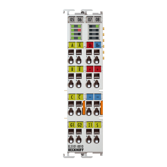
Page 48: El5101-0011
0 V (internally connected to terminal point 7' and negative power contact) Uo = 0 V 0 V encoder supply +24 V +24 V (internally connected to terminal point 2' and positive power contact) 0 V 0 V (internally connected to terminal point 3' and negative power contact) Shield Shield Version: 4.2 EL5101, EL5101-0010, EL5101-0011... - Page 49 Outputs remain in safe state State of the EtherCAT State Machine: OP = normal operating state; mailbox and process data communication is possible POWER 5 V green Operating voltage display for incremental encoder power supply EL5101, EL5101-0010, EL5101-0011 Version: 4.2...
-
Page 50: Commissioning
• "offline": The configuration can be customized by adding and positioning individual components. These can be selected from a directory and configured. ◦ The procedure for offline mode can be found under http://infosys.beckhoff.com: TwinCAT 2 → TwinCAT System Manager → IO - Configuration → Adding an I/O Device •... -
Page 51: Fig. 37 Relationship Between User Side (Commissioning) And Installation
• Linked via the X001 port (RJ-45): EK1100 EtherCAT Coupler • Connected to the EK1100 EtherCAT coupler on the right (E-bus): EL2008 (8-channel digital output terminal 24 V DC; 0.5 A) • (Optional via X000: a link to an external PC for the user interface) EL5101, EL5101-0010, EL5101-0011 Version: 4.2... -
Page 52: Fig. 38 Control Configuration With Embedded Pc, Input (El1004) And Output (El2008)
The starting point is the TwinCAT System Manager. After successful installation of the TwinCAT system on the PC to be used for development, the TwinCAT 2 System Manager displays the following user interface after startup: Fig. 39: Initial TwinCAT 2 user interface Version: 4.2 EL5101, EL5101-0010, EL5101-0011... -
Page 53: Fig. 40 Selection Of The Target System
Fig. 41: Specify the PLC for access by the TwinCAT System Manager: selection of the target system Once the target system has been entered, it is available for selection as follows (a password may have to be entered): EL5101, EL5101-0010, EL5101-0011 Version: 4.2... - Page 54 Confirm the message "Find new boxes", in order to determine the terminals connected to the devices. "Free Run" enables manipulation of input and output values in "Config mode" and should also be acknowledged. Based on the sample configuration [} 51] described at the beginning of this section, the result is as follows: Version: 4.2 EL5101, EL5101-0010, EL5101-0011...
- Page 55 TwinCAT PLC Control is the development environment for the creation of the controller in different program environments: TwinCAT PLC Control supports all languages described in IEC 61131-3. There are two text- based languages and three graphical languages. • Text-based languages ◦ Instruction List (IL) ◦ Structured Text (ST) EL5101, EL5101-0010, EL5101-0011 Version: 4.2...
- Page 56 After starting TwinCAT PLC Control, the following user interface is shown for an initial project: Fig. 46: TwinCAT PLC Control after startup Sample variables and a sample program have been created and stored under the name "PLC_example.pro": Version: 4.2 EL5101, EL5101-0010, EL5101-0011...
- Page 57 Manager has been notified, the warning no longer appears. First, integrate the TwinCAT PLC Control project in the System Manager via the context menu of the PLC configuration; right-click and select "Append PLC Project…": Fig. 48: Appending the TwinCAT PLC Control project EL5101, EL5101-0010, EL5101-0011 Version: 4.2...
- Page 58 "PLC_example" and via "Modify Link..." "Standard": Fig. 50: Creating the links between PLC variables and process objects In the window that opens, the process object for the variable “bEL1004_Ch4” of type BOOL can be selected from the PLC configuration tree: Version: 4.2 EL5101, EL5101-0010, EL5101-0011...
- Page 59 The links can also be checked by selecting a "Goto Link Variable” from the context menu of a variable. The object opposite, in this case the PDO, is automatically selected: EL5101, EL5101-0010, EL5101-0011 Version: 4.2...
- Page 60 The PLC system can then be started as described below. Starting the controller Starting from a remote system, the PLC control has to be linked with the Embedded PC over Ethernet via "Online" → “Choose Run-Time System…": Version: 4.2 EL5101, EL5101-0010, EL5101-0011...
- Page 61 This results in the message "No program on the controller! Should the new program be loaded?", which should be acknowledged with "Yes". The runtime environment is ready for the program start: EL5101, EL5101-0010, EL5101-0011 Version: 4.2...
- Page 62 (cf. "TwinCAT System Manager" of TwinCAT 2) for communication with the electromechanical components. After successful installation of the TwinCAT system on the PC to be used for development, TwinCAT 3 (shell) displays the following user interface after startup: Version: 4.2 EL5101, EL5101-0010, EL5101-0011...
- Page 63 (or under "File"→“New"→ "Project…"). In the following dialog make the corresponding entries as required (as shown in the diagram): Fig. 57: Create new TwinCAT project The new project is then available in the project folder explorer: EL5101, EL5101-0010, EL5101-0011 Version: 4.2...
- Page 64 Via the symbol in the menu bar: expand the pull-down menu: and open the following window: Fig. 59: Selection dialog: Choose the target system Version: 4.2 EL5101, EL5101-0010, EL5101-0011...
- Page 65 The TwinCAT System Manager may first have to be set to "Config mode" via or via the menu "TwinCAT" → "Restart TwinCAT (Config mode)". Fig. 61: Select "Scan" Confirm the warning message, which follows, and select "EtherCAT" in the dialog: EL5101, EL5101-0010, EL5101-0011 Version: 4.2...
- Page 66 The whole process consists of two stages, which may be performed separately (first determine the devices, then determine the connected elements such as boxes, terminals, etc.). A scan can also be initiated by selecting "Device ..." from the context menu, which then reads the elements present in the configuration below: Version: 4.2 EL5101, EL5101-0010, EL5101-0011...
- Page 67 The following section refers to Structured Text (ST). In order to create a programming environment, a PLC subproject is added to the project sample via the context menu of "PLC" in the project folder explorer by selecting "Add New Item….": EL5101, EL5101-0010, EL5101-0011 Version: 4.2...
- Page 68 Fig. 66: Specifying the name and directory for the PLC programming environment The "Main" program, which already exists by selecting "Standard PLC project", can be opened by double- clicking on "PLC_example_project" in "POUs”. The following user interface is shown for an initial project: Version: 4.2 EL5101, EL5101-0010, EL5101-0011...
- Page 69 Commissioning Fig. 67: Initial "Main" program of the standard PLC project To continue, sample variables and a sample program have now been created: EL5101, EL5101-0010, EL5101-0011 Version: 4.2...
- Page 70 "Assignments" in the project folder explorer: Assigning variables Via the menu of an instance - variables in the "PLC” context, use the "Modify Link…" option to open a window for selecting a suitable process object (PDO) for linking: Version: 4.2 EL5101, EL5101-0010, EL5101-0011...
- Page 71 4 of the EL1004 terminal is selected for linking. In contrast, the checkbox "All types" must be ticked for creating the link for the output variables, in order to allocate a set of eight separate output bits to a byte variable. The following diagram shows the whole process: EL5101, EL5101-0010, EL5101-0011 Version: 4.2...
- Page 72 PDO, it is possible to allocate this a set of bit-standardised variables (type "BOOL"). Here, too, a "Goto Link Variable” from the context menu of a PDO can be executed in the other direction, so that the respective PLC instance can then be selected. Version: 4.2 EL5101, EL5101-0010, EL5101-0011...
- Page 73 Fig. 74: TwinCAT development environment (VS shell): logged-in, after program startup The two operator control elements for stopping and logout result in the required action (accordingly also for stop "Shift + F5", or both actions can be selected via the PLC menu). EL5101, EL5101-0010, EL5101-0011 Version: 4.2...
-
Page 74: Twincat 2
6.2.1 Installation of the TwinCAT real-time driver In order to assign real-time capability to a standard Ethernet port of an IPC controller, the Beckhoff real-time driver has to be installed on this port under Windows. This can be done in several ways. One option is described here. - Page 75 Alternatively an EtherCAT-device can be inserted first of all as described in chapter Offline configuration creation, section “Creating the EtherCAT device” [} 85] in order to view the compatible ethernet ports via its EtherCAT properties (tab „Adapter“, button „Compatible Devices…“): EL5101, EL5101-0010, EL5101-0011 Version: 4.2...
- Page 76 After the installation the driver appears activated in the Windows overview for the network interface (Windows Start → System Properties → Network) Fig. 79: Windows properties of the network interface A correct setting of the driver could be: Version: 4.2 EL5101, EL5101-0010, EL5101-0011...
- Page 77 Commissioning Fig. 80: Exemplary correct driver setting for the Ethernet port Other possible settings have to be avoided: EL5101, EL5101-0010, EL5101-0011 Version: 4.2...
- Page 78 Commissioning Fig. 81: Incorrect driver settings for the Ethernet port Version: 4.2 EL5101, EL5101-0010, EL5101-0011...
- Page 79 DHCP. In this way the delay associated with the DHCP client for the Ethernet port assigning itself a default IP address in the absence of a DHCP server is avoided. A suitable address space is 192.168.x.x, for example. Fig. 82: TCP/IP setting for the Ethernet port EL5101, EL5101-0010, EL5101-0011 Version: 4.2...
-
Page 80: Notes Regarding Esi Device Description
The files are read (once) when a new System Manager window is opened, if they have changed since the last time the System Manager window was opened. A TwinCAT installation includes the set of Beckhoff ESI files that was current at the time when the TwinCAT build was created. - Page 81 1018 in the configuration. This is also stated by the Beckhoff compatibility rule. Refer in particular to the chapter ‘General notes on the use of Beckhoff EtherCAT IO components’ and for manual configuration to the chapter ‘Offline configuration creation’ [} 85].
- Page 82 Faulty ESI file If an ESI file is faulty and the System Manager is unable to read it, the System Manager brings up an information window. Fig. 88: Information window for faulty ESI file (left: TwinCAT 2; right: TwinCAT 3) Version: 4.2 EL5101, EL5101-0010, EL5101-0011...
- Page 83 Commissioning Reasons may include: • Structure of the *.xml does not correspond to the associated *.xsd file → check your schematics • Contents cannot be translated into a device description → contact the file manufacturer EL5101, EL5101-0010, EL5101-0011 Version: 4.2...
-
Page 84: Twincat Esi Updater
Commissioning 6.2.3 TwinCAT ESI Updater For TwinCAT 2.11 and higher, the System Manager can search for current Beckhoff ESI files automatically, if an online connection is available: Fig. 89: Using the ESI Updater (>= TwinCAT 2.11) The call up takes place under: “Options” → "Update EtherCAT Device Descriptions"... -
Page 85: Offline Configuration Creation
EL6601/EL6614 terminal select “EtherCAT Automation Protocol via EL6601”. Fig. 92: Selecting the EtherCAT connection (TwinCAT 2.11, TwinCAT 3) Then assign a real Ethernet port to this virtual device in the runtime system. Fig. 93: Selecting the Ethernet port EL5101, EL5101-0010, EL5101-0011 Version: 4.2... - Page 86 Fig. “Selection dialog for new EtherCAT device”. If the preceding device has several free ports (e.g. EK1122 or EK1100), the required port can be selected on the right-hand side (A). Overview of physical layer • “Ethernet”: cable-based 100BASE-TX: EK couplers, EP boxes, devices with RJ45/M8/M12 connector Version: 4.2 EL5101, EL5101-0010, EL5101-0011...
- Page 87 (i.e. highest) revision and therefore the latest state of production is displayed in the selection dialog for Beckhoff devices. To show all device revisions available in the system as ESI descriptions tick the “Show Hidden Devices” check box, see Fig. “Display of previous revisions”.
- Page 88 If current ESI descriptions are available in the TwinCAT system, the last revision offered in the selection dialog matches the Beckhoff state of production. It is recommended to use the last device revision when creating a new configuration, if current Beckhoff devices are used in the real application. Older revisions should only be used if older devices from stock are to be used in the application.
- Page 89 Commissioning Fig. 100: EtherCAT terminal in the TwinCAT tree (left: TwinCAT 2; right: TwinCAT 3) EL5101, EL5101-0010, EL5101-0011 Version: 4.2...
-
Page 90: Online Configuration Creation
Fig. 102: Scan Devices (left: TwinCAT 2; right: TwinCAT 3) This scan mode attempts to find not only EtherCAT devices (or Ethernet ports that are usable as such), but also NOVRAM, fieldbus cards, SMB etc. However, not all devices can be found automatically. Version: 4.2 EL5101, EL5101-0010, EL5101-0011... - Page 91 [} 95] with the defined initial configura- tion.Background: since Beckhoff occasionally increases the revision version of the deliv- ered products for product maintenance reasons, a configuration can be created by such a scan which (with an identical machine construction) is identical according to the device list;...
- Page 92 Likewise, A might create spare parts stores worldwide for the coming series-produced machines with EL2521-0025-1018 terminals. After some time Beckhoff extends the EL2521-0025 by a new feature C. Therefore the FW is changed, outwardly recognizable by a higher FW version and a new revision -1019. Nevertheless the new device naturally supports functions and interfaces of the predecessor version(s);...
- Page 93 Fig. 113: TwinCAT can also be switched to this state by using a button (left: TwinCAT 2; right: TwinCAT 3) The EtherCAT system should then be in a functional cyclic state, as shown in Fig. “Online display example”. EL5101, EL5101-0010, EL5101-0011 Version: 4.2...
- Page 94 The connections and devices should be checked in a targeted manner, e.g. via the emergency scan. Then re-run the scan. Fig. 115: Faulty identification In the System Manager such devices may be set up as EK0000 or unknown devices. Operation is not possible or meaningful. Version: 4.2 EL5101, EL5101-0010, EL5101-0011...
- Page 95 A ‘ChangeTo’ or ‘Copy’ should only be Attention carried out with care, taking into consideration the Beckhoff IO compatibility rule (see above). The device configuration is then replaced by the revision found; this can affect the supported process data and functions.
- Page 96 If current ESI descriptions are available in the TwinCAT system, the last revision offered in the selection dialog matches the Beckhoff state of production. It is recommended to use the last device revision when creating a new configuration, if current Beckhoff devices are used in the real application. Older revisions should only be used if older devices from stock are to be used in the application.
- Page 97 This function is preferably to be used on AX5000 devices. Change to Alternative Type The TwinCAT System Manager offers a function for the exchange of a device: Change to Alternative Type Fig. 121: TwinCAT 2 Dialog Change to Alternative Type EL5101, EL5101-0010, EL5101-0011 Version: 4.2...
-
Page 98: Ethercat Subscriber Configuration
Here you can add a comment (e.g. regarding the system). Disabled Here you can deactivate the EtherCAT device. Create symbols Access to this EtherCAT slave via ADS is only available if this control box is activated. Version: 4.2 EL5101, EL5101-0010, EL5101-0011... - Page 99 CANopen process data objects (Process Data Objects, PDOs). The user can select a PDO via PDO assignment and modify the content of the individual PDO via this dialog, if the EtherCAT slave supports this function. EL5101, EL5101-0010, EL5101-0011 Version: 4.2...
- Page 100 For Beckhoff EtherCAT EL, ES, EM, EJ and EP slaves the following applies in general: • The input/output process data supported by the device are defined by the manufacturer in the ESI/XML description.
- Page 101 It is also possible to add new mailbox requests to the list display. The download requests are sent to the slave in the same order as they are shown in the list. EL5101, EL5101-0010, EL5101-0011 Version: 4.2...
- Page 102 (CoE) protocol. This dialog lists the content of the object list of the slave (SDO upload) and enables the user to modify the content of an object from this list. Details for the objects of the individual EtherCAT devices can be found in the device-specific object descriptions. Version: 4.2 EL5101, EL5101-0010, EL5101-0011...
- Page 103 The object can be read, and data can be written to the object (read/write) The object can be read, but no data can be written to the object (read only) An additional P identifies the object as a process data object. Value Value of the object EL5101, EL5101-0010, EL5101-0011 Version: 4.2...
- Page 104 Offline - via EDS File If this option button is selected, the list of the objects included in the object list is read from an EDS file provided by the user. Version: 4.2 EL5101, EL5101-0010, EL5101-0011...
- Page 105 Requested State Indicates the state requested for the EtherCAT device. DLL Status Indicates the DLL status (data link layer status) of the individual ports of the EtherCAT slave. The DLL status can have four different states: EL5101, EL5101-0010, EL5101-0011 Version: 4.2...
- Page 106 • DC-Synchron Advanced Settings… Advanced settings for readjustment of the real time determinant TwinCAT- clock Detailed information to Distributed Clocks are specified on http://infosys.beckhoff.com: Fieldbus Components → EtherCAT Terminals → EtherCAT System documentation → EtherCAT basics → Distributed Clocks 6.2.7.1...
- Page 107 The required commands to be sent to the device can be viewed in the Startup [} 101] tab. PDO Configuration If this check box is selected, the configuration of the respective PDOs (as shown in the PDO list and the PDO Content display) is downloaded to the EtherCAT slave. EL5101, EL5101-0010, EL5101-0011 Version: 4.2...
-
Page 108: Nc Configuration
Fig. 133: Entering a name for the task and confirming Right-click on Axes - > Append Axis (Fig. Insert axis), enter a name, select a type for the axis and confirm with OK (Fig. Entering a name for the axis and selecting a type) Version: 4.2 EL5101, EL5101-0010, EL5101-0011... - Page 109 Fig. 134: Insert axis Fig. 135: Entering a name for the axis and selecting a type On the NC-Encoder tab select the encoder (KL5101/Kl5111/IP5109/EL5101) in the Type pull-down menu (Fig. Selecting the encoder) Click on the button Link To..., select Terminal EL51x1 and confirm with OK (Fig. Selecting and confirming an...
- Page 110 Fig. 137: Selecting and confirming an encoder terminal The corresponding inputs of the EL51x1 are now linked with the NC task (Fig. EL51x1 inputs linked with the NC task) Fig. 138: EL51x1 inputs linked with the NC task Version: 4.2 EL5101, EL5101-0010, EL5101-0011...
-
Page 111: General Notes - Ethercat Slave Application
Information variables for the EtherCAT Master that are updated acyclically. This means that it is possible that in any particular cycle they do not represent the latest possible status. It is therefore useful to read such variables through ADS. EL5101, EL5101-0010, EL5101-0011 Version: 4.2... - Page 112 Fig. “Basic EtherCAT Slave Diagnosis in the PLC” shows an example of an implementation of basic EtherCAT Slave Diagnosis. A Beckhoff EL3102 (2-channel analogue input terminal) is used here, as it offers both the communication diagnosis typical of a slave and the functional diagnosis that is specific to a channel.
- Page 113 The CoE parameter directory (CanOpen-over-EtherCAT) is used to manage the set values for the slave concerned. Changes may, in some circumstances, have to be made here when commissioning a relatively complex EtherCAT Slave. It can be accessed through the TwinCAT System Manager, see Fig. “EL3102, CoE directory”: EL5101, EL5101-0010, EL5101-0011 Version: 4.2...
- Page 114 Commissioning interfaces are being introduced as part of an ongoing process for EL/EP EtherCAT devices. These are available in TwinCAT System Managers from TwinCAT 2.11R2 and above. They are integrated into the System Manager through appropriately extended ESI configuration files. Version: 4.2 EL5101, EL5101-0010, EL5101-0011...
- Page 115 The target state wanted by the user, and which is brought about automatically at start-up by TwinCAT, can be set in the System Manager. As soon as TwinCAT reaches the status RUN, the TwinCAT EtherCAT Master will approach the target states. EL5101, EL5101-0010, EL5101-0011 Version: 4.2...
- Page 116 Fig. 143: Default behaviour of the System Manager In addition, the target state of any particular Slave can be set in the "Advanced Settings" dialogue; the standard setting is again OP. Fig. 144: Default target state in the Slave Version: 4.2 EL5101, EL5101-0010, EL5101-0011...
- Page 117 The pre-calculated theoretical maximum E-Bus current is displayed in the TwinCAT System Manager as a column value. A shortfall is marked by a negative total amount and an exclamation mark; a power feed terminal is to be placed before such a position. EL5101, EL5101-0010, EL5101-0011 Version: 4.2...
- Page 118 Fig. 147: Warning message for exceeding E-Bus current Caution! Malfunction possible! The same ground potential must be used for the E-Bus supply of all EtherCAT terminals in a terminal block! Attention Version: 4.2 EL5101, EL5101-0010, EL5101-0011...
-
Page 119: El5101-00X0
Commissioning EL5101-00x0 6.4.1 Normal operation mode 6.4.1.1 Process data and modes - normal operation mode In EL5101 “normal operation mode” the following modes are available: Mode Main PDO Comment Optional Comment Features CoE Comment PDO 1 FreeRun 16 bit Value/Latch Frequency: 32 Register reload + 0x1A00 [} 126]... - Page 120 B: Selection of (optional) PDOs (process data objects) C: Explanatory notes for PDOs • Byte/word alignment: By default the EL5101 is operated in normal operation mode with byte alignment and therefore efficiently few process data. In cases where an EtherCAT master requires the process data in word alignment (filled to 16 bit), PDO 0x1A01 [} 126] and 0x1601 [} 126] should be used.
- Page 121 “Enable FWD count” in CoE 0x8000:03 [} 124]. • A C or external reset restarts the frequency measurement. The last frequency value remains unchanged until a new frequency value is determined. EL5101, EL5101-0010, EL5101-0011 Version: 4.2...
- Page 122 Note FWD Cnt • If FwdCnt is activated in CoE object 0x8000:03 [} 124], the EL5101 operates as counter on channel A. Channel B indicates the counting direction: B=TRUE forward, B=FALSE backward. The counter can be locked via the gate input (24 V).
- Page 123 EtherCAT XML Device Description The display matches that of the CoE objects from the EtherCAT XML Device Description. We recommend downloading the latest XML file from the download area of the Beckhoff Note website and installing it according to installation instructions.
- Page 124 Frequency value (resolution: 0.01 Hz / digit) [fixed UINT32 0x00000000 10 ms measuring window] 6000:05 Period Period (resolution 500 ns / digit) UINT16 0x0000 (0 6000:06 Window Measured value of the variable timeframe ( “Frequency UINT16 0x0000 (0 window” (8001:01 [} 124])) Version: 4.2 EL5101, EL5101-0010, EL5101-0011...
- Page 125 UINT8 0x02 (2 1600:01 SubIndex 001 1. PDO Mapping entry (object 0x7000 (Outputs), entry UINT32 0x7000:01, 8 0x01 (Ctrl)) 1600:02 SubIndex 002 2. PDO Mapping entry (object 0x7000 (Outputs), entry UINT32 0x7000:02, 16 0x02 (Value)) EL5101, EL5101-0010, EL5101-0011 Version: 4.2...
- Page 126 Index (hex) Name Meaning Data type Flags Default 1C12:0 RxPDO assign PDO Assign Outputs UINT8 0x01 (1 1C12:01 SubIndex 001 allocated RxPDO (contains the index of the associ- UINT16 0x1600 ated RxPDO mapping object) (5632 Version: 4.2 EL5101, EL5101-0010, EL5101-0011...
- Page 127 UINT16 0x0000 (0 and SYNC1 event was too short (DC mode only) 1C32:20 Sync error The synchronization was not correct in the last cycle BOOLEAN 0x00 (0 (outputs were output too late; DC mode only) EL5101, EL5101-0010, EL5101-0011 Version: 4.2...
- Page 128 The status byte (SB) is located in the input process image, and is transmitted from terminal to the controller. SB.7 SB.6 SB.5 SB.4 SB.3 SB.2 SB.1 SB.0 Name STA- OVER- UNDERFLOW CNTSET_AC LAT_EXT_VAL LATC_VAL TUS_IN- FLOW Version: 4.2 EL5101, EL5101-0010, EL5101-0011...
-
Page 129: Enhanced Operation Mode
• Use a CoE reset [} 187] in order to deactivate any previous settings Note • In order to activate the new operating mode, reload the EtherCAT slaves ( button) EL5101-0010 parameterization In the EL5101-0010 not all PDO entries are available; note the object description [} 135]. Note EL5101, EL5101-0010, EL5101-0011 Version: 4.2... - Page 130 C: Explanatory notes for PDOs • compact: The process data can be represented with 16 bits (compact) or with 32 bits. No “Compact” process image in the EL5101-0010 The EL5101-0010 does not support a “Compact” process image. Note Version: 4.2 EL5101, EL5101-0010, EL5101-0011...
- Page 131 The timestamp specifies the time of the last registered increment edge, based on the DistributedClocks system. In the EL5101-0010 other PDO entries should be selected; note the object description [} 135]. Features CoE Depending on the main PDO/optional PDOs further settings can be selected in the CoE list (CAN over EtherCAT).
- Page 132 DC mode. • In each cycle the interval between 2 positive edges of input A is counted with a resolution of 100 ns. • If no edge change occurs for approx. 1.6 s, any period specification is cancelled. Version: 4.2 EL5101, EL5101-0010, EL5101-0011...
- Page 133 Bit not set: counter is set to zero with falling edge. Bit set: counter is set to zero with rising edge. Up/down counter (only EL5101-0000) • The mode (encoder or up/down counter) is set via the CoE objects (profile-specific objects, tab CoE - Online, index 0x80n0:03 [} 139] “Non-volatile settings”).
- Page 134 • Open circuit detection is activated for channels A and B by default. • A differential voltage of typically -1.5 V >Vid > +1.5 V (EL5101) and in the range of typically -0.475 V > Vid > +0.475 V (EL5101-001x) is detected as an open circuit.
- Page 135 The highly constant query cycles (accuracy: 100 ns) of the distributed clocks systems enable the EL5101-0000 to interpolate axis positions between the counted encoder increments from a certain speed. The interpolation resolution is 8 bit, corresponding to 256 values. A standard encoder with 1,024 bars with 4- way evaluation and micro-increments thus becomes a high-resolution axis encoder with 4096 * 256 = 1,048,567 bars.
- Page 136 If this object is set to “0x64616F6C” in the set value di- UINT32 0x00000000 alog, all backup objects are reset to their delivery state. Note: Some FW versions also accept the following in- put: "0x6C6F6164". Version: 4.2 EL5101, EL5101-0010, EL5101-0011...
- Page 137 Commissioning 6.4.2.2.2 Configuration data Index 8000 ENC Settings (EL5101-0010) Index (hex) Name Meaning Data type Flags Default 8000:0 ENC Settings Maximum subindex UINT8 0x17 (23 8000:01 The counter is reset via the C input. BOOLEAN 0x00 (0 Enable C reset [} 133]...
- Page 138 Commissioning Index 8000 ENC Settings (EL5101-0010) Index (hex) Name Meaning Data type Flags Default 8000:15 Resolution of the frequency measurement: UINT16 0x0064 Frequency resolution (100 [} 132] 100: “0.01 Hz” 8000:16 Internal resolution of the period measurement: UINT16 0x0064 Period resolution (100 [} 132]...
- Page 139 If a filter is activated a signal edge must be present for at least 2.4 µs in order to be counted as an increment. 8010:0A If DC mode is activated, the EL5101 interpolates mi- BOOLEAN 0x00 (0 Enable micro incre- cro-increments between the integer encoder incre- ments [} 134]...
- Page 140 Commissioning Index 8010 ENC Settings (EL5101-0000) Index (hex) Name Meaning Data type Flags Default 8010:11 This is the minimum time over which the frequency is UINT16 0x2710 Frequency window determined. Default 10 ms [resolution: 1 µs] (10000 [} 132] The number of pulses in the time window + the follow- ing is measured.
- Page 141 0x00 (0 cates whether a synchronization error has occurred during the previous cycle. This means a SYNC signal was triggered in the EL5101, although no new process data were available (0=OK, 1=NOK). 6000:0F TxPDO State Validity of the data of the associated TxPDO (0 = valid,...
- Page 142 0x00 (0 cates whether a synchronization error has occurred during the previous cycle. This means a SYNC signal was triggered in the EL5101, although no new process data were available (0=OK, 1=NOK). 6010:0F TxPDO State Validity of the data of the associated TxPDO (0 = valid,...
- Page 143 Set counter value The counter value to be set via “Set counter” (index UINT32 0x00000000 0x7010:03 [} 143]). 6.4.2.2.5 Information / diagnostic data (channel specific) Index A000 ENC Diag data (EL5101-0010) Index (hex) Name Meaning Data type Flags Default A000:0 ENC Diag data...
- Page 144 0x01 (1 handling backup entries 10F0:01 Checksum Checksum across all backup entries of the EtherCAT UINT32 0x00000000 slave Index 1400 ENC RxPDO-Par Control (EL5101-0010) Index (hex) Name Meaning Data type Flags Default 1400:0 ENC RxPDO-Par Con- PDO Parameter RxPDO 1...
- Page 145 Commissioning Index 1401 ENC RxPDO-Par Control compact (EL5101-0010) Index (hex) Name Meaning Data type Flags Default 1401:0 ENC RxPDO-Par Con- PDO Parameter RxPDO 2 UINT8 0x06 (6 trol compact 1401:06 Exclude RxPDOs Specifies the RxPDOs (index of RxPDO mapping ob-...
- Page 146 Commissioning Index 1601 ENC RxPDO-Map Control compact (EL5101-0010) Index Name Meaning Data type Flags Default 1601:0 ENC RxPDO-Map PDO Mapping RxPDO 2 UINT8 0x07 (7 Control compact 1601:01 SubIndex 001 1. PDO Mapping entry (object 0x7000 (ENC Outputs), UINT32 0x7000:01, 1...
- Page 147 01 1A 03 1A jects) that must not be transferred together with Tx- STRING[14] 04 1A 05 1A PDO 1 06 1A 07 1A 08 1A Index 1801 ENC TxPDO-Par Status compact (EL5101-0010) Index (hex) Name Meaning Data type Flags Default 1801:0...
- Page 148 Exclude TxPDOs Specifies the TxPDOs (index of TxPDO mapping ob- OCTET- 02 1A jects) that must not be transferred together with Tx- STRING[2] PDO 4 Index 1803 ENC TxPDO-Par Status compact (EL5101-0000) Index (hex) Name Meaning Data type Flags Default 1803:0...
- Page 149 08 1A 00 1A jects) that must not be transferred together with Tx- STRING[14] 01 1A 02 1A PDO 8 00 00 00 00 00 Index 1808 ENC TxPDO-Par Timest. compact (EL5101-0000) Index (hex) Name Meaning Data type Flags Default...
- Page 150 Commissioning Index 1A00 ENC TxPDO-Map Status (EL5101-0010) Index (hex) Name Meaning Data type Flags Default 1A00:0 ENC TxPDO-Map Sta- PDO Mapping TxPDO 1 UINT8 0x11 (17 1A00:01 SubIndex 001 1. PDO Mapping entry (object 0x6000 (ENC Inputs), UINT32 0x6000:01, 1...
- Page 151 Commissioning Index 1A01 ENC TxPDO-Map Status compact (EL5101-0010) Index (hex) Name Meaning Data type Flags Default 1A01:0 ENC TxPDO-Map Sta- PDO Mapping TxPDO 2 UINT8 0x11 (17 tus compact 1A01:01 SubIndex 001 1. PDO Mapping entry (object 0x6000 (ENC Inputs),...
- Page 152 0x01 (1 quency 1A03:01 SubIndex 001 1. PDO Mapping entry (object 0x6000 (ENC Inputs), UINT32 0x6000:13, 32 entry 0x14 (Period value)) Index 1A03 ENC TxPDO-Map Status compact (EL5101-0000) Index (hex) Name Meaning Data type Flags Default 1A03:0 ENC TxPDO-Map Sta-...
- Page 153 0x01 (1 quency 1A05:01 SubIndex 001 1. PDO Mapping entry (object 0x6010 (ENC Inputs), UINT32 0x6010:13, 32 entry 0x13 (Frequency value)) Index 1A05 ENC TxPDO-Map Timest. compact (EL5101-0010) Index (hex) Name Meaning Data type Flags Default 1A05:0 ENC TxPDO-Map PDO Mapping TxPDO 6...
- Page 154 0x01 (1 Timest. 1A07:01 SubIndex 001 1. PDO Mapping entry (object 0x6010 (ENC Inputs), UINT32 0x6010:16, 64 entry 0x16 (Timestamp)) Index 1A08 ENC TxPDO-Map Timest. compact (EL5101-0000) Index (hex) Name Meaning Data type Flags Default 1A08:0 ENC TxPDO-Map PDO Mapping TxPDO 9...
- Page 155 UINT16 0x0000 (0 and SYNC1 event was too short (DC mode only) 1C32:20 Sync error The synchronization was not correct in the last cycle BOOLEAN 0x00 (0 (outputs were output too late; DC mode only) EL5101, EL5101-0010, EL5101-0011 Version: 4.2...
- Page 156 Module index distance Index spacing of the objects of the individual channels UINT16 0x0010 (16 F000:02 Maximum number of Number of channels UINT16 0x0002 (2 modules Index F008 Code word Index (hex) Name Meaning Data type Flags Default F008:0 Code word reserved UINT32 0x00000000 Version: 4.2 EL5101, EL5101-0010, EL5101-0011...
-
Page 157: Principles Of The Oversampling Function
The fieldbus/EtherCAT master is operated with a cycle time of 1 ms to match the higher-level PLC cycle time of 1 ms, for example. This means that an EtherCAT frame is sent every 1 ms to the EL5101-0011 to collect the process data. - Page 158 Time-related cooperation with other terminals The reading of the measured values in the EL5101-0011 is triggered by an interrupt generated by the local clock in the terminal. All local clocks in the supporting EtherCAT slaves are synchronized. This enables EtherCAT slaves (here: terminals) to sample measured values simultaneously (simultaneous interrupt generation), independent of the distance between them.
-
Page 159: Process Data And Configuration
6.5.2 Process data and configuration The principles for the oversampling function and the mode of operation of the EL5101-0011 with the use of the SYNC0 and SYNC1 pulses are explained in the section "Principles of the oversampling function". The setting of the various parameters using the Beckhoff TwinCAT System Manager is described in the following chapter. - Page 160 This time specification is based on the terminal’s local Distributed Clocks time. The EL5101-0011 maps only the 64-bit distributed clocks time. In this way all samples can be synchronized with other time data within the EtherCAT bus based on the known oversampling factor.
- Page 161 Since incremental encoders do not deliver an unambiguous position value after switching on, a homing must be carried out. The EL5101-0011 offers the option to set the reference point manually via "Set counter" (index 0x7000:03). “Set counter” (index 0x7000:03) • The value to be set as reference value (default: 0) is written in “Set counter value” (index 0x7000:11).
-
Page 162: Object Description And Parameterization - Enhanced Operation Mode
EtherCAT XML Device Description The display matches that of the CoE objects from the EtherCAT XML Device Description. We recommend downloading the latest XML file from the download area of the Beckhoff Note website and installing it according to installation instructions. -
Page 163: Configuration Data
0x00 (0 cates whether a synchronization error has occurred during the previous cycle. This means a SYNC signal was triggered in the EL5101, although no new process data were available (0=OK, 1=NOK). 6000:0F TxPDO State Validity of the data of the associated TxPDO (0 = valid,... - Page 164 Index (hex) Name Meaning Data type Flags Default 10F0:0 Backup parameter Information for standardized loading and saving of UINT8 0x01 (1 handling backup entries 10F0:01 Checksum Checksum across all backup entries of the EtherCAT UINT32 0x00000000 slave Version: 4.2 EL5101, EL5101-0010, EL5101-0011...
- Page 165 TxPDO 20 STRING[28] 12 1A 14 1A übertragen werden dürfen 15 1A 16 1A 17 1A 18 1A 19 1A 1A 1A 1B 1A 1C 1A 1D 1A 1E 1A EL5101, EL5101-0010, EL5101-0011 Version: 4.2...
- Page 166 TxPDO 25 STRING[28] 12 1A 13 1A übertragen werden dürfen 14 1A 15 1A 16 1A 17 1A 19 1A 1A 1A 1B 1A 1C 1A 1D 1A 1E 1A Version: 4.2 EL5101, EL5101-0010, EL5101-0011...
- Page 167 TxPDO 30 STRING[28] 12 1A 13 1A übertragen werden dürfen 14 1A 15 1A 16 1A 17 1A 18 1A 19 1A 1A 1A 1B 1A 1C 1A 1E 1A EL5101, EL5101-0010, EL5101-0011 Version: 4.2...
- Page 168 Default 1A10:0 ENC TxPDO-Map Tx- PDO Mapping TxPDO 17 UINT8 0x01 (1 Pdo 1 Samples Counter value 1A10:01 SubIndex 001 1. PDO Mapping entry (object 0x6000 (ENC Inputs), UINT32 0x6000:11, 32 entry 0x11 (Counter value)) Version: 4.2 EL5101, EL5101-0010, EL5101-0011...
- Page 169 1. PDO Mapping entry (object 0x6000 (ENC Inputs), UINT32 0x6000:11, 32 entry 0x11 (Counter value)) … … … … … 1A15:0A SubIndex 010 10. PDO Mapping entry (object 0x6000 (ENC Inputs), UINT32 0x6000:11, 32 entry 0x11 (Counter value)) EL5101, EL5101-0010, EL5101-0011 Version: 4.2...
- Page 170 1. PDO Mapping entry (object 0x6000 (ENC Inputs), UINT32 0x6000:11, 32 entry 0x11 (Counter value)) … … … … … 1A1A:28 SubIndex 040 40. PDO Mapping entry (object 0x6000 (ENC Inputs), UINT32 0x6000:11, 32 entry 0x11 (Counter value)) Version: 4.2 EL5101, EL5101-0010, EL5101-0011...
- Page 171 Index (hex) Name Meaning Data type Flags Default 1C12:0 RxPDO assign PDO Assign Outputs UINT8 0x01 (1 1C12:01 SubIndex 001 allocated RxPDO (contains the index of the associ- UINT16 0x1600 ated RxPDO mapping object) (5632 EL5101, EL5101-0010, EL5101-0011 Version: 4.2...
- Page 172 SubIndex 002 allocated TxPDO (contains the index of the associ- UINT16 0x1A01 ated TxPDO mapping object) (6657 1C13:03 SubIndex 003 allocated TxPDO (contains the index of the associ- UINT16 0x1A10 ated TxPDO mapping object) (6672 Version: 4.2 EL5101, EL5101-0010, EL5101-0011...
- Page 173 UINT16 0x0000 (0 and SYNC1 event was too short (DC mode only) 1C32:20 Sync error The synchronization was not correct in the last cycle BOOLEAN 0x00 (0 (outputs were output too late; DC mode only) EL5101, EL5101-0010, EL5101-0011 Version: 4.2...
- Page 174 Module index distance Index spacing of the objects of the individual channels UINT16 0x0010 (16 F000:02 Maximum number of Number of channels UINT16 0x0002 (2 modules Index F008 Code word Index (hex) Name Meaning Data type Flags Default F008:0 Code word reserved UINT32 0x00000000 Version: 4.2 EL5101, EL5101-0010, EL5101-0011...
- Page 175 UINT32 0x000001FF (511 Index F082 MDP Profile Compatibility Index (hex) Name Meaning Data type Flags Default F082:0 MDP Profile Compati- Maximum subindex UINT8 0x01 (1 bility F082:01 Compatible input cycle - BOOLEAN 0x00 (0 counter EL5101, EL5101-0010, EL5101-0011 Version: 4.2...
-
Page 176: Appendix
Note • It is recommended to use the newest possible firmware for the respective hardware • Beckhoff is not under any obligation to provide customers with free firmware updates for delivered products. Risk of damage to the device! Pay attention to the instructions for firmware updates on the separate page [} 177]. -
Page 177: Firmware Update El/Es/Em/Epxxxx
Check on the Beckhoff web page whether more up-to-date documentation is available. Firmware Update EL/ES/EM/EPxxxx This section describes the device update for Beckhoff EtherCAT slaves from the EL/ES, EM, EK and EP series. A firmware update should only be carried out after consultation with Beckhoff support. - Page 178 Corresponding updates Note should only be carried out in consultation with Beckhoff support. Display of ESI slave identifier The simplest way to ascertain compliance of configured and actual device description is to scan the EtherCAT boxes in TwinCAT mode Config/FreeRun: Version: 4.2...
- Page 179 In this example in Fig. "Change dialog", an EL3201-0000-0017 was found, while an EL3201-0000-0016 was configured. In this case the configuration can be adapted with the Copy Before button. The Extended Information checkbox must be set in order to display the revision. EL5101, EL5101-0010, EL5101-0011 Version: 4.2...
- Page 180 Most EtherCAT devices read a modified ESI description immediately or after startup from the INIT. Some communication settings such as distributed clocks are only read during Note power-on. The EtherCAT slave therefore has to be switched off briefly in order for the change to take effect. Version: 4.2 EL5101, EL5101-0010, EL5101-0011...
- Page 181 • offline: The EtherCAT Slave Information ESI/XML may contain the default content of the CoE. This CoE directory can only be displayed if it is included in the ESI (e.g. "Beckhoff EL5xxx.xml"). The Advanced button must be used for switching between the two views.
- Page 182 Switch to the Online tab to update the controller firmware of a slave, see Fig. "Firmware Update". Fig. 168: Firmware Update Proceed as follows, unless instructed otherwise by Beckhoff support. • Switch slave to INIT (A) • Switch slave to BOOTSTRAP •...
- Page 183 Fig. 170: Context menu Properties The Advanced Settings dialog appears where the columns to be displayed can be selected. Under Diagnosis/Online View select the '0002 ETxxxx Build' check box in order to activate the FPGA firmware version display. EL5101, EL5101-0010, EL5101-0011 Version: 4.2...
- Page 184 Updating an EtherCAT device In the TwinCAT System Manager select the terminal for which the FPGA firmware is to be updated (in the example: Terminal 5: EL5001) and click the Advanced Settings button in the EtherCAT tab. Version: 4.2 EL5101, EL5101-0010, EL5101-0011...
- Page 185 Appendix Fig. 172: Select dialog Advanced Settings The Advanced Settings dialog appears. Under ESC Access/E²PROM/FPGA click on Write FPGA button, Fig. 173: Select dialog Write FPGA EL5101, EL5101-0010, EL5101-0011 Version: 4.2...
- Page 186 The firmware and ESI descriptions of several devices can be updated simultaneously, provided the devices have the same firmware file/ESI. Fig. 175: Multiple selection and firmware update Select the required slaves and carry out the firmware update in BOOTSTRAP mode as described above. Version: 4.2 EL5101, EL5101-0010, EL5101-0011...
-
Page 187: Restoring The Delivery State
Fig. 177: Entering a restore value in the Set Value dialog Alternative restore value In some older terminals the backup objects can be switched with an alternative restore value:Decimal value: "1819238756", Hexadecimal value: "0x6C6F6164"An incorrect entry Note for the restore value has no effect. EL5101, EL5101-0010, EL5101-0011 Version: 4.2... -
Page 188: Support And Service
Beckhoff's branch offices and representatives Please contact your Beckhoff branch office or representative for local support and service on Beckhoff products! The addresses of Beckhoff's branch offices and representatives round the world can be found on her internet pages: http://www.beckhoff.com You will also find further documentation for Beckhoff components there. - Page 189 Control configuration with Embedded PC, input (EL1004) and output (EL2008) ......Fig. 39 Initial TwinCAT 2 user interface....................Fig. 40 Selection of the target system ..................... Fig. 41 Specify the PLC for access by the TwinCAT System Manager: selection of the target system .. EL5101, EL5101-0010, EL5101-0011 Version: 4.2...
- Page 190 OnlineDescription information window (TwinCAT 2) ..............Fig. 85 Information window OnlineDescription (TwinCAT 3) ..............Fig. 86 File OnlineDescription.xml created by the System Manager ............Fig. 87 Indication of an online recorded ESI of EL2521 as an example ..........Version: 4.2 EL5101, EL5101-0010, EL5101-0011...
- Page 191 Fig. 126 Configuring the process data....................... 101 Fig. 127 „Startup“ tab..........................102 Fig. 128 “CoE – Online” tab ........................103 Fig. 129 Dialog “Advanced settings”......................104 Fig. 130 „Online“ tab ..........................105 Fig. 131 "DC" tab (Distributed Clocks)....................... 106 EL5101, EL5101-0010, EL5101-0011 Version: 4.2...
- Page 192 Fig. 171 Dialog Advanced Settings ......................184 Fig. 172 Select dialog Advanced Settings ....................185 Fig. 173 Select dialog Write FPGA ......................185 Fig. 174 Select file ............................ 186 Fig. 175 Multiple selection and firmware update ..................186 Version: 4.2 EL5101, EL5101-0010, EL5101-0011...
- Page 193 List of illustrations Fig. 176 Selecting the "Restore default parameters" PDO ............... 187 Fig. 177 Entering a restore value in the Set Value dialog ................. 187 EL5101, EL5101-0010, EL5101-0011 Version: 4.2...
Need help?
Do you have a question about the EL5101 and is the answer not in the manual?
Questions and answers