
Related Manuals for Beckhoff CX B110 Series


Summary of Contents for Beckhoff CX B110 Series
- Page 1 AS2000 Manual | EN CXxxxx-B110 Blindtext Blindtext Blindtext EtherCAT Slave Optional Interface for CX9020, CX5xx0 and CX20xx 2/9/2021 | Version: 1.3...
-
Page 3: Table Of Contents
Table of contents Table of contents 1 Foreword .............................. 5 Notes on the documentation...................... 5 Safety instructions .......................... 6 Documentation issue status ...................... 7 2 System overview EtherCAT ........................ 8 EtherCAT Highlights .......................... 9 Technical data - EtherCAT ...................... 10 3 Connection and cabling .......................... 11 EtherCAT connection ........................ 11 Cabling ............................ 12 Topology ............................ 14 4 TwinCAT tabs............................ 15... - Page 4 Table of contents State .............................. 52 WcState ............................ 53 7 Appendix .............................. 54 Accessories ............................. 54 Certifications ............................ 55 Support and Service ........................ 56 Version: 1.3 CXxxxx-B110...
-
Page 5: Foreword
EP1590927, EP1789857, EP1456722, EP2137893, DE102015105702 with corresponding applications or registrations in various other countries. ® EtherCAT is a registered trademark and patented technology, licensed by Beckhoff Automation GmbH, Germany Copyright © Beckhoff Automation GmbH & Co. KG, Germany. The reproduction, distribution and utilization of this document as well as the communication of its contents to others without express authorization are prohibited. -
Page 6: Safety Instructions
All the components are supplied in particular hardware and software configurations appropriate for the application. Modifications to hardware or software configurations other than those described in the documentation are not permitted, and nullify the liability of Beckhoff Automation GmbH & Co. KG. Personnel qualification This description is only intended for trained specialists in control, automation and drive engineering who are familiar with the applicable national standards. -
Page 7: Documentation Issue Status
Foreword Documentation issue status Version Changes First version Chapter Diagnostic LEDs reworked Chapter Technical data - EtherCAT reworked Chapter "Technical data- EtherCAT" and "EtherCAT connection" adjusted. CXxxxx-B110 Version: 1.3... -
Page 8: System Overview Ethercat
System overview EtherCAT System overview EtherCAT The Beckhoff Embedded PCs can be ordered ex works with an optional interface, e.g. PROFIBUS, CANopen or RS232. Some of the optional interfaces can be delivered as master or slave. The following Embedded PCs can be ordered with an optional interface: •... -
Page 9: Ethercat Highlights
System overview EtherCAT Protocol The EtherCAT protocol is optimized for process data and is either transported directly in the Ethernet frame or packed into UDP/IP datagrams. The UDP version is used in situations where EtherCAT segments in other subnets are addressed via routers. Ethernet frames may contain several EtherCAT telegrams, with each telegram serving a particular memory area of the logical process image with a size of up to 4 GB. -
Page 10: Technical Data - Ethercat
System overview EtherCAT Diagnostics • breaking point detection • continuous “quality of line” measurement enables accurate localisation of transmission • Topology View faults Interfaces • switch port terminal for standard Ethernet • communication gateways devices • gateway to other EtherCAT systems •... -
Page 11: Connection And Cabling
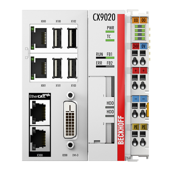
Connection and cabling Connection and cabling EtherCAT connection The latest generation of Embedded PCs can be ordered with the optional EtherCAT slave interface (B110). The optional interface B110 is identified as X300 on the devices and has as black border to identify it. The incoming EtherCAT signal is connected to the upper port of the X300 interface. -
Page 12: Cabling
Use PUR cables in robust industrial quality. Due to their mechanical properties and shielding, these cables are suitable for industrial environments. Do not use ordinary office cables. Suitable cables in robust industrial quality can be ordered from Beckhoff. EtherCAT from Master EtherCAT to Slave The incoming EtherCAT signal is connected to the upper port of the X300 interface. - Page 13 Connection and cabling Short description of the 10BaseT and 100BaseT cable types Twisted pair copper cable for star topologies, where the distance between two devices may not exceed 100 meters. Unshielded twisted pair This type of cable belongs to category 3, and is not recommended for use in an industrial environment. S/UTP Screened/unshielded twisted pair (screened with copper braid) Has a general screen of copper braid to reduce influence of external interference.
-
Page 14: Topology
Connection and cabling Topology EtherCAT offers free choice of topology and maximum wiring flexibility. The EtherCAT devices can be wired with or without switches, lines or tree topology. EtherCAT supports almost any topology. Addresses are assigned automatically, and an IP address does not have to be set separately. It is possible to operate up to 65.535 EtherCAT devices, with a maximum distance of 100 m between two devices. -
Page 15: Twincat Tabs
TwinCAT tabs TwinCAT tabs In TwinCAT, information and settings for the EtherCAT interface are added under tabs. The main TwinCAT tabs are described in this section. In addition, the section illustrates how the EtherCAT interface is displayed in the tree view under TwinCAT. The tree view and the tabs for a EtherCAT interface are identical under TwinCAT2 and TwinCAT3. - Page 16 PLC program. Double-click on a variable name in the tree view to open the link dialog. The linked signals are indicated by a small arrow on the signal symbol. Further information about TwinCAT can be found in the TwinCAT documentation on the Beckhoff website: www.beckhoff.de Version: 1.3...
-
Page 17: Ethercat Slave
TwinCAT tabs EtherCAT slave 4.2.1 General The General tab contains general information for an EtherCAT slave, including name, type and ID. Description Name of the EtherCAT device EtherCAT device type Here you can add a comment (e.g. notes relating to the system component) Here you can deactivate the EtherCAT device Number of the EtherCAT device The EtherCAT slave can be switched off via this tab. -
Page 18: Ethercat
TwinCAT tabs 4.2.2 EtherCAT General information about the EtherCAT slave is displayed on the EtherCAT tab. Description Name and type of the EtherCAT device. Product and revision number of the EtherCAT device. Auto increment address of the EtherCAT device. The auto increment address can be used for addressing each EtherCAT device in the communication ring through its physical position. - Page 19 TwinCAT tabs 4.2.3 This tab can be used for the distributed clock settings. The EtherCAT slave can be operated in FreeRun mode or DC Synchronous mode. Description Here you can change the settings for the Operation mode. You can choose between FreeRun and DC Synchronous mode.
-
Page 20: Process Data
TwinCAT tabs 4.2.4 Process data This tab indicates the configuration of the process data. The input and output data of the EtherCAT slave are represented as CANopen process data objects (PDO). Version: 1.3 CXxxxx-B110... - Page 21 TwinCAT tabs Description Lists the configuration of the sync manager (SM). If the EtherCAT device has a mailbox, SM0 is used for the mailbox output (MbxOut) and SM1 for the mailbox input (MbxIn). SM2 is used for the output process data (outputs) and SM3 for the input process data (inputs).
-
Page 22: Startup
TwinCAT tabs 4.2.5 Startup The Startup tab is displayed if the EtherCAT slave has a mailbox and supports the CANopen over EtherCAT (CoE) or Servo drive over EtherCAT protocol. This tab indicates which download requests are sent to the mailbox during startup. It is also possible to add new mailbox requests to the list display. -
Page 23: Ethercat Slave (Slave Only)
TwinCAT tabs 4.2.6 EtherCAT slave (slave only) The EtherCAT Slave tab provides information such as the NetId of the EtherCAT slave. The functions Device State, Distributed Clocks and Explicit Device Identification can be activated on this tab. The Advanced Settings for the EtherCAT slave can also be accessed via this tab. Description Physical interface. -
Page 24: Parameterization And Commissioning
Parameterization and commissioning Parameterization and commissioning The EtherCAT slave can be configured with TwinCAT 2 or TwinCAT 3. The following sections describe the EtherCAT state machine and how to insert an EtherCAT slave in TwinCAT, create variables and activate the device status and the device identification. - Page 25 Parameterization and commissioning Operational (Op) Before the EtherCAT master switches the EtherCAT Slave from Safe-Op to Op, it must transmit already valid output data. In the Op state the slave copies the output data of the master to its outputs. Process data and mailbox communication is possible.
-
Page 26: Parameterization With Twincat 2
Parameterization and commissioning Parameterization with TwinCAT 2 This section illustrates how CANopen devices can be parameterized with the aid of TwinCAT 2. A total of three devices are used for the sample, including a CANopen master, to which two CANopen slaves are connected. - Page 27 Parameterization and commissioning 4. Type the host name or the IP address of the device into the Enter Host Name / IP box and press [Enter]. 5. Mark the device found and click on Add Route. The Logon Information window appears. 6.
-
Page 28: Appending An Ethercat Device
Parameterization and commissioning 5.2.2 Appending an EtherCAT device Once you have selected an EtherCAT device as target system, you can add the EtherCAT device in the tree view in TwinCAT. These operations can be used to add an EtherCAT master or EtherCAT slave in the tree view. Prerequisites for this step: •... -
Page 29: Creating Variables
Parameterization and commissioning 5.2.3 Creating variables The EtherCAT slave has a simple structure and consists of inputs, outputs and InfoData. In TwinCAT you can add process data to the inputs or outputs, which can later be linked to variables from the PLC program. This section describes how to create such data. - Page 30 Parameterization and commissioning Data structure sample byTest: BYTE; udTest: UDINT; ARM address ARM variable Address x86 ARM variable Byte Offset 0 Byte Byte Offset 0 BYTE Byte Offset 4 UDINT Byte Offset 1 UDINT Sum: 8 byte Sum: 5 byte You can determine the length of a data structure on both systems using the command SIZEOF.
-
Page 31: Enable Device Status
Parameterization and commissioning 5.2.4 Enable device status The device status function indicates whether the EtherCAT slave is in operation and exchanges data. The function can be used for diagnostic purposes and provides important information about the EtherCAT slave. The device status is disabled by default and has to be enabled in TwinCAT, before the slave status can be displayed. -
Page 32: Enable Device Identification
Parameterization and commissioning 5.2.5 Enable device identification The EtherCAT Hot Connect functionality enables preconfigured sections to be removed from or added to the data traffic before startup or during operation. This can be done by disconnecting/connecting the communication path, turning the device on/off or other measures. This function is particularly advantageous for applications in which frequent topology changes are required. -
Page 33: Creating A Plc Project
Parameterization and commissioning 5.2.6 Creating a PLC project Use PLC Control to create a PLC project. The next steps describe how to create a PLC project in TwinCAT and add it in the tree view. Prerequisites for this step: • An Embedded PC, added in TwinCAT. Create a PLC project as follows: 1. - Page 34 Parameterization and commissioning Adding a PLC project The PLC project can be added in the System Manager. The newly created variables from a PLC project are integrated in the System Manager and can be linked with the inputs and outputs of the hardware. Prerequisites for this step: •...
-
Page 35: Linking Variables
Parameterization and commissioning 5.2.7 Linking variables Once the PLC project was successfully added in the System Manager, you can link the newly created input and output variables from the PLC project with the inputs and outputs of your devices. Prerequisites for this step: •... -
Page 36: Load Configuration To Cx
Parameterization and commissioning 5.2.8 Load configuration to CX Once all variables are linked, the configuration can be saved and loaded on the CX. This has the advantage that the PLC project is loaded and started automatically when the CX is switched on. The start of the previously created PLC project can thus be automated. - Page 37 Parameterization and commissioning 7. In the tree view on the left click on PLC – Configuration, then on the PLC Settings (Target) tab. 8. Select the Start PLC under Boot Project and click on Apply. 9. Start PLC Control and open the PLC project. 10.
-
Page 38: Parameterization With Twincat 3
Parameterization and commissioning Parameterization with TwinCAT 3 This section illustrates how CANopen devices can be parameterized with the aid of TwinCAT 3. A total of three devices are used for the sample, including a CANopen master, to which two CANopen slaves are connected. - Page 39 Parameterization and commissioning 4. Type the host name or the IP address of the device into the Enter Host Name / IP box and press [Enter]. 5. Mark the device found and click on Add Route. The Logon Information window appears. Enter the user name and password for the CX in the User Name and Password fields and click OK.
-
Page 40: Appending An Ethercat Device
Parameterization and commissioning 5.3.2 Appending an EtherCAT device Once you have selected an EtherCAT device as target system, you can add the EtherCAT device in the tree view in TwinCAT. These operations can be used to add an EtherCAT master or EtherCAT slave in the tree view. Prerequisites for this step: •... -
Page 41: Creating Variables
Parameterization and commissioning 5.3.3 Creating variables The EtherCAT slave has a simple structure and consists of inputs, outputs and InfoData. In TwinCAT you can add process data to the inputs or outputs, which can later be linked to variables from the PLC program. This section describes how to create such data. - Page 42 Parameterization and commissioning Process data with structures In order to save a large number of links it is a good idea to use a data structure to save data that you wish to exchange. Note that data structures with different variables are processed differently on an x86 system and an ARM processor.
-
Page 43: Enable Device Status
Parameterization and commissioning 5.3.4 Enable device status The device status function indicates whether the EtherCAT slave is in operation and exchanges data. The function can be used for diagnostic purposes and provides important information about the EtherCAT slave. The device status is disabled by default and has to be enabled in TwinCAT, before the slave status can be displayed. -
Page 44: Enable Device Identification
Parameterization and commissioning 5.3.5 Enable device identification The EtherCAT Hot Connect functionality enables preconfigured sections to be removed from or added to the data traffic before startup or during operation. This can be done by disconnecting/connecting the communication path, turning the device on/off or other measures. This function is particularly advantageous for applications in which frequent topology changes are required. -
Page 45: Creating A Plc Project
Parameterization and commissioning 5.3.6 Creating a PLC project The next steps describe how to create a PLC project in TwinCAT and add it in the tree view. Prerequisites for this step: • A newly created TwinCAT XAE project. Create a PLC project as follows: 1. - Page 46 Parameterization and commissioning 5. In the tree view right-click on the PLC project, then click on Build in the context menu. ð You have successfully created a PLC project and added the project in TwinCAT. A PLC instance with the variables for the inputs and outputs is created from the PLC project.
-
Page 47: Linking Variables
Parameterization and commissioning 5.3.7 Linking variables Once the PLC project was successfully added in the System Manager, you can link the newly created input and output variables from the PLC project with the inputs and outputs of your hardware. Prerequisites for this step: •... -
Page 48: Load Configuration To Cx
Parameterization and commissioning 5.3.8 Load configuration to CX Once variables are linked, the configuration can be saved and loaded on the CX. This has the advantage that the PLC project is loaded and started automatically when the CX is switched on. The start of the previously created PLC project can thus be automated. - Page 49 Parameterization and commissioning 7. In the context menu click on Autostart Boot Project. The setting is selected 8. Right-click on the project folder in the tree view. 9. In the context menu click on Auto Save to Target as Archive. The setting is selected.
-
Page 50: Error Handling And Diagnostics
Error handling and diagnostics Error handling and diagnostics Diagnostic LEDs These LEDs are used for fieldbus diagnostics. Display Display State Description Link/Act No connection on the EtherCAT strand green linked EtherCAT device connected Link/Act flashing active Communication with EtherCAT device Link/Act Display Color... -
Page 51: Device Status
Error handling and diagnostics Device Status The device status function indicates whether the EtherCAT slave is in operation and exchanges data. The information can be used for EtherCAT slave diagnostics. The device status function must be enabled in TwinCAT in order to display the corresponding variables in the tree view. -
Page 52: State
Error handling and diagnostics State In the tree view, input variables are consolidated under the Info Data menu item, which provide information about an EtherCAT slave. The State variable indicates the EtherCAT status of the EtherCAT slave. In addition, the variable provides general information about the slave. -
Page 53: Wcstate
Error handling and diagnostics WcState The variables under WcState (working counter state) use a working counter to indicate whether the EtherCAT slave takes part in the cyclic process data traffic successfully and error-free. The variable WcState of an EtherCAT slaves should therefore always be evaluated. The variables are only displayed, if the EtherCAT slave is added via an EtherCAT master in TwinCAT. -
Page 54: Appendix
Appendix Appendix Accessories Connector Item number Description ZS1090-0003 Ethernet/EtherCAT RJ-45 plug connector, 4-pin, IP 20, field- configurable ZS1090-0005 Ethernet/EtherCAT RJ-45 plug connector, 8-pin, IP 20, field- configurable Cable Item number Description ZB9010 Industrial Ethernet/EtherCAT cable, fixed installation, CAT 5e, 4-wires ZB9020 Industrial Ethernet/EtherCAT cable, suitable for drag chains, CAT 5e, 4-core... -
Page 55: Certifications
All products of the Embedded PC family are CE, UL and EAC certified. Since the product family is continuously developed further, we are unable to provide a full listing here. The current list of certified products can be found at www.beckhoff.com. FCC Approvals for the United States of America... -
Page 56: Support And Service
Beckhoff's branch offices and representatives Please contact your Beckhoff branch office or representative for local support and service on Beckhoff products! The addresses of Beckhoff's branch offices and representatives round the world can be found on her internet pages: http://www.beckhoff.com You will also find further documentation for Beckhoff components there. - Page 58 Beckhoff Automation GmbH & Co. KG Hülshorstweg 20 33415 Verl Germany Phone: +49 5246 9630 info@beckhoff.com www.beckhoff.com...
Need help?
Do you have a question about the CX B110 Series and is the answer not in the manual?
Questions and answers