
Related Manuals for Beckhoff FC2001


Summary of Contents for Beckhoff FC2001
- Page 1 Documentation FC2001 and FC2002 Lightbus PCI Interface Cards Version: Date: 2017-10-26...
-
Page 3: Table Of Contents
DPRAM (online) tab........................ 17 Appending further components..................... 17 5 Diagnostics .............................. 21 Diagnostics via the System Manager ................... 21 Status and diagnostic inputs...................... 23 Diagnostics with function blocks .................... 25 6 Appendix .............................. 27 Support and Service ........................ 27 FC2001 and FC2002 Version: 2.0... - Page 4 Table of contents Version: 2.0 FC2001 and FC2002...
-
Page 5: Foreword
The TwinCAT Technology is covered, including but not limited to the following patent applications and patents: EP0851348, US6167425 with corresponding applications or registrations in various other countries. ® EtherCAT is registered trademark and patented technology, licensed by Beckhoff Automation GmbH, Germany Copyright © Beckhoff Automation GmbH & Co. KG, Germany. -
Page 6: Safety Instructions
All the components are supplied in particular hardware and software configurations appropriate for the application. Modifications to hardware or software configurations other than those described in the documentation are not permitted, and nullify the liability of Beckhoff Automation GmbH & Co. KG. Personnel qualification This description is only intended for trained specialists in control, automation and drive engineering who are familiar with the applicable national standards. -
Page 7: Product Overview
Product overview Lightbus System Description System description for FC200x / EL6720 The following system description is applicable both for the Beckhoff Lightbus PCI interface card FC200x and for the Lightbus master terminal EL6720. Note The Lightbus consists of the Lightbus PCI interface card (in short Lightbus card) and an optical fiber-based fieldbus. -
Page 8: Fig. 2 Lightbus Telegram Structure
• Data: Input, output and flags • Communication: Initialization, testing, analysis and configuration of the Beckhoff Lightbus • Process control: Updating the Process Image The DPRAM of the Lightbus cards requires 4 kB per channel in the address space of the PC. -
Page 9: Hardware
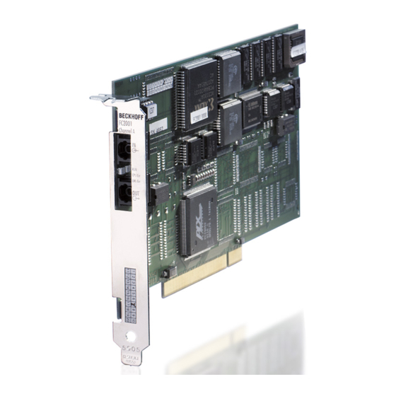
PC, and therefore provides access for TwinCAT to the sensors and actuators in the automation process. The FC2002 Lightbus card can operate two optical fiber rings. In logical terms, it behaves like two FC2001 cards, i.e. the FC2002 contains two sets of components for the optical fiber ring. Lightbus card components Fig. 3: Lightbus card components... -
Page 10: Fig. 4 Status Displays
◦ If the Run LED is also on, a program error is present that may potentially be rectified through a hardware reset. 3. Run: ◦ If only the green Run LED is on, the FC200x was initialized without errors and is ready for operation. Version: 2.0 FC2001 and FC2002... -
Page 11: Technical Data
Lightbus channel Interrupts Triggering of 2 IRQs is possible Supply voltage (PCI bus) 5 V Current consumption (PCI bus) typically 385 mA typically 700 mA Permissible ambient temperature 0°C ... +55°C during operation Dimensions approx. 106 mm x 187 mm FC2001 and FC2002 Version: 2.0... -
Page 12: Installation
Lightbus cards, particularly if several Lightbus cards are installed. Installation of the PCI driver After installation of the Beckhoff Lightbus card, Windows 2000, for example, comes up with the following message during start-up: Fig. 5: Installation of the PCI driver – new hardware found The PCI driver for the Lightbus card is supplied with the Beckhoff TwinCAT automation software. -
Page 13: Fig. 6 Installation Of The Pci Driver - Resource Settings
Installation Fig. 6: Installation of the PCI driver – resource settings FC2001 and FC2002 Version: 2.0... -
Page 14: Configuration By Means Of The Twincat System Manager
Example: The two Lightbus channels of a FC2002 are displayed as device 1 and device 2. Fig. 8: Configuration using the System Manager – new I/O devices found I/O devices may be renamed via a slow double-click (e.g. renaming to FC2002 Lightbus A). Version: 2.0 FC2001 and FC2002... -
Page 15: Fc200X Tab
Further properties of the I/O devices can be found under their respective entries. Use the mouse to select a Lightbus channel (in the example FC 2002 Lightbus A) and click on the FC200x tab. Fig. 10: TwinCAT System Manager – FC200x tab FC2001 and FC2002 Version: 2.0... - Page 16 System Manager. If individual CDLs are to be reserved for special applications, they should be marked here. They are then no longer available for the TwinCAT System Manager. Firmware Indicates the firmware version of the Lightbus card. For older Lightbus cards (e.g. C1220) only Found is displayed. Version: 2.0 FC2001 and FC2002...
-
Page 17: Dpram (Online) Tab
Further components can be added via the right mouse button. Appending I/O modules Right-click on the I/O device (FC2002 Lightbus A in the example) to which you would like to add I/O modules and select the menu item Append Box. FC2001 and FC2002 Version: 2.0... -
Page 18: Fig. 12 Twincat System Manager - Appending Further Components
Configuration by means of the TwinCAT System Manager Fig. 12: TwinCAT System Manager – appending further components The TwinCAT System Manager now offers various I/O modules for selection. Version: 2.0 FC2001 and FC2002... -
Page 19: Fig. 13 Twincat System Manager - Appending A Bus Coupler
All I/O modules of the Lightbus configuration should be added consecutively to the configuration tree in this way. The resulting order has to match the physical order of the I/O modules in the optical fiber ring! FC2001 and FC2002 Version: 2.0... - Page 20 Configuration by means of the TwinCAT System Manager Please refer to the Beckhoff Information System for details of how to link the inserted I/O modules with the process image of the Lightbus card. Version: 2.0 FC2001 and FC2002...
-
Page 21: Diagnostics
Any broken lines are also detected and located. Fig. 15: TwinCAT System Manager – online reset Optical fiber break test Initiates a break test on the optical fiber ring. FC2001 and FC2002 Version: 2.0... -
Page 22: Fig. 16 Break Test
Diagnostics Fig. 16: Break test Fig. 17: The test returns the number of I/O modules (boxes) found in the ring Fig. 18: or, in the event of an error, the location of the break point. Version: 2.0 FC2001 and FC2002... -
Page 23: Status And Diagnostic Inputs
In the event of an error this contains the code of the function that has triggered the error, e.g.: 0x01 Optical fiber reset 0x02 Code word request 0x05 Optical fiber attenuation test (intensity check) 0x06 Count I/O modules (counting boxes) 0x07 Test I/O module addresses (address check) 0x09 Software reset FC2001 and FC2002 Version: 2.0... - Page 24 Telegram with logically incorrect content (AD not equal D3) received. This counter does not increment the checksum error! AddressCheckModule Module address for errors during internal address check (DPRAM offset: 0xEEC): Contains the address of the I/O module (box) that caused the error. Version: 2.0 FC2001 and FC2002...
-
Page 25: Diagnostics With Function Blocks
The function blocks IOF_LB_BreakLocationTest and IOF_GetBoxCount are described as examples below. Detailed documentation about these and further function blocks can be found in the Beckhoff Information System, which is supplied with the TwinCAT automation software and is also included on the Products &... -
Page 26: Fig. 21 Function Block Iof_Getbox_Count
The module number before the receiver input in front of which the break location has been detected. Further information for the use of this function block can be found in the Beckhoff Information System. IOF_GetBoxCount The function block IOF_GetBoxCount can be used to determine the number of configured and active I/O boxes (modules) of an I/O device (fieldbus card). -
Page 27: Appendix
Beckhoff's branch offices and representatives Please contact your Beckhoff branch office or representative for local support and service on Beckhoff products! The addresses of Beckhoff's branch offices and representatives round the world can be found on her internet pages: http://www.beckhoff.com You will also find further documentation for Beckhoff components there. - Page 28 ............Fig. 19 TwinCAT System Manager – status and diagnostic inputs ............Fig. 20 Function block IOF_LB_BreakLocationTest ................Fig. 21 Function block IOF_GetBox_Count ..................... Version: 2.0 FC2001 and FC2002...
Need help?
Do you have a question about the FC2001 and is the answer not in the manual?
Questions and answers