Table of Contents
Advertisement
Advertisement
Table of Contents

Subscribe to Our Youtube Channel
Related Manuals for Smartgen HGM4100LT


Summary of Contents for Smartgen HGM4100LT
- Page 1 HGM4100LT GENSET CONTROLLER USER MANUAL SMARTGEN (ZHENGZHOU) TECHNOLOGY CO., LTD.
- Page 2 SmartGen Technology at the address above. Any reference to trademarked product names used within this publication is owned by their respective companies. SmartGen Technology reserves the right to change the contents of this document without prior notice. Table 1 Software Version Date...
-
Page 3: Table Of Contents
HGM4100LT GENSET CONTROLLER USER MANUAL CONTENTS 1 OVERVIEW .............................. 5 2 PERFORMANCE AND CHARACTERISTICS ..................5 3 SPECIFICATION OPERATION ....................... 7 4 OPERATION ............................8 4.1 KEY FUNCTION ..........................8 4.2 CONTROLLER PANEL ........................9 4.3 AUTO START/STOP OPERATION ....................10 4.4 MANUAL START/STOP OPERATION .................. - Page 4 HGM4100LT GENSET CONTROLLER USER MANUAL 13.13 MTU ADEC(SAM module) ......................45 13.14 PERKINS ............................ 45 13.15 SCANIA ............................45 13.16 VOLVO EDC3 ..........................46 13.17 VOLVO EDC4 ..........................46 13.18 VOLVO-EMS2 ..........................46 13.19 YUCHAI ............................47 13.20 WEICHAI ............................ 47 14 FAULT FINDING ............................
-
Page 5: Overview
RS485 interface) via PC. Because of the characteristics of compact structure, simple wiring connection and high reliability, it can be widely used in all types of automatic genset control system. PERFORMANCE AND CHARACTERISTICS HGM4100LT: it is used for single unit automation and genset auto Start/Stop control by remote start signals. Main characteristics: ... - Page 6 HGM4100LT GENSET CONTROLLER USER MANUAL Output percentage with loading Overvoltage, undervoltage, overfrequency, underfrequency, overcurrent, overpower functions for generating; Precisely collecting all kinds of parameters for the generator: Temp. ° C/° F Oil Pressure kPa/psi/bar all be displayed Fuel Level...
-
Page 7: Specification Operation
HGM4100LT GENSET CONTROLLER USER MANUAL SPECIFICATION OPERATION Table 2 Technical Parameters Items Contents Operating Voltage DC8.0V to DC35.0V, Continuous Power Supply. <3W (standby ≤2W) Power Consumption AC Gen Voltage Input: 3Phase 4Wire 15V AC - 360 V AC (ph-N) 3Phase 3Wire... -
Page 8: Operation
HGM4100LT GENSET CONTROLLER USER MANUAL OPERATION KEY FUNCTION Table 3 Key Function Descriptions Icon Function Description Stop the running generator in auto/manual mode; Under alarm status, press the button can remove the alarm; In stop mode, press and hold the button for 3 seconds and it can Stop/ Reset test the indicator lights (lamp test);... -
Page 9: Controller Panel
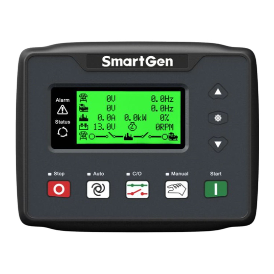
HGM4100LT GENSET CONTROLLER USER MANUAL CONTROLLER PANEL Fig.1 HGM4100LT Front Panel Indication NOTE: Illustration for some of indicator lights: Alarm Indicators: slowly flash when warning alarms; fast flash when shutdown alarms; light is off when none alarms. Status Indicators: Light is off when genset is standby; flash once per second during startup or shutdown; it is always on when it is normal running. -
Page 10: Auto Start/Stop Operation
HGM4100LT GENSET CONTROLLER USER MANUAL AUTO START/STOP OPERATION Press , and the indicator besides is on, which means the genset is in auto start mode. Start Sequence: When the remote start input is active, LCD displays countdown and it enters “Start Delay”;... -
Page 11: Manual Start/Stop Operation
HGM4100LT GENSET CONTROLLER USER MANUAL MANUAL START/STOP OPERATION , and the controller shall enter “Manual mode”. The manual mode indicator is on. Then Press press and start the genset. It can automatically judge whether crank disconnection is successful and it can accelerate to high speed running automatically. It can effectively protect and stop if high water temperature, low oil pressure, over speed, abnormal voltage etc. -
Page 12: Protection
HGM4100LT GENSET CONTROLLER USER MANUAL PROTECTION WARNINGS When the controller detects the warning signals, it shall only give alarm and not stop the genset. Besides, LCD displays the warning information. Table 4 Warning Types Type Description When the sample temperature got by the temperature sensor is higher... - Page 13 HGM4100LT GENSET CONTROLLER USER MANUAL Type Description When the controller detects that the engine speed is 0 and the delay is 0, Loss Speed it will initiate a warning alarm and the corresponding alarm information Signal will be displayed on LCD.
- Page 14 HGM4100LT GENSET CONTROLLER USER MANUAL Type Description When genset running time has exceeded the users-set maintenance time and the maintenance action is “Warn”, it will initiate a warning alarm Maintenance and the corresponding alarm information will be displayed on LCD. The maintenance alarm will reset if the action is selected “Inactive”.
-
Page 15: Shutdown Alarm
HGM4100LT GENSET CONTROLLER USER MANUAL SHUTDOWN ALARM When the controller detects shutdown alarm, it will open the breaker immediately and stop the engine. At the same time alarm type shall be displayed. Table 5 Shutdown Alarms Type Description When the controller detects emergency stop signals, it will send... - Page 16 HGM4100LT GENSET CONTROLLER USER MANUAL Type Description than the set stop value, it will send stop alarm signals and the corresponding alarm information will be displayed on LCD. When controller detects oil pressure is lower than the set value, Low Oil Pressure it will send stop signals and the corresponding alarm information will be displayed on LCD.
- Page 17 HGM4100LT GENSET CONTROLLER USER MANUAL Type Description Open sensor port, is open circuit, and the open circuit action in parameter configuration is selected “shutdown”, it will send stop alarm signals and the corresponding alarm information will be displayed on LCD.
-
Page 18: Wiring Connection
HGM4100LT GENSET CONTROLLER USER MANUAL WIRING CONNECTION HGM4100LT controller back panel is as bellows: Fig.3 HGM4100LT Back Panel Table 6 Terminal Wiring Connection Cable Function Remarks Size 2.5mm Connected with negative of starter battery; Connected with positive of starter battery; If wire 2.5mm... - Page 19 HGM4100LT GENSET CONTROLLER USER MANUAL Cable Function Remarks Size B+ output is supplied by Aux. Output 3 1.0mm terminal 2 with rated 1A. B+ output is supplied by Aux. Output 4 1.0 mm terminal 2 with rated 1A. Aux. Input 1 1.0mm...
-
Page 20: Scopes And Definitions Of Programmable Parameters
HGM4100LT GENSET CONTROLLER USER MANUAL Cable Function Remarks Size C-phase monitoring Externally connected to CT secondary coil (5A 1.5mm input rated); CT COM 1.5mm Reference to Installation Instruction NOTE: USB ports in controller back panel are programmable parameter ports, and users can directly configure the controller via PC. - Page 21 HGM4100LT GENSET CONTROLLER USER MANUAL Items Range Default Description detecting engine speed; Abnormal Alarm delay for generating voltage over (0-20.0)s 10.0 Delay high/low; When generator voltage has exceeded the set value and the “Gen abnormal delay” has Gen Over Voltage...
- Page 22 HGM4100LT GENSET CONTROLLER USER MANUAL Items Range Default Description and not shutdown of the generator. (80-140)º C The values correspond to the function settings Flexible Sensor (0-400)kPa of 23 (Temperature sensor), 24 (Oil pressure Values sensor) and 25 (Level sensor) respectively.
- Page 23 HGM4100LT GENSET CONTROLLER USER MANUAL Items Range Default Description Factory default: Low Oil Pressure Alarm input. Digital Input 2 (0-31) For details please see Table 9. Digital Input (0-1) Factory default: active when it is closed; Active Digital Input (0-20.0)s Delay Factory default: Remote Start input;...
- Page 24 HGM4100LT GENSET CONTROLLER USER MANUAL Items Range Default Description warning alarm is initiated. For details please see 64,65,66 Setting Items. (0-3) Voltage Input 0: 3P4W; 1: 2P3W; 2: 1P2W; 3: 3P3W Temp. Sensor (0-12) SGX; For details please see Table 10.
- Page 25 HGM4100LT GENSET CONTROLLER USER MANUAL Items Range Default Description When generator frequency exceeds the pre-set Over Freq (0-75.0)Hz 55.0 value, gen over frequency warning signals will Warning be sent. When generator frequency is below the pre-set Under Freq (0-75.0)Hz 42.0...
- Page 26 HGM4100LT GENSET CONTROLLER USER MANUAL Items Range Default Description Auto Start Inhibit Set (0-1) 0: Enabled disabled 1: Enabled (0-2) Cycle options: 0:monthly 1:Weekly 2:Daily (1-31) Day(Cycle options: 0: monthly active) (0-7) Cycle Auto Start Week(Cycle options: 0: weekly active)
- Page 27 HGM4100LT GENSET CONTROLLER USER MANUAL fuel level alarm input signal is active, the controller shall only send low fuel level warning signal and not shutdown the genset; Multiplex input port can choose any one of digital input type and sensor and it is active after configuration. e.g.
-
Page 28: Definable Contents Of Programmable Output Ports
HGM4100LT GENSET CONTROLLER USER MANUAL DEFINABLE CONTENTS OF PROGRAMMABLE OUTPUT PORTS Table 8 Definable Contents of Programmable Output Ports 1~5 Items Description Output port is deactivated when “Not Used” is selected. Not Used It includes all shutdown alarms and warning alarms. When there Common Alarm is warning alarm only, it is not self-lock;... -
Page 29: Defined Contents Of Configurable Input Ports
HGM4100LT GENSET CONTROLLER USER MANUAL Items Description When warning and shutdown alarms appear, audible alarm output Audible Alarm is fixed as 300s, during the time whether press any key on the panel or Alarm Mute input is active, it can remove the alarm. - Page 30 HGM4100LT GENSET CONTROLLER USER MANUAL Items Description When this input is active in auto mode, genset starts automatically Remote Start and loads after running. Otherwise, genset will stop automatically if it is inactive. Fuel Level Warning Connected to digital input port of sensor, if this input is active, controller will send warning alarm signal.
-
Page 31: Selection Of Sensors
HGM4100LT GENSET CONTROLLER USER MANUAL SELECTION OF SENSORS Table 10 Sensor Selection Item Description Remark 0 Not used 1 User Configured (Resistor type Curve) 2 VDO 3 SGH Users-defined 4 SGD Temperature resistance type range is 5 CURTIS 0Ω-999.9Ω; default is... -
Page 32: Conditions Of Crank Disconnection Selection
HGM4100LT GENSET CONTROLLER USER MANUAL CONDITIONS OF CRANK DISCONNECTION SELECTION Table 11 Crank Disconnection Condition Selection Set Contents Speed Gen frequency Speed + Gen frequency Speed +Oil pressure Gen frequency + Oil pressure Speed + Gen frequency + Oil pressure... -
Page 33: Parameter Settings
HGM4100LT GENSET CONTROLLER USER MANUAL PARAMETER SETTING CONTROLLER PARAMETER SETTING Start the controller, and then press to enter the parameter setting menu. Menu items are as follows: Set Parameters Information Set Language/语言 Event Log Maintenance When password “0318” is inputted, all parameter items in Table 7 can be set. If the password “0318”... -
Page 34: Controller Information
Password is needed to be inputted at the moment of entering maintenance interface. Default value is a 0 (this password is changeable, but it is needed to contact with SmartGen service personnel or sales personnel.). Setting maintenance parameters will refresh maintenance time. -
Page 35: Sensor Setting
HGM4100LT GENSET CONTROLLER USER MANUAL SENSOR SETTING ─ If a sensor is needed to be changed again, the sensor curve will be transferred into the standard value. For example, if the default temperature sensor is SGH (120° C resistor type), the sensor curve is SGH curve (120°... -
Page 36: Commissioning
If this is not the case, please refer to this manual and check ATS control wire connections. — If there is any other question, please contact SmartGen’s service as soon as possible. HGM4100LT Genset Controller 2019-01-28 Version1.0... -
Page 37: Typical Application
HGM4100LT GENSET CONTROLLER USER MANUAL 11 TYPICAL APPLICATION Fig. 4 HGM4100LT Typical Application Fig. 5 HGM4100LT Typical Application HGM4100LT Genset Controller 2019-01-28 Version1.0 Page 37 of 48... -
Page 38: Installation
HGM4100LT GENSET CONTROLLER USER MANUAL Fig. 6 2-Phase 3-Wire Connection Diagram Fig. 7 Single Phase 2-Wire Connection Diagram Note: Expansion relays with high capacity in start and fuel outputs are recommended. INSTALLATION 12.1 FIXING CLIPS The controller is panel built-in design; and it is fixed by clips for installation. - Page 39 HGM4100LT GENSET CONTROLLER USER MANUAL HGM4100LT controller can suit wide range of battery voltage DC(8~35)V. Negative of battery must be connected with the engine shell. Diameter of wire which connects power supply with battery must be over 2.5mm . If floating charge is configured, please firstly connect output wires of the charger to battery’s positive and negative directly, then connect wires from battery’s positive and negative to...
-
Page 40: Connection Of Controller And Engine With J1939
HGM4100LT GENSET CONTROLLER USER MANUAL CONNECTIONS OF CONTROLLER WITH ENGINE J1939 13.1 CUMMINS ISB/ISBE Table13 Connector B Terminals of controller Connector B Remark Set configurable output 1 as “Fuel Relay Programmable output port 1 Output”; Start relay output Connected with starter coil directly;... -
Page 41: Cummins Qsm11 (Import)
HGM4100LT GENSET CONTROLLER USER MANUAL 13.3 CUMMINS QSM11 (import) It is suitable for CM570 engine control mode. Engine type is QSM11 G1, QSM11 G2. Table 17 C1 Connector Terminals of controller C1 connector Remark Set configurable output 1 as “Fuel Relay Output”;... -
Page 42: Cummins Gcs-Modbus
HGM4100LT GENSET CONTROLLER USER MANUAL 13.5 CUMMINS GCS-MODBUS It is suitable for GCS engine control module. Read engine information by using RS485-MODBUS. Engine types are QSX15, QST30, QSK23 / 45/60/78 and so on. Table 21 D-SUB Connector 06 Terminals of controller... -
Page 43: Detroit Diesel Ddec Iii / Iv
HGM4100LT GENSET CONTROLLER USER MANUAL Table 24 Engine OEM Connector Terminals of controller engine OEM connector Remark Programmable output1 Start relay output Connected to starter coil directly; Programmable output 2 16&41 Set it as idling speed control, normal close output; making 16 connected to 41 during high-speed running via external expansion relay;... -
Page 44: John Deere
HGM4100LT GENSET CONTROLLER USER MANUAL 13.10 JOHN DEERE Table 27 21 Pins Connector Terminals of controller 21 pins connector Remark Set configurable output 1 as “Fuel Relay Programmable output1 G, J Output”; Start relay output CAN communication shielding line; CAN_SCR Using impedance 120Ω... -
Page 45: Mtu Adec(Sam Module)
HGM4100LT GENSET CONTROLLER USER MANUAL 13.13 MTU ADEC(SAM module) It is suitable for MTU engine with ADEC (ECU7) and SAM module. Table 31 ADEC (X1 port) Terminals of controller ADEC (X1port) Remark Set configurable output 1 as “Fuel Relay Programmable output1 X1 43 Output”;... -
Page 46: Volvo Edc3
HGM4100LT GENSET CONTROLLER USER MANUAL 13.16 VOLVO EDC3 It is suitable for engine type TAD1240, TAD1241, and TAD1242. Table 35 “Stand alone” Connector “Stand alone” connector Terminals of controller Remark Set configurable output 1 as “Fuel Relay Programmable output1 Output”;... -
Page 47: Yuchai
HGM4100LT GENSET CONTROLLER USER MANUAL Table 38 Engine CAN Port Engine’s CAN port Terminals of controller Remark ECU stop; Programmable output1 Set configurable output 1 as “ECU stop”; ECU power; Programmable output2 Set configurable output 2 as “ECU power”; Negative power;... -
Page 48: Fault Finding
HGM4100LT GENSET CONTROLLER USER MANUAL 14 FAULT FINDING Table 42 Fault and Solutions Symptoms Possible Solutions Check start batteries; Controller no response with power Check controller connection wirings; Check DC fuse; Check whether water/cylinder temperature is too high or not;...
Need help?
Do you have a question about the HGM4100LT and is the answer not in the manual?
Questions and answers