Table of Contents
Advertisement
Quick Links
Advertisement
Table of Contents

Related Manuals for Smartgen HGM501


Summary of Contents for Smartgen HGM501
- Page 1 HGM501 GENSET CONTROLLER USER MANUAL...
- Page 2 All rights reserved. No part of this publication may be reproduced in any material form (including photocopying or storing in any medium by electronic means or other) without the written permission of the copyright holder. SmartGen reserves the right to change the contents of this document without prior notice. Table 1- Version History Date...
- Page 3 This manual is suitable for HGM501 series controllers only. Clarification of signs used within this manual. Sign Explanation Concerns an operating procedure that needs highlighting. Note Indicates a procedure or practice, which, if not strictly observed, can Caution! result in damage of the equipment.
-
Page 4: Table Of Contents
7. CONFIGURABLE PARAMETERS ....................11 7.1. CONFIGURABLE PARAMETERS TABLE ..............11 7.2. PARAMETER CONFIGURATION ................... 13 8. COMMISSIONING ........................15 9. TYPICAL WIRING DIAGRAM ...................... 15 10. INSTALLATION ........................... 16 11. TROUBLESHOOTING ......................... 17 HGM501 Genset Controller User Manual Page 4 of 17... -
Page 5: Overview
HGM501 gen-set controller contains the microprocessor allows precise measurement of multiple parameters, which can be configured using controller front panel. With simple wiring, compact structure and high reliability, HGM501 can be widely used for data display and fault protection of a large number of diesel and petrol generator sets. -
Page 6: Technical Data
Storage Temperature (-30~+80)°C Protection level IP42 Apply AC1.5kV voltage between high voltage terminal and Insulation strength low voltage terminal; The leakage current is not more than 3mA within 1min. Weight 0.216kg HGM501 Genset Controller User Manual Page 6 of 17... -
Page 7: Operation
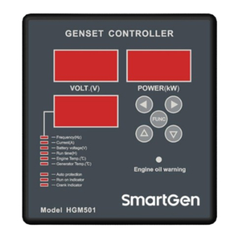
OPERATION 4.1. BUTTON DESCRIPTION Fig.1 – HGM501 Front Panel Table 3 – Key Functions Icon Function Description 1. In configuration menu, pressing this button enters setting or confirms; 2. During normal operation, press this button to switch to FUNCTION frequency display;... -
Page 8: Start/Stop Operation
During normal running of the gen-set, if low oil pressure signal is detected an last for over 2s, the set will be stopped. Manual stop Under any circumstances, if starter key is turned from ON to OFF position, it will lead to shutdown. HGM501 Genset Controller User Manual Page 8 of 17... -
Page 9: Auto Protection
16.5V, Nixie tube or LED display starts flashing, but shutdown protection is not initiated. NOTE: During Safety On delay, protection is disabled; after Safety On Delay, when voltage, frequency, overload, high temperature protection is initiated, fuel output deactivates. HGM501 Genset Controller User Manual Page 9 of 17... -
Page 10: Terminal
TERMINAL Fig.2 – HGM501 Back Panel Table 4 -Terminal Connections Description Terminal Function Wire size Remarks Generator Voltage L 1.0mm Generator Voltage N 1.0mm Load CT Secondary I (out) 1.0mm Current Transformer Secondary max current 62.5mA Load CT Secondary I* (in) 1.0mm... -
Page 11: Configurable Parameters
Fused and connected to start Fuel/Start Relay Common Port 2.5mm battery positive NOTE: Controller within the LINK port, which connect to SmartGen’s SG72 adapter. It is can be set or check genset’s real time data via PC software. CONFIGURABLE PARAMETERS 7.1. CONFIGURABLE PARAMETERS TABLE Table 5 –... - Page 12 Parts of parameters only can be configured via PC software, e.g. digital input port1. AC system selected "Double Rated Volts" means generator can output two kinds of rated voltage. TE4/TG4 sensor curve as bellow, Fig.3 – TE4/TG4 Sensor Curve HGM501 Genset Controller User Manual Page 12 of 17...
-
Page 13: Parameter Configuration
0 to 9 and to confirm and enter the next menu item; Engine temperature sensor type setting: when engine temperature indicator is on, HGM501 Genset Controller User Manual Page 13 of 17... - Page 14 CAUTION: Please change inner controller parameters (rated generator voltage, generator frequency etc.) only in standby mode, otherwise in can lead to shutdown or other abnormal condition. HGM501 Genset Controller User Manual Page 14 of 17...
-
Page 15: Commissioning
Then change start key position to START to start cranking. After the engine is fired, remove start key; voltage, frequency and power windows will show true collected values. For further information please contact SmartGen services. TYPICAL WIRING DIAGRAM Typical wiring diagram is shown below: Fig.4 –... -
Page 16: Installation
Fig.5 – Overall Dimensions and Panel Cutout Battery Voltage Input NOTE: HGM501 controller is suitable for 9-18 VDC battery voltage. Battery negative must be reliably connected to the enclosure of the engine. The controller power supply B+ and B- must be connected to battery positive and negative, and the wire size must not be less then 1.5mm2. -
Page 17: Troubleshooting
Check fuel return circuit and wiring Fail to start Check start battery Consult engine manual Check the wiring to the starter Starter motor does not respond Check start battery HGM501 Genset Controller User Manual Page 17 of 17...
Need help?
Do you have a question about the HGM501 and is the answer not in the manual?
Questions and answers