
Related Manuals for Smartgen HGM400N Series


Summary of Contents for Smartgen HGM400N Series
- Page 1 HGM400N SERIES (HGM410N/HGM420N) GENSET CONTROLLER USER MANUAL SMARTGEN (ZHENGZHOU) TECHNOLOGY CO.,LTD.
- Page 2 All rights reserved. No part of this publication may be reproduced in any material form (including photocopying or storing in any medium by electronic means or other) without the written permission of the copyright holder. Smartgen Technology reserves the right to change the contents of this document without prior notice. Version...
-
Page 3: Table Of Contents
HGM400N Series Genset Controller User Manual CONTENTS OVERVIEW ............................4 PERFORMANCE AND CHARACTERISTICS .................. 4 SPECIFICATION ..........................6 OPERATION ............................. 7 4.1 PUSHBUTTONS .......................... 7 4.2 INDICATOR LIGHT ........................8 4.3 AUTOMATIC START/STOP OPERATION .................. 9 4.4 MANUAL START/STOP OPERATION ..................10 4.5 EMERGENCY START ....................... -
Page 4: Overview
HGM400N Series Genset Controller User Manual OVERVIEW HGM400N series genset controllers integrate digitization, intelligentization and network technology which are used for genset automation and monitor control system of single unit to achieve automatic start/stop, data measurement, alarm protection and “three remote” (remote control, remote measuring and remote communication;... - Page 5 HGM400N Series Genset Controller User Manual and over power detection functions; Precision collect and display parameters about Engine, Temp. (WT) °C/°F Oil pressure (OP) kPa/psi/bar Fuel Level (FL) % remain fuel level L Engine Speed (RP) r/min Battery Voltage (VB)
-
Page 6: Specification
HGM400N Series Genset Controller User Manual SPECIFICATION Items Contents Working Voltage DC8. 0V to 35. 0V, Continuous Power Supply. <3W(Standby mode: ≤2W) Overall Consumption AC voltage Input: 3 Phase 4 Wire AC15V - AC360V (ph-N) 3 Phase 3 Wire AC30V - AC620V (ph-ph) -
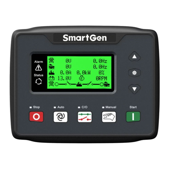
Page 7: Operation
HGM400N Series Genset Controller User Manual OPERATION 4.1 PUSHBUTTONS Icon Description Stop running generator in Auto/Manual mode; In case of alarm condition, pressing the button will reset alarm; In stop mode, pressing and holding the button for 3 seconds will test Stop/ Reset indicator lights (lamp test);... -
Page 8: Indicator Light
HGM400N Series Genset Controller User Manual 4.2 INDICATOR LIGHT HGM410N Panel Indicators HGM420N Panel Indicators Note: Partial indicator states Alarm Lamp: slowly blink when warning alarms; fast blink when shutdown alarms; won’t illuminate when there is no alarm. Status Lamp: won’t illuminate when genset stand by; blink 1 time in start or stop process and always illuminate when runs normally. -
Page 9: Automatic Start/Stop Operation
HGM400N Series Genset Controller User Manual 4.3 AUTOMATIC START/STOP OPERATION Auto mode is selected by pressing the button; a LED besides the button will illuminate to confirm the operation. Auto Start Sequence, HGM420N: when mains is abnormal (over/under voltage, loss of phase), enter into “Mains Abnormal Delay”... -
Page 10: Manual Start/Stop Operation
HGM400N Series Genset Controller User Manual 4.4 MANUAL START/STOP OPERATION HGM420N: Manual mode is selected by pressing the button; a LED besides the button will illuminate to confirm the operation. In this mode, press button to start the genset, it can automatically judge crank success and accelerate to high speed running. -
Page 11: Protection
HGM400N Series Genset Controller User Manual PROTECTION 5.1 WARNINGS Warnings are not shutdown alarms and do not affect the operation of the gen-set. Warning alarms does not lead to shutdown. The alarm information will be displayed on LCD. Warning alarms types are as follows:... - Page 12 HGM400N Series Genset Controller User Manual When the controller detects the low coolant level input is active, it will Low Coolant Level initiate a warning alarm and the corresponding alarm information will be displayed on LCD. When the controller detects that the temperature sensor is open circuit and the action select “Warn”, it will initiate a warning alarm and the...
- Page 13 HGM400N Series Genset Controller User Manual When the controller detects that the genset voltage has fallen below the Gen Under Volt pre-set value, it will initiate a warning alarm and the corresponding alarm information will be displayed on LCD. When the controller detects that the genset frequency has exceeded the...
-
Page 14: Shutdown Alarm
HGM400N Series Genset Controller User Manual 5.2 SHUTDOWN ALARM When controller detects shutdown alarm, it will send signal to open breaker and shuts down generator. The alarm information will be displayed on LCD. Shutdown alarms as following: Items Description When the controller detects that the emergency shutdown signal, it will... - Page 15 HGM400N Series Genset Controller User Manual Items Description alarm and the corresponding alarm information will be displayed on LCD. When the controller detects the low coolant level input is active, it will initiate Low Coolant Level a shutdown alarm and the corresponding alarm information will be displayed on LCD.
-
Page 16: Connections
HGM400N Series Genset Controller User Manual CONNECTIONS Compared with HGM420N, HGM410N has no Mains AC Voltage input terminals. The rear panel of HGM420N is as below. Description of terminal connections: Function Cable Size Description 2.5mm Connected with negative of starter battery. - Page 17 HGM400N Series Genset Controller User Manual Function Cable Size Description Connect to temperature/cylinder Engine Temp. Sensor 1.0mm resistance sensor. Connect pressure Oil Press Sensor 1.0mm resistance sensor. Outside connected to secondary coil of current Current IA 1.5mm transformer(rated 5A) Outside connected to secondary coil of current Current IB 1.5mm...
-
Page 18: Definition And Range Of Parameters
HGM400N Series Genset Controller User Manual DEFINITION AND RANGE OF PARAMETERS 7.1 PARAMETER CONTENTS AND RANGE Items Range Default Description Mains Normal Delay (0-3600)s The time from mains abnormal to normal or from normal to abnormal; suitable for ATS Mains Abnormal Delay (0-3600)s (automatic transfer switch). - Page 19 HGM400N Series Genset Controller User Manual Items Range Default Description stopped when “ETS time” is not 0. Pulse width of mains/generator switch on. Breaker Close Time (0-10)s When it is 0, means output constantly. Tooth number of the engine, for judging of...
- Page 20 HGM400N Series Genset Controller User Manual Items Range Default Description has expired. If the set value is 0, low oil pressure signal will not be sent (this only concerns pressure sensor and does not concern low oil pressure warning signal via...
- Page 21 HGM400N Series Genset Controller User Manual Items Range Default Description Aux. Output 3 (0-17) Factory default: Idle Control Aux. Output 4 (0-17) Factory default: Close Generator Aux. Output 5 (0-17) Factory default: Mains Closed Digital Input 1 (0-15) Factory default: High Temperature Input...
- Page 22 HGM400N Series Genset Controller User Manual Items Range Default Description 0: 3P4W; 1: 2P3W AC System (0-3) 2: 1P2W; 3: 3P3W Temp. Sensor Curve (0-12) SGX See Pressure Sensor Curve (0-12) SGX See 0: Digital Input 3 Multiplex Input 1...
- Page 23 HGM400N Series Genset Controller User Manual Items Range Default Description Percentage current is active. When this value is 0, warn alarm signal won’t be sent. When the temperature value of the external temperature sensor exceeds the set value, “High Temperature” timer is initiated. Detecting only after safety on delay has expired.
- Page 24 HGM400N Series Genset Controller User Manual Items Range Default Description (0-7) Week(0:weekly is active) (1-23)h Prohibit start time (h) (1-59)min Prohibit start time (min) (0-30000)min Duration 0 Inactive; 1 Warn; 2 Alarm Shutdown (0-2) Over power setting value (0-6000)kW Over power warn return...
-
Page 25: Programmable Output 1-5
HGM400N Series Genset Controller User Manual 7.2 PROGRAMMABLE OUTPUT 1-5 Items Description Output port is deactivated when “Not Used” is selected. Not Used Include all shutdown alarms and warning alarms. When there is Common Alarm warning alarm only, it is not self-lock; when a shutdown alarm occurs, it is self-lock until the alarm is reset. -
Page 26: Programmable Input 1-4 (Active When Connect Gnd (B-)
HGM400N Series Genset Controller User Manual 7.3 PROGRAMMABLE INPUT 1-4 (ACTIVE WHEN CONNECT GND (B-) Items Description Not Used High Temp. Input If these signals are active after safety on delay, shutdown alarm will be immediately initiated. Low OP Warning Input Auxiliary Warning Only warning and not stops if this input is active. -
Page 27: Sensor Select
HGM400N Series Genset Controller User Manual 7.4 SENSOR SELECT Item Content Description 0 Not used 1 User Defined Resistive Type 2 VDO 3 SGH 4 SGD 5 CURTIS Defined resistive range 6 DATCON Temp. Sensor (0~6000)Ω, default is SGX sensor. -
Page 28: Conditions Of Crank Disconnect
HGM400N Series Genset Controller User Manual 7.5 CONDITIONS OF CRANK DISCONNECT Content Magnetic pickup Generator Frequency Magnetic pickup + Generator Frequency Magnetic pickup + Oil pressure Generator Frequency + Oil pressure Generator Frequency + Magnetic pickup + Oil pressure Oil pressure There are 3 conditions to make starter separate with engine;... -
Page 29: Parameters Setting
HGM400N Series Genset Controller User Manual PARAMETERS SETTING Start the controller, then press to enter into the parameters setting menu as below: Set Parameters Information Language Event Log Maintenance Setting a) Parameters Setting “0318” can set all items in 7.1 during inputting password. When default password has been changed, it needs to input the same password with controller for parameter setting via PC software. -
Page 30: Sensor Setting
HGM400N Series Genset Controller User Manual setting interface. SENSOR SETTING 1) When reselect sensors, the sensor curve will be transferred into the standard value. For example, if temperature sensor is SGH (120°C resistor type), its sensor curve is SGH (120°C resistor type); if select the SGD (120°C resistor type), the temperature sensor curve is SGD curve. -
Page 31: Commissioning
When mains abnormal again, genset will start automatically and into normal running, send signal to make gens close, transfer ATS and make genset take load. If it not likes this, please check connections of ATS according to this manual. If there are any other questions, please contact SmartGen’s service. HGM400N Series Genset Controller 2017-04-21 Version 1.2... -
Page 32: Typical Application
HGM400N Series Genset Controller User Manual 11 TYPICAL APPLICATION HGM410N Typical wiring diagram HGM420N Typical wiring diagram HGM400N Series Genset Controller 2017-04-21 Version 1.2 Page 32 of 36... - Page 33 HGM400N Series Genset Controller User Manual Single Phase 2 Wire (HGM420N) 2 Phase 3 Wire (HGM420N) Suggestion: Expand relay with high capacity in start and fuel output is recommend. HGM400N Series Genset Controller 2017-04-21 Version 1.2 Page 33 of 36...
-
Page 34: Installation
12.2 OVERALL DIMENSION AND Panel CUTOUT Battery Voltage Input HGM400N series controller can suit for widely range of battery voltage DC(8~35)V. Negative of battery must be connected with the engine shell. The diameter of wire from power supply to battery must be over 2.5mm... - Page 35 AC Input HGM400N series controller must be connected to outside current transformer. And the current transformer’s secondary side current must be 5A. At the same time, the phases of current transformer and input voltage must correct. Otherwise, the collected current and active power maybe not correct.
-
Page 36: Fault Finding
HGM400N Series Genset Controller User Manual 13 FAULT FINDING Symptom Possible Remedy Check starting batteries; Controller response with Check controller connection wirings; power. Check DC fuse. Check the water/cylinder temperature is too high or not; Genset shutdown Check the genset AC voltage;...
Need help?
Do you have a question about the HGM400N Series and is the answer not in the manual?
Questions and answers