
Related Manuals for Smartgen HGM410E


Summary of Contents for Smartgen HGM410E
- Page 1 HGM400E Series Genset Controller (HGM410E/HGM420E) USER MANUAL Smartgen Technology...
- Page 2 Version Date Version Note 2013-08-17 Original release. Change “Auxiliary Input” to “Emergency Shutdown” 2013-08-28 This manual is suitable for HGM400E series controller only. Clarification of notation used within this publication. SYMBOL INSTRUCTION Highlights an essential element of a procedure to ensure NOTE correctness.
-
Page 3: Table Of Contents
HGM400E Series Automatic Control Module CONTENTS OVERVIEW..................5 PERFORMANCE AND CHARACTERISTICS ........6 SPECIFICATION ................8 OPERATION ..................9 4.1 PUSHBUTTONS ....................9 4.2 INDICATOR LIGHT ..................10 4.3 AUTOMATIC START/STOP OPERATION ............. 11 4.4 MANUAL START/STOP OPERATION ............12 PROTECTION ................ -
Page 4: Overview
HGM400E Series Automatic Control Module 1 OVERVIEW HGM400E series genset controllers integrate digitization, intelligentization and network technology which are used for genset automation and monitor control system of single unit to achieve automatic start/stop, data measure, alarm protection and “three remote” (remote control, remote measuring and remote communication; SG485 module must be fitted). -
Page 5: Performance And Characteristics
HGM410E: ASM (Automatic Start Module),it controls generator to start/stop by remote signal; HGM420E: AMF (Auto Mains Failure), updates based on HGM410E, moreover, has mains electric quantity monitoring and mains/generator automatic transfer control function, especially for automatic system composed by generator and mains. - Page 6 HGM400E Series Automatic Control Module Battery Voltage (VB) V (unit) Charger Voltage (VD) V (unit) Hours counter (HC): Max. 999999 hours Start times: Max.999999 times Protection: automatic start/stop of the genset, ATS(Auto Transfer Switch) control with perfect fault indication and protection function; ...
-
Page 7: Specification
HGM400E Series Automatic Control Module 3 SPECIFICATION Items Contents Working Voltage DC8. 0V to 35. 0V, Continuous Power Supply. <3W(Standby mode: ≤2W) Overall Consumption AC voltage Input: 3 Phase 4 Wire AC15V - AC360V (ph-N) 2 Phase 3 Wire AC15V - AC360V (ph-N) Single phase 2 Wire AC15V - AC360V (ph-N) 3 Phase 3 Wire... -
Page 8: Operation
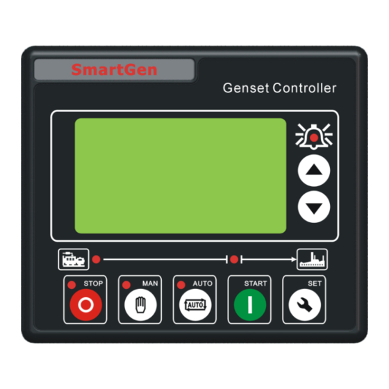
HGM400E Series Automatic Control Module 4 OPERATION 4.1 PUSHBUTTONS Stop running generator in Auto/Manual mode; In case of alarm condition, pressing the button will reset alarm; Stop/ Reset In stop mode, pressing and holding the button for 3 seconds will test indicator lights (lamp test); During stopping process, press this button again to stop generator immediately. -
Page 9: Indicator Light
HGM400E Series Automatic Control Module 4.2 INDICATOR LIGHT HGM410E Panel Indicators HGM420E Panel Indicators HGM400E Series Genset Controller ISSUE 2013-08-28 Version 1.1 Page 10 of 41... -
Page 10: Automatic Start/Stop Operation
1) HGM420E: during normal running process, if mains normal, enters into “Mains Normal Delay”. When mains indicator illuminates, “Stop Delay” begins. 2) HGM410E: When the “Remote Start” signal is removed, the Stop Delay is initiated. HGM400E Series Genset Controller ISSUE 2013-08-28 Version 1.1... -
Page 11: Manual Start/Stop Operation
Under Test Mode, after genset high speed normal running, no matter mains normal or not, load will be transferred to generator. 2) HGM410E: Manual mode is selected by pressing the button; a LED besides the button will illuminate to confirm the operation; Then press... -
Page 12: Protection
HGM400E Series Automatic Control Module 5 PROTECTION 5.1 WARNINGS When controller detects the warning signal, only alarm and not lead to shutdown. The alarm information will be displayed on LCD. Warnings types are as follows, Items Description When the controller detects that engine temperature has exceeded the pre-set value while shutdown is prohibited, or High detects that the Aux. - Page 13 HGM400E Series Automatic Control Module When the controller detects that the auxiliary input warning Auxiliary Input signals, it will initiate a warning alarm and the corresponding alarm information will be displayed on LCD. When the controller detects that the engine speed is 0 and Loss Of Speed the delay is 0, it will initiate a warning alarm and the Signal...
-
Page 14: Shutdown Alarm
HGM400E Series Automatic Control Module When the controller detects that flexible sensor oil pressure (sensor type: oil pressure sensor) has fallen below the pre-set value while shutdown is prohibited, it will initiate a Pressure 2 warning alarm and the corresponding alarm information will be displayed on LCD. - Page 15 HGM400E Series Automatic Control Module Items Description LCD. When the controller detects that the genset current has Over exceeded the pre-set value and delay is not 0, it will initiate a Current shutdown alarm and the corresponding alarm information will be displayed on LCD.
- Page 16 HGM400E Series Automatic Control Module Items Description If the flexible sensor set as oil pressure sensor, When the controller detects that the oil pressure sensor is open circuit Pressure and the action select “Shutdown”, it will initiate a shutdown Sensor 2 Open alarm and the corresponding alarm information will be displayed on LCD.
-
Page 17: Connections
HGM400E Series Automatic Control Module CONNECTIONS Compared with HGM420E, HGM410E has no Mains AC Voltage input terminals. The rear panel of HGM410E and HGM420E is as below. Description of terminal connections: Cable Function Description Size power supply. Connected with 1.5mm negative of starter battery. - Page 18 Connected to N-wire of generator. Mains R Phase Voltage Connected to R-phase of mains (2A fuse 1.0mm Sensing is recommended) (HGM410E without) Mains S Phase Voltage 1.0mm Connected to S-phase of mains (2A fuse HGM400E Series Genset Controller ISSUE 2013-08-28 Version 1.1...
- Page 19 HGM400E Series Automatic Control Module Cable Function Description Size Sensing is recommended) (HGM410E without) Mains T Phase Voltage Connected to T-phase of mains (2A fuse 1.0mm Sensing is recommended) (HGM410E without) Connected N-wire mains Mains N1 Sensing 1.0mm (HGM410E without) NOTE: LINK interface is parameters programmable interface that can be programmed by PC using an SG72 adapter.
-
Page 20: Definition And Range Of Parameters
HGM400E Series Automatic Control Module 7 DEFINITION AND RANGE OF PARAMETERS 7.1 PARAMETER CONTENTS AND RANGE (TABLE 1) Items Range Default Description Mains Normal (0-3600)s The time from mains abnormal to Delay normal from normal abnormal; suitable Mains Abnormal (0-3600)s (automatic transfer switch). - Page 21 HGM400E Series Automatic Control Module Items Range Default Description Alarms for low oil pressure, high temperature, under speed, under Safety On Delay (1-60)s frequency/voltage, charge failure are inactive. Idle running time of genset when Start Idle Time (0-3600)s starting. Warming time between genset Warming Up Time (0-3600)s switch...
- Page 22 HGM400E Series Automatic Control Module Items Range Default Description When generator voltage has fallen below the set value and the “Gen abnormal delay” Generator Under (30-620)V expired, Gen Under Voltage is Voltage active. When set the value as 30V, the controller does not detect under voltage signal.
- Page 23 HGM400E Series Automatic Control Module Items Range Default Description When external pressure sensor value falls below this set value, low oil pressure signal is sent. Detecting only after safety on delay is over. If the set value Low Oil Pressure (0-400)kPa is 0, low oil pressure signal will not be sent (this only concerns...
- Page 24 HGM400E Series Automatic Control Module Items Range Default Description Current Trans. (5-6000)/5 The ratio of external CT Generator’s rated current, Full Current (5-6000)A Rating standard of load current. When the load current Over Current exceed the set value, “over (50-130)% Percentage current”...
- Page 25 HGM400E Series Automatic Control Module Items Range Default Description Digital Input 4 (0-15) Factory default: Fuel Level Warn Digital Input (0-1) Factory default: Close to active Active Digital Input (0-20.0)s Delay 0: Stop Mode Power On Mode (0-2) 1: Manual Mode 2: Auto Mode Communication address...
- Page 26 HGM400E Series Automatic Control Module Items Range Default Description 0: 3P4W; 1: 2P3W Voltage Input (0-3) 2: 1P2W; 3: 3P3W Note 3 Temp. Sensor (0-9) Curve Pressure Sensor (0-9) Curve Multiplex Level 0: Digital Input 3 (0-1) Sensor 1: Level Sensor Note 4 Level Sensor (0-5)
- Page 27 HGM400E Series Automatic Control Module Note 3, if “3P3W” is selected, maximum shutdown threshold of “Mains Over Voltage” and “Gens Over Voltage” can be set as 620V; when select others, maximum shutdown threshold can be set as 360V. Note 4, Multiplex Input can be set as “digital input” or “level sensor”; if one of them is set successfully, then the corresponding items are active.
-
Page 28: Programmable Output 1-5 (Table 2)
Close Generator When close time is 0, it’s continuous output. When close time is 0, it’s continuous output. Mains Closed (HGM410E without) Open ATS When close time is 0, it’s disabled. Close when the generator enters into Warming Up Raise Speed delay (close time: warming up delay) while open when Aux. -
Page 29: (Table 3)
In Auto mode, if this input is active, whether mains is normal or not (HGM420E) or a remote start signal occurs (HGM410E), the controller will not give a start command to the generator. If generator is normal Auto Start Inhibit running, stop command won’t be executed. -
Page 30: Sensor Select (Table 4)
HGM400E Series Automatic Control Module 7.4 SENSOR SELECT (TABLE 4) Content Description 0 Not used 1 User Defined Resistive Type 2 VDO 3 SGH(Huanghe sensor) Defined resistive range is Temperature (0~6000)Ω, default is SGX 4 SGD(Dongkang sensor) Sensor 5 CURTIS sensor. -
Page 31: Conditions Of Crank Disconnect (Table 5)
HGM400E Series Automatic Control Module 7.5 CONDITIONS OF CRANK DISCONNECT (TABLE 5) Content Magnetic pickup Generator Frequency Magnetic pickup + Generator Frequency Magnetic pickup + Oil pressure Generator Frequency + Oil pressure Generator Frequency + Magnetic pickup + Oil pressure 1. -
Page 32: Parameters Setting
Table 1 parameters, please contact the factory. NOTES: 1. For HGM410E, there are no items from 1 to 5 in Table 1; there are no digital outputs about mains in auxiliary output 1-5. 2. Please change the controller parameters when generator is in standby mode only (e. - Page 33 HGM400E Series Automatic Control Module Language Chinese, English, Spanish and Russian interface can be selected. Mode Select The controller can be set as Test Mode, Manual Mode, Auto Mode or Stop Mode. Note: Pressing key at any time will quit the setting and return to the previous setting menu.
-
Page 34: Sensor Select
HGM400E Series Automatic Control Module 9 SENSOR SELECT 1) When reselect sensors, the sensor curve will be transferred into the standard value. For example, if temperature sensor is SGH (120°C resistor type), its sensor curve is SGH (120°C resistor type); if select the SGD (120°C resistor type), the temperature sensor curve is SGD curve. -
Page 35: Commissioning
ATS transfer into generator load. If not like this, please check ATS’ wires connection according to this manual. 8. If there is any other question, please contact Smartgen’s service. HGM400E Series Genset Controller ISSUE 2013-08-28 Version 1.1... -
Page 36: Typical Application
HGM400E Series Automatic Control Module 11 TYPICAL APPLICATION HGM410E Typical wiring diagram Note: Aux. Input 3 can be set as level sensor; Aux. Input 4 can be set as temperature sensor, oil pressure sensor or level sensor. HGM420E Typical wiring diagram... - Page 37 HGM400E Series Automatic Control Module Single Phase 2 Wire (HGM420E) 2 Phase 3 Wire (HGM420E) CAUTION! Expand relay with high capacity in start and fuel output is recommend. CAUTION! Expand relay must be used in mains/gen closed outputs.. CAUTION! Let its normally closed contact series connect between fuel relay output port and electromagnetic valve when you connect emergency stop button on the controller.
-
Page 38: Installation
HGM400E Series Automatic Control Module 12 INSTALLATION 12.1 FIXING CLIPS Controller is panel built-in design; it is fixed by clips when installed.. 1) Withdraw the fixing clip screw (turn anticlockwise) until it reaches proper position. 2) Pull the fixing clip backwards (towards the back of the module) ensuring two clips are inside their allotted slots. - Page 39 HGM400E Series Automatic Control Module Negative of battery must be connected with the engine shell. The diameter of wire which from power supply to battery must be over 1.5mm . If floating charge configured, please firstly connect output wires of charger to battery’s positive and negative directly, then, connect wires from battery’s positive and negative to controller’s positive and negative input ports in order to prevent charge disturbing the controller’s normal working.
-
Page 40: Fault Finding
HGM400E Series Automatic Control Module 13 FAULT FINDING Symptom Possible Remedy Check starting batteries; Controller response Check controller connection wirings; with power. Check DC fuse. Check the water/cylinder temperature is too high or not; Genset shutdown Check the genset AC voltage; Check DC fuse.
Need help?
Do you have a question about the HGM410E and is the answer not in the manual?
Questions and answers