
Related Manuals for Smartgen HGM8140


Summary of Contents for Smartgen HGM8140
- Page 1 HGM8140 GENSET CONTROLLER USER MANUAL HGM8140 DISPLAY MODULE HGM8140M DISPLAY MODULE SMARTGEN (ZHENGZHOU) TECHNOLOGY CO., LTD.
- Page 2 SmartGen Technology at the address above. Any reference to trademarked product names used within this publication is owned by their respective companies. SmartGen Technology reserves the right to change the contents of this document without prior notice. Table 1 - Software Version Date...
-
Page 3: Table Of Contents
HGM8140 MILITARY GENSET CONTROLLER USER MANUAL CONTENT 1 OVERVIEW ............................. 4 2 PERFORMANCE AND CHARACTERISTICS ..................4 3 SPECIFICATION OPERATION ....................... 7 4 OPERATION ............................8 4.1 KEY FUNCTION ..........................8 4.2 CONTROLLER PANEL ........................9 4.3 LCD DISPLAY ........................... 9 4.4 AUTO START/STOP OPERATION .................... - Page 4 HGM8140 MILITARY GENSET CONTROLLER USER MANUAL 13.6 CUMMINS QSM11 ........................45 13.7 CUMMINS QSZ13 ........................45 13.8 DETROIT DIESEL DDEC III / IV ....................46 13.9 DEUTZ EMR2 ..........................46 13.10 JOHN DEERE ..........................46 13.11 MTU MDEC ..........................47 13.12 MTU ADEC(SMART MODULE)....................
-
Page 5: Overview
CAN BUS port (need controller with CANBUS interface). HGM8140M can connect with HGM8140 D display module, it is convenient to use in special occasions. HGM8140 D can be set as RS232 port display module or CAN port display module via front panel keys operation. - Page 6 HGM8140 MILITARY GENSET CONTROLLER USER MANUAL control, if it is able to control, HGM8140M can be controlled by HGM8140D, otherwise, HGM8140D without remote control function. Suitable for 3-phase 4-wire, 3-phase 3-wire, single phase 2-wire, and 2-phase 3-wire systems with voltage 120/240V and frequency 50Hz/60Hz;...
- Page 7 HGM8140 MILITARY GENSET CONTROLLER USER MANUAL optional. All display interfaces can be adjusted. With emergency start function, which can be achieved by input port (Emergency Start) or press manual button and start button simultaneously on the panel. This function is used in the status of very low temperature in the winter and start genset manually in a very long time.
-
Page 8: Specification Operation
HGM8140 MILITARY GENSET CONTROLLER USER MANUAL 3 SPECIFICATION OPERATION Table 2 – Technical Parameters Items Content Working Voltage DC8. 0V to 35. 0V, uninterruptible power supply <3W (Standby mode: ≤2W) Overall Consumption AC Input: 3 Phase 4 Wire 15V AC - 360 V AC (ph-N) -
Page 9: Operation
HGM8140 MILITARY GENSET CONTROLLER USER MANUAL 4 OPERATION 4.1 KEY FUNCTION Table 3 – Buttons Description Icons Keys Description Stop running generator in Auto/Manual mode; Reset alarms when genset in alarming status; Lamp test (press at least 3 seconds) in stop mode;... -
Page 10: Controller Panel
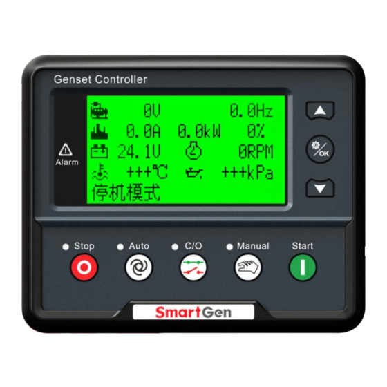
HGM8140 MILITARY GENSET CONTROLLER USER MANUAL 4.2 CONTROLLER PANEL HGM8140D Front Panel NOTE: Part of indicator lights illustration: Alarm Indicators: slowly flash when warn alarms; fast flash when shutdown alarms; light is off when no alarms. 4.3 LCD DISPLAY There are three display interfaces: default interface; OEM plant interface and terminal users interface. -
Page 11: Auto Start/Stop Operation
, its indicator lights, and controller enters Auto mode. Starting Sequence, HGM8140: Generator enters into ―start delay‖ as soon as ―Remote Start‖ input is active or DC input volt is below pre-set start volt. Start Delay timer is shown on LCD. -
Page 12: Manual Start/Stop Operation
Enter ―generator at rest‖ as soon as ―after stop time‖ is over. If genset fail to stop, controller will initiate alarms (fail to stop warning shown on LCD). 4.5 MANUAL START/STOP OPERATION HGM8140: Manual mode is selected by pressing the button; a LED besides the button will illuminate to confirm the operation; press button to start the genset, it can automatically judge crank success and accelerate to high speed running. -
Page 13: Protection
HGM8140 MILITARY GENSET CONTROLLER USER MANUAL 5 PROTECTION 5.1 WARNINGS When controllers detects the warning signals, alarm only and not stop the genset, besides, the LCD displays the warning information Table 4 – Controller Warning Alarms Type Description When the controller detects that the engine speed is 0 and the delay is... - Page 14 HGM8140 MILITARY GENSET CONTROLLER USER MANUAL Type Description When it is enabled and the controller detects that config. sensor temperature (sensor type: temperature sensor) has exceeded the High Temperature pre-set value, it will initiate a warning alarm and the corresponding alarm information will be displayed on LCD.
-
Page 15: Trip Alarm
HGM8140 MILITARY GENSET CONTROLLER USER MANUAL Type Description displayed on LCD. When it is enabled and low oil pressure shutdown is prohibited or low Low Oil Pressure oil pressure of input port shutdown is prohibited, controller will initiate a warning alarm and the corresponding alarm information will be warning Input displayed on LCD. -
Page 16: Shutdown Alarms
HGM8140 MILITARY GENSET CONTROLLER USER MANUAL Type Description alarm can be reset by changing maintenance parameters. If reverse power detection is enabled, when the controller detects that the reverse power value (power is negative) has fallen below the Reverse Power pre-set value and the action select ―Trip and Stop‖, it will initiate a trip... - Page 17 HGM8140 MILITARY GENSET CONTROLLER USER MANUAL Type Description When controller detects the current value is higher than the set value Gen Over Current and the delay value is not 0, it will send stop signals and the corresponding alarm information will be displayed on LCD.
- Page 18 HGM8140 MILITARY GENSET CONTROLLER USER MANUAL Type Description After engine start, controller dose not receive data signals, via J1939, ECU Comm. Fail controller send stop signals. When the controller detects that the sensor is open circuit and the Flexible Sensor 1 action select ―Shutdown Alarm‖, it will initiate a shutdown alarm and the...
-
Page 19: Wirings Connection
HGM8140 MILITARY GENSET CONTROLLER USER MANUAL 6 WIRINGS CONNECTION 6.1 HGM8140M MILITARY GENSET CONTROLLER PANNEL Fig.2 – HGM8140M Controller Rear Panel Table 8 - Terminal Wiring Connection Description Function Cable Size Remarks 2.5mm Connected with negative of starter battery Connected with positive of starter battery. If wire 2.5mm... - Page 20 HGM8140 MILITARY GENSET CONTROLLER USER MANUAL Function Cable Size Remarks Grounding is Aux. Input 2 1.0mm active(B-) Grounding is Aux. Input 3 1.0mm active (B-) Grounding is Aux. Input 4 1.0mm active (B-) Grounding is Aux. Input 5 1.0mm active (B-) Grounding is Aux.
- Page 21 HGM8140 MILITARY GENSET CONTROLLER USER MANUAL Function Cable Size Remarks Connected to U-phase output Genset U-phase voltage 1.0mm of genset (2A fuse monitoring input recommended). Connected to V-phase output Genset V-phase voltage 1.0mm of genset (2A fuse monitoring input recommended).
-
Page 22: Hgm8140D Mlitary Genset Controller Back Panel
HGM8140 MILITARY GENSET CONTROLLER USER MANUAL 6.2 HGM8140D MLITARY GENSET CONTROLLER BACK PANEL Table 9 - Terminal Wiring Connection Description Function Cable Size Remarks 2.5mm Connected with negative of starter battery Connected with positive of starter battery. If wire 2.5mm length is over 30m, better to double wires in parallel. -
Page 23: Scops And Definitions Of Programmable Parameters
HGM8140 MILITARY GENSET CONTROLLER USER MANUAL 7 SCOPS AND DEFINITIONS OF PROGRAMMABLE PARAMETERS 7.1 CONTENTS AND SCOPES OF PARAMETERS Table 10 - Parameters Settings and Scope Items Parameters Defaults Description Time from mains abnormal or remote start Start Delay (0~3600)s signal is active to start genset. - Page 24 HGM8140 MILITARY GENSET CONTROLLER USER MANUAL Items Parameters Defaults Description controller does not detect over voltage signal. When generator voltage has fallen below the set value and the ―Gen abnormal delay‖ Under Volt has expired, Gen Under Voltage Shutdown (30-620)V Shutdown is active.
- Page 25 HGM8140 MILITARY GENSET CONTROLLER USER MANUAL Items Parameters Defaults Description Voltage value and remains for 20s, It will initiate a warning alarm signal. Only warning and not to shutdown the generator. When battery voltage has fallen below the Battery Under...
- Page 26 HGM8140 MILITARY GENSET CONTROLLER USER MANUAL Items Parameters Defaults Description details to see Table 12. Digital Input (0-20.0)s Delay Factory default: Low Coolant Level Warn, Digital Input 5 (0-26) details to see Table 12. Digital Input (0-20.0)s Delay Factory default: User-defined, details to see...
- Page 27 HGM8140 MILITARY GENSET CONTROLLER USER MANUAL Items Parameters Defaults Description Pressure Sensor (0-12) SGX , details to see Table 13. Curve Fuel Level Sensor (0-7) SGD, details to see Table 13. Curve Number of generator poles, which can be Poles...
- Page 28 HGM8140 MILITARY GENSET CONTROLLER USER MANUAL Items Parameters Defaults Description 0: Default Theme; 1: OEM plant Theme; Custom Theme (0-2) 2: terminal Users Theme; Note1: if ―high temperature inhibit‖ is configured, or set auxiliary input as ―inhibit high temperature stop‖ and this input is active, when temperature is higher than the preset value, or high temperature alarm input is active, controller will send warning signal only and not stop the unit.
- Page 29 HGM8140 MILITARY GENSET CONTROLLER USER MANUAL Item Description Close when the generator enters into Warming Up delay while High Speed Control open after cooling delay. Auto Mode The controller is in automatic mode. Output when shutdown alarms appeared. Trip and Stop When warning and shutdown alarms appear, audible alarm output is fixed as 300s.
- Page 30 HGM8140 MILITARY GENSET CONTROLLER USER MANUAL Item Description Custom Combined 3 Custom Combined 4 Custom Combined 5 Custom Combined 6 Reserved Reserved Reserved Reserved Reserved Reserved Reserved It is controlled by cooler of temperature sensor‘s limited threshold. Cooler Control Action when common trip and stop alarm.
- Page 31 HGM8140 MILITARY GENSET CONTROLLER USER MANUAL Item Description Under Volt. Shutdown Action when generator low voltage shutdown. Reserved Action when controller detects generator have over power. Over Power Alarm Reserved Gen Reverse Power Action when controller detects generator have reverse power.
-
Page 32: User-Defined Period Output
HGM8140 MILITARY GENSET CONTROLLER USER MANUAL Item Description Reserved Aux Input 1 Active Action when input port 1 is active Aux Input 2 Active Action when input port 2 is active Aux Input 3 Active Action when input port 3 is active... -
Page 33: User-Defined Combination Output
HGM8140 MILITARY GENSET CONTROLLER USER MANUAL 7.3 USER-DEFINED COMBINATION OUTPUT Defined combination output is composed by 3 parts, OR condition output SW1, OR condition output SW2, AND condition output SW3. SW1 or SW2 is TRUE, while SW3 is TRUE, Defined combination output is active;... - Page 34 HGM8140 MILITARY GENSET CONTROLLER USER MANUAL Table 12 - Defined Contents of Digit Input Port1~5 (All active when connect to grand (B~)) Type Description Including following functions, Indication: indicate only, not warning or shutdown. Warning: warn only, not shutdown. Shutdown: alarm and shutdown immediately...
- Page 35 When input is active, all keys except for on the Remote Control Mode panel of HGM8140 are inactive and remote control mode will display on the LCD. Charge Failure Connected to charge alt failure output port.
- Page 36 HGM8140 MILITARY GENSET CONTROLLER USER MANUAL Item Content Remark 11 Digital Low Input Active 12 Digital High Input Active 0 Not used 1 Custom Resistor Curve 2 VDO 10Bar 3 SGH 4 SGD 5 CURTIS Defined resistance‘s range is Pressure Sensor 6 DATCON 10Bar 0Ω-6000Ω, default is SGX sensor.
-
Page 37: Parameters Setting
HGM8140 MILITARY GENSET CONTROLLER USER MANUAL speed signal” maybe caused. If genset without oil pressure sensor, please don’t select corresponding items. If not select generator frequency in crank disconnect setting, controller will not collect and display the relative power quantity (can be used in water pump set); if not select speed in crank disconnect setting, the engine speed displayed in controller is calculated by generator signal. -
Page 38: Sensor Setting
HGM8140 MILITARY GENSET CONTROLLER USER MANUAL Press simultaneously to adjust LCD contrast ratio and make LCD character display more clearly. Contrast ratio adjustment range: 0-7. 9 SENSOR SETTING 1) When reselect sensors, the sensor curve will be transferred into the standard value. For example, if temperature sensor is SGH (120°... -
Page 39: Commissioning
ATS transfers to genset on load. If not, please check ATS controlling wiring connection according to this user manual; If there is any other question, please contact SmartGen‘s service. HGM8140 Military Genset Controller Version 1.0... -
Page 40: Typical Application
HGM8140 MILITARY GENSET CONTROLLER USER MANUAL 11 TYPICAL APPLICATION Fig.3 - HGM8140M Typical Application Fig.4 - HGM8140 Connection Schematic diagram HGM8140 Military Genset Controller Version 1.0 2016-12-07 Page 39 of 54... - Page 41 HGM8140 MILITARY GENSET CONTROLLER USER MANUAL Fig.5 – Single Phase 2-Wire Wiring Connection Fig.6 – 2-Phase 3-Wire Connection Note: Expand relay with high capacity in start and fuel output is recommend. HGM8140 Military Genset Controller Version 1.0 2016-12-07 Page 40 of 54...
-
Page 42: Installation
Fig.7 - HGM8140D Overall and Cutout Dimensions Fig.8 - HGM8140M Overall and Installation Dimensions HGM8140 military genset controller can suit for widely range of battery voltage (8~35) VDC. Negative of battery must be connected with the engine shell. Diameter of wire that connects from HGM8140 Military Genset Controller Version 1.0... - Page 43 HGM8140 MILITARY GENSET CONTROLLER USER MANUAL power supply to battery must be over 2.5mm . If floating charge configured, please firstly connect output wires of charger to battery‘s positive and negative directly, then, connect wires from battery‘s positive and negative to controller‘s positive and negative input ports in order to prevent charge disturbing the controller‘s normal working.
-
Page 44: Connections Of Controller With J1939 Engine
HGM8140 MILITARY GENSET CONTROLLER USER MANUAL 13 CONNECTIONS OF CONTROLLER WITH J1939 ENGINE 13.1 CUMMINS ISB/ISBE Table 16 - Connector B Terminals of controller Connector B Remark Programmable relay output1 set as ―Fuel Output‖ Relay Output1 Start relay output Connect with starter coil directly. -
Page 45: Cummins Qsm11(Import)
HGM8140 MILITARY GENSET CONTROLLER USER MANUAL 13.3 CUMMINS QSM11(import) Suitable for CM570 engine control module, engine type: QSM11 G1, QSM11 G2. Table 20 -C1 Connector Terminals of controller C1 connector Remark Programmable relay output 1 set as ―Fuel Output‖ Relay Output 1 5&8... -
Page 46: Cummins Gcs-Modbus
HGM8140 MILITARY GENSET CONTROLLER USER MANUAL 13.5 CUMMINS GCS-MODBUS It is suitable for GCS engine control module. RS485-MODBUS used to read information of engine. Engine types are QSX15, QST30, QSK23 / 45/60/78 and so on. Table 24 -D-SUB Connector 06... -
Page 47: Detroit Diesel Ddec Iii / Iv
HGM8140 MILITARY GENSET CONTROLLER USER MANUAL Terminals of controller OEM connector of engine Remark Using impedance 120Ω connecting line. CAN(H) Using impedance 120Ω connecting line. CAN(L) Engine type: Common J1939 13.8 DETROIT DIESEL DDEC III / IV Table 28 - Engine CAN Connector... -
Page 48: Mtu Mdec
HGM8140 MILITARY GENSET CONTROLLER USER MANUAL 13.11 MTU MDEC Suitable for MTU engines, 2000 series, 4000series Table 31 - X1 Connector Terminals of controller X1 connector Remark Configure relay output 1 as ―Fuel Output‖ Relay Output 1 Start relay output... -
Page 49: Perkins
HGM8140 MILITARY GENSET CONTROLLER USER MANUAL Using impedance 120Ω connecting line. CAN(L) X23 1 Engine type: Common J1939 13.14 PERKINS It is suitable for ADEM3/ ADEM4 engine control module. Engine type is 2306, 2506, 1106, and 2806. Table 36 - Connector... -
Page 50: Volvo Edc4
HGM8140 MILITARY GENSET CONTROLLER USER MANUAL 13.17 VOLVO EDC4 Suitable engine types: TD520, TAD520 (optional), TD720, TAD720 (optional), TAD721, TAD722, and TAD732. Table 40 - Connector Terminals of controller Connector Remark Expanded 30A relay, and relay offers battery Configure relay output 1 as ―Fuel Output‖. -
Page 51: Yuchai
HGM8140 MILITARY GENSET CONTROLLER USER MANUAL 13.19 YUCHAI It is suitable for BOSCH common rail pump engine. Table 42 - Engine 42 Pin Connector Terminals of controller Engine 42 pins port Remark Configure relay output 1 as ―Fuel Output‖. Relay Output 1 1.40... -
Page 52: Ethernetinterface
The communication between the controller and monitoring equipment is carried out using TCP ModBus protocol. NOTE: In this connection mode controller parameters can be set. SmartGen provides testing software for this connection mode. Communication protocol can be obtained from the SmartGen service. -
Page 53: Troubleshooting
HGM8140 MILITARY GENSET CONTROLLER USER MANUAL For this connection crossover cable must be used. Crossover cable: EIA/TIA 568A standard on one end and EIA/TIA 568B on the other end. NOTE: If PC network port has Auto MDI/MDIX function, parallel cable can also be used. - Page 54 HGM8140 MILITARY GENSET CONTROLLER USER MANUAL _________________________________ HGM8140 Military Genset Controller Version 1.0 2016-12-07 Page 53 of 54...
Need help?
Do you have a question about the HGM8140 and is the answer not in the manual?
Questions and answers