
Subscribe to Our Youtube Channel
Related Manuals for Smartgen HGM6100N Series


Summary of Contents for Smartgen HGM6100N Series
- Page 1 HGM6100N SERIES (HGM6110N/6120N/6110NC/6120NC/6110CAN/6120CAN) GENSET CONTROLLER USER MANUAL SMARTGEN (ZHENGZHOU) TECHNOLOGY CO., LTD.
- Page 2 SmartGen Technology at the address above. Any reference to trademarked product names used within this publication is owned by their respective companies. SmartGen Technology reserves the right to change the contents of this document without prior notice. Table 1 – Software Version Date...
- Page 3 “7.5 CONDITIONS OF CRANK 2020-08-18 DISCONNECT (Table 5)”. Modified the terminal number of output port 2 of typical 2020-09-10 application diagrams. Deleted MTU MDEC wiring diagram; 2021-06-22 Added partial parameters. HGM6100N Series Genset Controller User Manual Page 3 of 47...
-
Page 4: Table Of Contents
13 CONNECTIONS OF CONTROLLER WITH J1939 ENGINE ..............39 13.1 CUMMINS ISB/ISBE ........................39 13.2 CUMMINS QSL9 ..........................39 13.3 CUMMINS QSM11 (IMPORT) ......................40 13.4 CUMMINS QSX15-CM570 ......................40 HGM6100N Series Genset Controller User Manual Page 4 of 47... - Page 5 13.14 SCANIA ............................44 13.15 VOLVO EDC3 ..........................44 13.16 VOLVO EDC4 ..........................45 13.17 VOLVO-EMS2 ..........................45 13.18 YUCHAI ............................46 13.19 WEICHAI ............................46 14 FAULT FINDING ............................47 HGM6100N Series Genset Controller User Manual Page 5 of 47...
-
Page 6: Overview
OVERVIEW HGM6100N series automatic controller, integrating digital, intelligent and network techniques, is used for automatic control and monitoring system of single genset. It can carry out functions of automatic start/stop, data measurement, alarm protection and “three remote” (remote control, remote measurement and remote communication). - Page 7 Add rubber gasket between shell and controller screen, the waterproof can reach IP65; Controller is fixed by metal fixing clips; Modular design, flame-retardant ABS shell, pluggable terminal, embedded mounting, compact structure and easy installation. HGM6100N Series Genset Controller User Manual Page 7 of 47...
-
Page 8: Specification
IP65: when water-proof gasket installed between control panel and Protection Level enclosure. Apply AC2.2kV voltage between high voltage terminal and low Insulation Intensity voltage terminal. The leakage current is not more than 3mA within 1min. Weight 0.56kg HGM6100N Series Genset Controller User Manual Page 8 of 47... -
Page 9: Operation
Up cursor and increase value in setting menu. Screen scroll; Down/Decrease Down cursor and decrease value in setting menu. Return to homepage when in main interface; Home/Return Exit when in parameters setting interface. HGM6100N Series Genset Controller User Manual Page 9 of 47... -
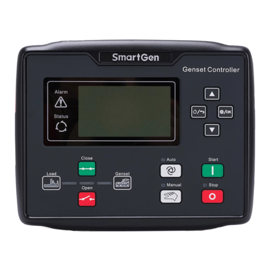
Page 10: Controller Panel
Status Indicator: won’t illuminate when genset stand by; blink 1 time per second in start or stop process and always illuminate when runs normally; for HGM6100CAN, press start key in auto mode or manual mode, ECU power outputs and status indicator always illuminates. HGM6100N Series Genset Controller User Manual Page 10 of 47... -
Page 11: Automatic Start/Stop Operation
MANUAL START/STOP OPERATION HGM6120: Manual Mode is active when press and its indicator illuminates. Under this mode, press to start genset, it can automatically detect crank disconnect and accelerate to high HGM6100N Series Genset Controller User Manual Page 11 of 47... -
Page 12: Emergency Start
Low Fuel Level warning is active, controller will send warning alarm signal and it will be displayed in LCD. During genset normal running process, when the voltage difference Failed to Charge HGM6100N Series Genset Controller User Manual Page 12 of 47... - Page 13 (power is positive) has exceeded the pre-set value and the action selects “Warn”, it will initiate a warning alarm. If an error message is received from ECU via J1939, it will initiate a 17 ECU Warn warning alarm. HGM6100N Series Genset Controller User Manual Page 13 of 47...
-
Page 14: Shutdown Alarms
LCD. Maintenance type is running time. When genset running time is longer 18 Maintenance Due than maintenance time of user setting, or the maintenance type is date, HGM6100N Series Genset Controller User Manual Page 14 of 47... - Page 15 LCD. NOTE: ECU warning and Shutdown alarm explanation: check engine according to detailed alarm contents; otherwise check engine user manual according to SPN alarm code for gaining information. HGM6100N Series Genset Controller User Manual Page 15 of 47...
-
Page 16: Connections
CONNECTIONS Compared with HGM6120, HGM6110 doesn’t have 3-phase input terminal of mains voltage. The back panel of HGM6120 is as below. Fig.3 – Controller Rear Panel Drawing HGM6100N Series Genset Controller User Manual Page 16 of 47... - Page 17 Connect to V phase output (2A fuse is recommended). sensing Input Gens W phase Voltage 1.0mm Connect to W phase output (2A fuse is recommended). Sensing Input Gens N2 Input 1.0mm Connect to generator N-wire. HGM6100N Series Genset Controller User Manual Page 17 of 47...
- Page 18 (the controller without CANBUS function doesn’t have this terminal). CAN H 0.5mm NULL NOTE: USB ports in controller rear panel are programmable parameter ports; user can directly program via PC. HGM6100N Series Genset Controller User Manual Page 18 of 47...
-
Page 19: Parameter Range And Definition
(3-3600)s Time for cooling before stopping. 16(11) Stop Idle Time (0-3600)s Idle running time when genset stop. Stop electromagnet’s power-on time when 17(12) ETS Solenoid Hold (0-120)s genset is stopping. HGM6100N Series Genset Controller User Manual Page 19 of 47... - Page 20 When fuel level sensor value is under this Fuel Level 30(25) (0-100)% point and remains for 10s, genset sends out Warning Value warning alarm, only warn but not shutdown. HGM6100N Series Genset Controller User Manual Page 20 of 47...
- Page 21 Active Type (0-1) Factory default: close. 47(42) Delay (0-20.0)s Factory default: Low oil pressure alarm. See 48(43) Aux. Input 2 (0-25) table 9. 49(44) Active Type (0-1) Factory default: close. HGM6100N Series Genset Controller User Manual Page 21 of 47...
- Page 22 SGX. See table 10. Curve Type Fuel Level Sensor 72(67) (0-7) SGD. See table 10. Curve Type Number magnetic poles, used 73(68) Generator Poles (2-64) calculating rotating speed of generator without speed sensor. HGM6100N Series Genset Controller User Manual Page 22 of 47...
- Page 23 88(83) 1: OEM Plant Theme; 2: Custom Theme (0-2) Terminal Users Theme 89(84) It is the time of the genset fuel output during Fuel Output Time (1-60)s 85(80) power on. HGM6100N Series Genset Controller User Manual Page 23 of 47...
- Page 24 NOTE4: If default password (0318) isn’t changed, it doesn’t need to input when configuring parameters via PC software; if the password is changed for the first time via PC software, it need to input password in password window. HGM6100N Series Genset Controller User Manual Page 24 of 47...
-
Page 25: Defined Contents Of Programmable Output 1-4
Genset output in start output status and open in other status. ECU Stop Used for ECU engine and control its stop. ECU Power Used for ECU engine and control its power. HGM6100N Series Genset Controller User Manual Page 25 of 47... - Page 26 If oil pressure is above 100kPa or output delay is more than 1minute, it will stop output; if unit is in re-heating state, oil pump control will always output. HGM6100N Series Genset Controller User Manual Page 26 of 47...
-
Page 27: Defined Contents Of Programmable Input 1-5
In this mode, under voltage, under frequency and under speed Idle Control Mode are not protected. 60Hz Select It is used for J1939 engine with CANBUS port, when input is HGM6100N Series Genset Controller User Manual Page 27 of 47... - Page 28 5RPM. When input active, Over Current Fault Shutdown controller will initiate shutdown alarms. Only HGM6100N has these When input active, functions. Over Speed Shutdown controller will initiate shutdown alarms. HGM6100N Series Genset Controller User Manual Page 28 of 47...
-
Page 29: Sensor Selection
4 User Configured (4-20mA) sensor. 5 User Configured (0-5V) 6 Digital Closed 7 Digital Open NOTE: It needs special instructions for ordering when the genset uses 4-20mA or 0-5V sensors. HGM6100N Series Genset Controller User Manual Page 29 of 47... -
Page 30: Conditions Of Crank Disconnect Selection
HGM6110, there are no items 1-5 in table 7; programmable output 1-4 have no digital outputs about mains. Please modify the parameters in standby mode (crank conditions, auxiliary input and output HGM6100N Series Genset Controller User Manual Page 30 of 47... - Page 31 User may select display language as Chinese, English, Spanish, Russian, Portuguese, Turkey, Polish and French. LCD contrast ratio adjustment Press ) and adjust LCD contrast ratio, which shall make the LCD characters clearer. Adjustment range is 0-9. HGM6100N Series Genset Controller User Manual Page 31 of 47...
-
Page 32: Sensor Setting
Table 12 – Conventional Pressure Unit Conversion Table 1N/m (pa) 1kgf/cm 1bar (1b/in ) psi - - - 1.02x10 1x10 1.45x10 1kgf/cm 9.8x10 0.98 14.2 1bar 1x10 1.02 14.5 - - 1psi 6.89x10 7.03x10 6.89x10 HGM6100N Series Genset Controller User Manual Page 32 of 47... -
Page 33: Commissioning
ATS and make genset take load. If it not likes this, please check connections of ATS according to this manual. — If there are any other questions, please contact SmartGen’s service. HGM6100N Series Genset Controller User Manual... -
Page 34: Typical Application
11 TYPICAL APPLICATION Fig.5 – HGM6110NC Typical Application Diagram Fig.6 – HGM6120NC Typical Application Diagram HGM6100N Series Genset Controller User Manual Page 34 of 47... - Page 35 Fig.7 – HGM6110CAN Typical Application Diagram Fig.8 – HGM6120CAN Typical Application Diagram HGM6100N Series Genset Controller User Manual Page 35 of 47...
- Page 36 Fig. 9 – Single Phase 2 Wire Fig. 10 – 2 Phase 3 Wire NOTE: Recommend that the output of crank and Fuel expand high capacity relay. HGM6100N Series Genset Controller User Manual Page 36 of 47...
-
Page 37: Installation
(when expansion relay coil links DC), or add RC loop (when expansion relay coil links AC), in case controller or other equipments are interfered. AC Input HGM6110N series controller must externally connect to current transformer; CT secondary HGM6100N Series Genset Controller User Manual Page 37 of 47... - Page 38 B. When there is load current, open circuit is inhibited in the CT secondary side. 5) Withstand Voltage Test When the controller has been installed in the control panel, during the test please disconnect all the terminals, in case high voltage damages the controller. HGM6100N Series Genset Controller User Manual Page 38 of 47...
-
Page 39: Connections Of Controller With J1939 Engine
CAN_SCR SAE J1939 shield-E (connect to ECU terminal only). CAN(H) SAE J1939 signal-C Using impedance 120Ω connecting line. CAN(L) SAE J1939 return-D Using impedance 120Ω connecting line. Engine type: Cummins-CM850. HGM6100N Series Genset Controller User Manual Page 39 of 47... -
Page 40: Cummins Qsm11 (Import)
Engine type: Cummins QSX15-CM570. 13.5 CUMMINS GCS-MODBUS It is suitable for GCS engine control module. Use RS485-MODBUS to read information of engine. Engine types are QSX15, QST30, QSK23 / 45/60/78 and so on. HGM6100N Series Genset Controller User Manual Page 40 of 47... -
Page 41: Cummins Qsm11
Setting to pulse raise speed control, normally open output. Making 19 connect Configurable output 3 19&41 with 41 for 0.1s during high-speed warming controller external HGM6100N Series Genset Controller User Manual Page 41 of 47... -
Page 42: Detroit Diesel Ddec Iii/Iv
Set configurable output 1 as “Fuel Relay Configurable output 1 G, J Output”. Starting relay output CAN communication shielding line. CAN GND Using impedance 120Ω connecting line. CAN(H) Using impedance 120Ω connecting line. CAN(L) HGM6100N Series Genset Controller User Manual Page 42 of 47... -
Page 43: Mtu Adec (Smart Module)
SAM (X23 port) Remark CAN_SCR X23 3 CAN communication shielding line. CAN(H) X23 2 Using impedance 120Ω connecting line. CAN(L) X23 1 Using impedance 120Ω connecting line. Engine type: Common J1939. HGM6100N Series Genset Controller User Manual Page 43 of 47... -
Page 44: Perkins
Table 35 – “Data bus” Connector Terminals of controller “Data bus” connector Remark CAN_SCR CAN communication shielding line. CAN(H) Using impedance 120Ω connecting line. CAN(L) Using impedance 120Ω connecting line. HGM6100N Series Genset Controller User Manual Page 44 of 47... -
Page 45: Volvo Edc4
Using impedance 120Ω connecting line. CAN(L) 2(Lo) Using impedance 120Ω connecting line. Engine type: Volvo-EMS2. NOTE: When this engine type is selected, preheating time should be set to at least 3 seconds. HGM6100N Series Genset Controller User Manual Page 45 of 47... -
Page 46: Yuchai
CAN(L) 1.34 Using impedance 120Ω connecting line. Engine type: GTSC1. NOTE: If there is any question of connection between controller and ECU communication, please feel free to contact Smartgen service. HGM6100N Series Genset Controller User Manual Page 46 of 47... -
Page 47: Fault Finding
RS485 Communication Failure Check if A and B of RS485 is connected reversely; Check if PC COM port is damaged; 120Ω resistance between RS485’s A and B is recommended. _________________________________ HGM6100N Series Genset Controller User Manual Page 47 of 47...
Need help?
Do you have a question about the HGM6100N Series and is the answer not in the manual?
Questions and answers
What is the maintenance password