ITech IT6000C Series User Manual
Bi-directional programmable dc power supply
Hide thumbs
Also See for IT6000C Series:
- User manual (177 pages) ,
- User manual (211 pages) ,
- User manual (251 pages)
Table of Contents
Advertisement
Quick Links
Download this manual
See also:
User Manual
Advertisement
Table of Contents

Subscribe to Our Youtube Channel
Related Manuals for ITech IT6000C Series


Summary of Contents for ITech IT6000C Series
- Page 1 ООО "Техэнком" Контрольно-измерительные приборы и оборудование www.tehencom.com Bi-directional Programmable DC Power Supply IT6000C Series User Manual Model: IT6000C Series Version: V1.0/01,2019...
- Page 2 CAUTION sign until the in- pose. ITECH shall not be held liable Manual Part Number dicated conditions are for errors or for incidental or indirect fully understood and met.
-
Page 3: Warranty
Warranty ITECH warrants that the product will be free from defects in material and work- manship under normal use for a period of one (1) year from the date of delivery (except those described in the Limitation of Warranty below). -
Page 4: Safety Symbols
Failure to comply with these precautions or specific warn- ings elsewhere in this manual will constitute a default under safety standards of design, manufacture and intended use of the instrument. ITECH assumes no li- ability for the customer’s failure to comply with these precautions. - Page 5 This instrument is used for industrial purposes, do not apply this product to IT power supply system. • Never use the instrument with a life-support system or any other equip- ment subject to safety requirements. Copyright © Itech Electronic Co., Ltd.
-
Page 6: Environmental Conditions
The instrument is designed for indoor use and an area with low condensation. The table below shows the general environmental requirements for the instrument. Environmental Conditions Requirements Operating temperature 0°C~40°C Operating humidity 20%~80%( non-condensation) Storage temperature -10°C~70 °C Copyright © Itech Electronic Co., Ltd. -
Page 7: Regulation Tag
The service life of the product is 10 years. The product can be used safely within the environmental protection period; otherwise, the product should be put into the recycling system. Copyright © Itech Electronic Co., Ltd. -
Page 8: Waste Electrical And Electronic Equipment (Weee) Directive
According to the equipment classifi- cation in Annex I of the WEEE direc- tive, this instrument belongs to the “Monitoring” product. If you want to return the unnecessary instrument, please contact the near- est sales office of ITECH. Copyright © Itech Electronic Co., Ltd. -
Page 9: Compliance Information
2. Connection of the instrument to a test object may produce radiations beyond the specified limit. 3. Use high-performance shielded interface cable to ensure conformity with the EMC standards listed above. Safety Standard IEC 61010-1:2010/ EN 61010-1:2010 Copyright © Itech Electronic Co., Ltd. -
Page 10: Table Of Contents
4.4.3 Set the Output-On/Output-Off Delay ............70 4.5 Protection Function for Power Supply ..............70 4.5.1 Set Over-Voltage Protection (OVP)............. 73 4.5.2 Set Over-Current Protection (OCP)............. 74 4.5.3 Set Over-Power Protection (OPP)............... 75 4.5.4 Set Under-Current Protection (UCP)............76 Copyright © Itech Electronic Co., Ltd. VIII... - Page 11 6.1.7 IT6018C-800-60 ..................138 6.1.8 IT6036C-800-120 ..................140 6.1.9 IT6018C-2250-20 ..................142 6.2 Supplemental Characteristics................145 A Appendix ........................146 A.1 Specifications of Red and Black Test Lines............146 A.2 Fuse Replacement ....................147 Copyright © Itech Electronic Co., Ltd.
-
Page 12: Inspection And Installation
For details, see Connecting the Power Cord. USB communication This accessory is se- cable lected when the USB in- terface is used for starting up remote operation. Copyright © Itech Electronic Co., Ltd. -
Page 13: Instrument Size Introduction
The instrument should be installed at well-ventilated and rational-sized space. Please select appropriate space for installation based on the instrument size. The detailed dimension drawings of the IT6000C series are as follows: 3U Models Copyright © Itech Electronic Co., Ltd. -
Page 14: Connecting The Power Cord
L1, L2 and L3 terminals of power input on the rear panel of the in- strument; the yellow-green wire is grounding wire, which is connected to the PE terminal of power input on the rear panel. Copyright © Itech Electronic Co., Ltd. - Page 15 (PE). 5. Mount the protective cover back to its original position. 6. Connect the other end of the power cable to the required AC distribution box. The schematic is shown below. Copyright © Itech Electronic Co., Ltd.
-
Page 16: Connecting The Device Under Test (Dut)
1.4 Connecting the Device Under Test (DUT) This section describes how to connect the test cables between the instrument and DUT. Precautions To prevent electric shock and damage to the instrument, observe the following precautions. Copyright © Itech Electronic Co., Ltd. - Page 17 • Always use test cables provided by ITECH to connect the equipment. If test cables from other factories are used, please confirm the maximum current that the test cables can withstand.
- Page 18 The connection diagram and steps of remote measurement are as follows: Copyright © Itech Electronic Co., Ltd.
- Page 19 Lethal voltages may remain at the out- put terminals after turn-off. Verify that there is no dangerous voltage on the output or sense terminals before touching them. Copyright © Itech Electronic Co., Ltd.
-
Page 20: Quick Start
More functions, technical indicators and technical innovations are described below: • The standard 3U chassis of the IT6000C series instruments can accommo- date up to 3 modules. • Internal modules can be run in series or in parallel for voltage sharing or cur- rent sharing. - Page 21 • When the Sense function is turned on, it can ensure that the DUT is safe in case of reverse connection or open circuit of the Sense line. Copyright © Itech Electronic Co., Ltd.
-
Page 22: Front-Panel Overview
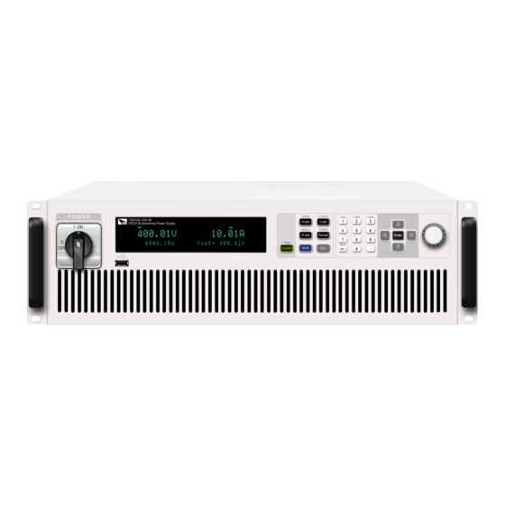
18,000W. 2.2 Front-Panel Overview For the IT6000C series Bi-directional Programmable DC Power Supply, all front panels of the 3U model are the same, and the operation panels of other models are the same as those of the 3U model. The following is the front panel sche- matic of the 3U model. -
Page 23: Keyboard Introduction
3 Function and composite keys 7 Vent hole 4 Numeric and composite keys 8 USB storage device connection port 2.2.1 Keyboard Introduction The keyboard introduction of IT6000C series Bi-directional Programmable DC Power Supply is shown as follows. Table 2–1 Keys Description Keys Description [Esc] Press this key to exit the current operation interface. - Page 24 Generate a local trigger signal. [0]-[9] Numeric keys [Shift]+[1] (Log) Enter the data logging function menu. [Shift]+[2] (Lock) Turn the keyboard lock on or off. [Shift]+[3] (Local) Switch remote control mode to local control mode. Copyright © Itech Electronic Co., Ltd.
-
Page 25: Push-On Knob
[Enter] Operation confirmation key 2.2.2 Push-on Knob The IT6000C series Bi-directional Programmable DC Power Supply provides a knob on the front panel as shown in the next figure. The functions of the posh-on knob is described as follows. •... -
Page 26: Vfd Indicator Lamps Description
After completing the value setting or selecting a menu item, pushing the knob acts like pressing [Enter] key to confirm the operation. 2.2.3 VFD Indicator Lamps Description The IT6000C series Bi-directional Programmable DC Power Supply VFD indica- tor lamps description is as follows: Table 2–2 VFD Indicator Lamps Description... -
Page 27: Rear Panel Introduction
Контрольно-измерительные приборы и оборудование www.tehencom.com Quick Start 2.3 Rear Panel Introduction The rear panel of the 3U model of the IT6000C series Bi-directional Program- mable DC Power Supply (after removing the protective cover) is shown below. 3U Models 1. Sense terminals (Vs+, Vs-) 2. -
Page 28: Power-On Self-Test
Power Switch Introduction User can adjust the power switch directly to turn on or turn off the instrument. The status of Power switch is as follows. Copyright © Itech Electronic Co., Ltd. - Page 29 Calibration Data Lost The factory calibration data in EE- PROM is lost. Config Data Lost The latest operation state of the in- strument is lost. NETWORKING… The parallel operations are abnormal and cannot finish the networking. Copyright © Itech Electronic Co., Ltd.
- Page 30 3. Check whether the power voltage matches with the supply voltage. Please refer to 1.3 Connecting the Power Cord to select proper AC input. 4. If you need additional assistance, contact ITECH technical support engineer. Copyright © Itech Electronic Co., Ltd.
-
Page 31: Basic Operation
PC to control the power supply remotely. – During remote control operation, the remote symbol “Rmt” is displayed. All panel keys, except the [On/Off] and [Shift]+[3] (Local) keys, are locked. Copyright © Itech Electronic Co., Ltd. -
Page 32: Key Lock Function
Voltage/Current rise time: V-Rise Time/I-Rise Time Voltage/Current fall time: V-Fall Time/I-Fall Time On/Off switch delay: On Delay/Off Delay Internal resistance of the power supply: Output Res Protect menu OCP/OVP/OPP/UCP/UVP switch status: On/Off OCP/OVP/OPP/UCP/UVP limit setting: Level Copyright © Itech Electronic Co., Ltd. -
Page 33: Save Operation
3. Press [Enter] to recall the parameters. 3.5 Data Logging Function The IT6000C series Bi-directional Programmable DC Power Supply supports the recording and saving of test data. This Chapter introduces how to use this function in details. - Page 34 0 - 3600 Source This parameter indicates the source Use the Left and of recorded data, including voltage Right arrow key or (V), current (I), voltage and current the rotation knob to (V/I). select. Copyright © Itech Electronic Co., Ltd.
- Page 35 This setting result is only valid for data recording function. When List function is used, the method for triggering the running of List files needs to be addi- tionally set (by default, triggered by the panel). Copyright © Itech Electronic Co., Ltd.
-
Page 36: System Menu Function
3.6 System Menu Function This Chapter offers a general introduction of system menus, allowing users to have a preliminary understanding of system functions of this IT6000C series. The steps of the system menu function are as follows: 1. Press the composite keys [Shift]+[P-set] (System) on the front panel to en- ter the system menu. - Page 37 DataLogger Trig Set the trigger method for the data logging. Source Manual trigger Manual Bus trigger External trigger External Set the communication information between instrument and I/O Con USB communication interface LAN communication interface Copyright © Itech Electronic Co., Ltd.
- Page 38 If it is not involved, there is no need to set it. • Socket Port: 30000 Set the port number. Serv- Configure the LAN services. Conf MDNS: MDNS service state. • • PING: PING service state. • Copyright © Itech Electronic Co., Ltd.
- Page 39 / O (Odd parity) Stopbit Stop bit: 1/2 RS232 Select RS-232 communication interface. Display RS232 or GPIB accord- Baud rate: 4800/9600/19200/ ing to optional in- Baudrate 38400/57600/115200 terface. In addition, RS232 Databit Data bit: 5/6/7/8 Copyright © Itech Electronic Co., Ltd.
- Page 40 Select whether to restore the factory default settings or not. System Info View the system information. Display the instrument model. Model Display the MAC address, that is, the physical MAC Addr address. Display the serial number. Copyright © Itech Electronic Co., Ltd.
-
Page 41: Set The Beeper Status (Beep)
• On: Default value, indicates the beeper is on. • Off: Indicates the beeper is off. 4. After the parameter settings are complete, press [Enter]. At this point, the beeper status takes effect immediately. Copyright © Itech Electronic Co., Ltd. -
Page 42: Set The Power-On State (Poweron)
Vl percent of the rated voltage of the instrument Lower limit value: 0 Upper limit of current: I+, and One percent of the lower limit of current: I- rated current of the instrument Copyright © Itech Electronic Co., Ltd. -
Page 43: Sense Function (Sense)
This menu item is used to switch the power supply to local measurement or re- mote sensing. The IT6000C series power supply supports two connection methods: Local measurement and Remote sensing. The remote sensing is used for maximizing measurement accuracy. (Refer to 1.4 Connecting the Device Under Test... -
Page 44: Select Trigger Source (Trig Source)
On: Indicates turn the sense function on. 4. After the parameter settings are complete, press [Enter]. 3.6.4 Select Trigger Source (Trig Source) For the IT6000C series power supply, the List and data logging functions can be triggered for running by the following methods: •... -
Page 45: Set The Communication Information (I/O Con)
The IT6000C series power supply supports multiple instruments to work in par- allel mode to provide more power and current output capability. - Page 46 1. Ensure that the power switches of the three units and the main switch of the AC power distribution box are off. 2. Refer Figure 3–1 Wiring connection diagram to connect three units. Copyright © Itech Electronic Co., Ltd.
- Page 47 Configure the Menu Item. 5. After the parallel menu of the three units are set, restart the instrument separately. After the instrument is restarted, the VFD shows that the instrument is work- ing in parallel mode. Copyright © Itech Electronic Co., Ltd.
-
Page 48: Digital I/O Function (Digital Port)
3.6.7 Digital I/O Function (Digital Port) The IT6000C series power supply supports digital I/O function. The user can realize logic control over high and low level input or output by related configura- tions in the system menu, namely general digital signal I/O function. In addition to general digital I/O functions, this series can be customized to meet different special needs through different pin wirings. - Page 49 System→Digital Port→IO–2. Ps, signal Not-Invert menu item. For parameter introduction, see 3.6.7.2 IO–2. Ps, Not-Invert. Corresponds to the function set in the Level signal Level or PWM System→Digital Port→IO–3. Off- signal Status, Not-Invert menu item. For Copyright © Itech Electronic Co., Ltd.
- Page 50 (the seven pins each have a differ- ent custom function). The second and third options (Input and Output) are the general digital I/O function, and the parameter settings and functions of the sev- en pins are the same. Copyright © Itech Electronic Co., Ltd.
- Page 51 By default (i.e., the pin is not connected), it can be detected as high level, and the front panel will display input(0). If the pin is configured as Invert, it can be detected as low level, and the front panel will display input (1). Copyright © Itech Electronic Co., Ltd.
- Page 52 When pin 1 is set to default Ps-Clear function, pin 1 has bi-directional I/O func- tion, which can receive pulse signal input from the external instrument and also can output pulse signal to external instrument. Pulse signal parameter require- ments are as follows: Copyright © Itech Electronic Co., Ltd.
- Page 53 [On/Off] is from Off to On, pin 1 will send a pulse signal to the external instrument. 1. After confirming that the instrument’s OVP protection is cleared, man- ually turn on [On/Off]. 2. Check the oscilloscope and confirm whether pin 1 has pulse output. Copyright © Itech Electronic Co., Ltd.
- Page 54 Under normal conditions (Not under protection), and when pin 2 is under default setting (Not-Invert), pin 2 outputs high level; when the instrument is under protection, pin 2 outputs low level. Copyright © Itech Electronic Co., Ltd.
- Page 55 • Invert: Yes Invert • Not-Invert: No Off- This default function indicates the exist- Status ing [On/Off] state of the instrument. Input Pin 3 receives the level signal from the outside. Copyright © Itech Electronic Co., Ltd.
- Page 56 [On/Off] is turned off, and pin 3 outputs high level; the[On/Off] is turned on, and pin 3 outputs low level. When pin 3 is set to Invert, the output level is completely opposite. 1. Refer to the figure below to connect pin 3 to the external oscilloscope. Copyright © Itech Electronic Co., Ltd.
- Page 57 Meter Triggers the run- ning of Meter function. This function needs to be triggered at the upper com- puter side through SCPI in- struction. For de- tails, refer to Copyright © Itech Electronic Co., Ltd.
- Page 58 Taking the triggering of List function as an example, the text below will introduce how to use pin 4’s default function Ext-Trig. • Trig–Out 1. Refer to the figure below to connect pin 4 to the external oscilloscope. Copyright © Itech Electronic Co., Ltd.
- Page 59 5. Check the oscilloscope and confirm whether pin 4 has following pulse signal output. Level rise slope 10us Level fall slope Minimum time width 30us for low level keep • Trig-In 1. Refer to the figure below to connect pin 4 to the external oscilloscope. Copyright © Itech Electronic Co., Ltd.
- Page 60 List file is running or not. 3.6.7.5 IO–5. INH-Living, Not-Invert Parameter Description IO–5. Living, Parameter setting for pin 5. Not-Invert Not- Indicates whether to invert the input/output pulse or Invert level signal. • Invert: Yes Invert • Not-Invert: No Copyright © Itech Electronic Co., Ltd.
- Page 61 The [On/Off] button light is lighted on and VFD still displays On, but the actual output is 0; when pin 5 receives high level sig- nal again, the output state is recovered. Copyright © Itech Electronic Co., Ltd.
- Page 62 The pa- rameter requirements of this pulse signal are as follows: Level rise slope 10us Level fall slope Minimum time width 30us for low level keep Copyright © Itech Electronic Co., Ltd.
- Page 63 When the protection state is cleared, manually turn on [On/Off] again. 3.6.7.6 IO–6. Sync-On, Not-Invert Parameter Description IO–6. Sync- Parameter setting for pin 6. On, Not- Invert Not- Indicates whether to invert the input/output pulse or Invert level signal. • Invert: Yes Copyright © Itech Electronic Co., Ltd.
- Page 64 The parameter requirements of this pulse signal are as follows: Level rise slope 10us Level fall slope Minimum time width 30us for low level keep The bi-direction I/O functions are introduced as below: Copyright © Itech Electronic Co., Ltd.
- Page 65 3.6.7.7 IO–7. Sync-Off, Not-Invert Parameter Description IO–7. Sync-Off, Parameter setting for pin 7. Not-Invert Not- Indicates whether to invert the input/output pulse Invert or level signal. • Invert: Yes Invert Copyright © Itech Electronic Co., Ltd.
- Page 66 The parameter requirements of this pulse signal are as follows: Level rise slope 10us Level fall slope Minimum time width 30us for low level keep The bi-direction I/O functions are introduced as below: Copyright © Itech Electronic Co., Ltd.
-
Page 67: Optional) Analogue Function (Ext-Program)
This function is not standard with the instrument and is optional for users. If the user does not select this function, this menu item will not be displayed. The detailed parameter description is as below. Ext-Program External analog function menu On / Off Function switch: Copyright © Itech Electronic Co., Ltd. -
Page 68: Restored To Factory Setting (System Reset)
Yes: Indicates the instrument restores the factory default settings. 4. After the parameter settings are complete, press [Enter]. The parameters affected by System Reset and the parameter values after reset are shown in Table 3–3 Initial value of the parameter. Copyright © Itech Electronic Co., Ltd. - Page 69 Beep menu PowerOn Reset Sense ListTrig Source Manual DataLogger Trig Source Manual • I/O Con LAN→IP-Conf • IP Addr: 192.168.0.1 • SubNet: 255.255.255.0 • Gateway: 192.168.0.1 • DNS1/DNS2: 0.0.0.0 • Socket Port: 30000 LAN→Serv-Conf Copyright © Itech Electronic Co., Ltd.
- Page 70 0.1s V-Fall Time/I-Fall Time Output Res 1000 On Delay/Off Delay Protect OVP/OCP/OPP/UCP/UVP Sta- menu tus switch OVP/OCP/OPP Protection point: Rated voltage / current / Level power value of the instrument UCP/UVP Protection point: Level Copyright © Itech Electronic Co., Ltd.
-
Page 71: View The System Information (System Info)
Display the control board version information. 2017/6/22 0:00 Display the system time. 3.7 System Upgrade The IT6000C series power supply supports the upgrade of the system version. System upgrade includes the following two methods: Copyright © Itech Electronic Co., Ltd. - Page 72 Before upgrading, you need to note the following points: 1. Description about system upgrading files. Before upgrading, please contact ITECH technical staff to obtain the follow- ing two upgrading files, and put them under the root directory of the U key.
- Page 73 3. Select upgrade in whole or in part based on actual needs. Then, press [Enter]. – SN: ALL Indicates to upgrade all. – SN1: xxxxxxxxxxxxxxxxxx Copyright © Itech Electronic Co., Ltd.
- Page 74 The system will automatically perform upgrading. If No is selected, it means to exit upgrading, and the system will di- rectly enter into the main interface. 5. After the upgrading is completed, you need to restart the instrument manually. Copyright © Itech Electronic Co., Ltd.
-
Page 75: Power Supply Function
When [I-set] key is pressed, the key light is lit and the output current value can be set. Press numeric keys or rotate the knob to adjust the value in the current setting area indicated by the cursor. This value takes effect when you press [Enter]. Copyright © Itech Electronic Co., Ltd. -
Page 76: Set The Output Power
[+/-] key. 4.4 Configuration Menu Function for Power Supply This section gives an overview of the configuration menu of the IT6000C series power supply. The procedures to operate the configuration menu are as follows. 1. Press the composite keys [Shift]+[V-set] (Config) on the front panel to enter the configuration menu. - Page 77 This parameter needs to be set only when Mode is set to CV. On Delay Set the delay time to turn on the output. Off Delay Set the delay time to turn off the output. Copyright © Itech Electronic Co., Ltd.
-
Page 78: Set The Cc/Cv Priority Mode
Note that when the output current reaches either the positive or negative current limit, the unit no longer operates in constant voltage mode and the output Copyright © Itech Electronic Co., Ltd. - Page 79 The heavy solid line illustrates the locus of possible operating points as a func- tion of output. As shown by the vertical portion of the line, the output current re- mains regulated at its programmed setting as long as the output voltage Copyright © Itech Electronic Co., Ltd.
- Page 80 Press the [I-set] key on the front panel to set the output current value b. Press the [V-set] key on the front panel to set the voltage upper limit Vh, and press [V-set] again to set the voltage lower limit Vl. Copyright © Itech Electronic Co., Ltd.
-
Page 81: Set The Internal Resistance
Power Supply Function 4.4.2 Set the Internal Resistance The IT6000C series power supply provides internal resistance setting (CV prior- ity mode only). The procedures are shown as below. 1. Press the composite keys [Shift]+[V-set] (Config) on the front panel to enter the configuration menu. - Page 82 Because Warm-up this transient condition should not be consid- ered as an undercurrent fault and there is no need to trigger protection. Level UCP limit Protection delay time, Delay Protection Delay. Undervoltage protection Copyright © Itech Electronic Co., Ltd.
- Page 83 On), the VFD status indicators Prot and Off are lit, and [On/Off] is turned off. Although [On/Off] is turned off, there may be dangerous voltage at the output electrodes. Do not touch the wiring cable or the electrode terminals. Copyright © Itech Electronic Co., Ltd.
-
Page 84: Set Over-Voltage Protection (Ovp)
Many reasons can cause OVP, the details are as follows: • The set protection limit Level is lower than the voltage Meter value. • Input too high external voltage. • The power supply outputs a high voltage due to a fault. Copyright © Itech Electronic Co., Ltd. -
Page 85: Set Over-Current Protection (Ocp)
The set protection limit Level is lower than the current Meter value. • Input too high external current. • The power supply outputs a high current due to a fault. How to Set The operation steps to set OCP are as follows. Copyright © Itech Electronic Co., Ltd. -
Page 86: Set Over-Power Protection (Opp)
1. Press the composite keys [Shift]+[Recall] (Protect) on the front panel to en- ter the protection menu. 2. Press the up/down key or rotate the knob to select 3. OPP (Off) and press [Enter]. Copyright © Itech Electronic Co., Ltd. -
Page 87: Set Under-Current Protection (Ucp)
3. Press the left/right key or rotate the knob to select On and press [Enter] to enter the setting interface. 4. Set the warm-up time Warm-up, protection limit Level and delay time Delay in sequence, and then press [Enter] to confirm. Copyright © Itech Electronic Co., Ltd. -
Page 88: Set Under-Voltage Protection (Uvp)
[Enter] to confirm. The VFD screen returns to the Protect menu and the UVP setting (take 10S, 1V, 1S as an example) is displayed as follows: PROTECT 5.UVP 10S, 1V, 1.000S Copyright © Itech Electronic Co., Ltd. -
Page 89: Over-Temperature Protection (Otp)
When you return power to the instrument, verify that the cooling fan is running. If not, please contact ITECH Technical Support. Leaving the instrument powered on with an inoperative cooling fan may result in damage to the instrument. -
Page 90: Function Menu For Power Supply
(SAS)). 4.6.1 LIST Function The IT6000C series power supply supports a total of 10 List files (List01 to List10), each of which can be set up to 200 steps. You need to edit the voltage/ current value, slope and time width of each step, or you can set repeat times (1 to 65535) for each List file. - Page 91 Last After the List program finishes run- ning, the output is kept as the set- ting in the last step, and the working mode remains as the set- ting in the List file. Copyright © Itech Electronic Co., Ltd.
- Page 92 9. Set the End State as Normal, and press [Enter] to confirm. 10. Depending on the test requirement, choose whether to turn on the function switch that triggers synchronization. 11. Set the currently edited List program name. Copyright © Itech Electronic Co., Ltd.
- Page 93 The procedures are as follows: 1. Press the composite keys [Shift]+[I-set] (Function) on the front panel to en- ter the function menu. 2. Select 1. LIST: Off and press [Enter]. Copyright © Itech Electronic Co., Ltd.
- Page 94 You can select a List file to execute according to your needs, so that the power supply outputs the corresponding waveform sequence. Take the List file in Internal as an example. The steps are as follows: Copyright © Itech Electronic Co., Ltd.
- Page 95 Function menu item will be dis- played, you can re-enter the Function menu for editing; if No is selected, it means that the current running will not be stopped, and the main interface of the system is displayed. Copyright © Itech Electronic Co., Ltd.
-
Page 96: Battery Charging/Discharging Test Function
Power Supply Function 4.6.2 Battery Charging/Discharging Test Function The IT6000C series power supply provides the battery charging/discharging test function based on its unique bipolar power supply properties. Suitable for charg- ing/discharging tests on all types of portable batteries. Battery charging/discharging test function... -
Page 97: Built-In Waveform Function
4.6.3 Built-in Waveform Function The IT6000C series power supply supports built-in waveforms for user to exe- cute the test directly. The protocols/standards involved in the built-in waveforms include the following:... - Page 98 Run the Vehicle Waveform After turning on [On/Off], the output of the vehicle waveform is triggered accord- ing to the selected trigger method. Copyright © Itech Electronic Co., Ltd.
- Page 99 4.6.3.1 Automotive Starting Waveform The IT6000C series power supply has built-in 12V or 24V DIN40839 waveform. This test verifies the behavior of a DUT during and after cranking. This wave- form can reproduce the voltage curve for automotive power network confirms to DIN40839 standard, thus facilitating quick call by customers.
- Page 100 Контрольно-измерительные приборы и оборудование www.tehencom.com Power Supply Function User-de- fined volt- V=8.00V age value DIN40839 for 12V System Steps Voltage (V) Current(A) Width(mS) Slope(mS) 2000 DIN40839 for 24V System Steps Voltage (V) Current(A) Width(mS) Slope(mS) 2000 Copyright © Itech Electronic Co., Ltd.
- Page 101 12V; when the waveform program is divided into 16V-32V, the wave- form is consistent with the standard 24V waveform. The waveform diagram is shown below. How to Use Recall the self-defined DIN waveform operation (taking 12.5V voltage waveform as an example): Copyright © Itech Electronic Co., Ltd.
- Page 102 This test is applicable to equipment with re- Reset-Test set function. The minimum supply voltage Us- min (Usmin≤80V) Usmin This test verifies the behavior of a DUT dur- Starting- ing and after cranking. Profile Select the 12V test system. Copyright © Itech Electronic Co., Ltd.
- Page 103 Load-Dump Load dump curve Select centralized load dump Test A unsuppression Select the 12V voltage system Pulse width Peak voltage Select the 24V voltage system Pulse width Peak voltage Test B Select centralized load dump suppression Copyright © Itech Electronic Co., Ltd.
- Page 104 This test simulates the effect when a conventional fuse element melts in another circuit. • 12V system • 24V system How to recall this waveform from menu (take 12V system as an example): Copyright © Itech Electronic Co., Ltd.
- Page 105 2. Use the knob or press the Up/Down key to select 3.Road-Vehicles = Off and press [Enter]. 3. Press the Left/Right key to select ISO16750-2 and press [Enter] to confirm. Copyright © Itech Electronic Co., Ltd.
- Page 106 2Hz AC voltage waveform. • Standards for 12V system: Curve should be selected based on actual test requirements. To create waveform within 12V, follow the set standards as below: Copyright © Itech Electronic Co., Ltd.
- Page 107 This test is a simulation of load dump transient occurring in the event of a dis- charged battery being disconnected while the alternator is generating charging current with other loads remaining on the alternator circuit at this moment. Copyright © Itech Electronic Co., Ltd.
- Page 108 U: Test voltage • : Duration of pulse • : Rising Slope • : Supply Voltage for generator in operation (see ISO 16750-1) • : Peak voltage Type of system Minimum test Parameter requirements Copyright © Itech Electronic Co., Ltd.
- Page 109 Type of system Minimum test Parameter requirements 79≤U ≤101 151≤U ≤202 5 pulses at 1 minute As specified by cus- It is fixed at 35V intervals *(V) tomer (typical value here and cannot be set. Copyright © Itech Electronic Co., Ltd.
- Page 110 4. Press the Left/Right key to select Load-Dump, and press [Enter] to confirm. 5. Press the Left/Right key to select Test A, and press [Enter] to confirm. 6. Press the Left/Right key to select 12V, and press [Enter] to confirm. Copyright © Itech Electronic Co., Ltd.
- Page 111 3. Press the Left/Right key to select ISO21848, and press [Enter] to confirm. 4. Press the Left/Right key to select Momentary-Drop, and press [Enter] to confirm. The interface returns to the main interface of the system and displays MOMENTARY-DROP. Copyright © Itech Electronic Co., Ltd.
- Page 112 After turning on [On/Off] and triggering the waveform output, when the given test pulse is applied at all input terminals of the DUT, the rise and fall time be- tween U and 16V level shall not be longer than 100ms. Copyright © Itech Electronic Co., Ltd.
- Page 113 0V by 5% and raise the voltage to U . The Rise and Fall time shall be between 10ms and 1s. • t: Time (in s) • Y: U Start-up Characteristics Detect DUT characteristics before and after vehicle startup. Copyright © Itech Electronic Co., Ltd.
- Page 114 Select the 12V voltage system Test pulse width Select the 24V voltage system Test pulse width Test–4 Starter motor engagement disturbance pulse Select the 12V voltage system For details, see Table 4–1 Parameter Description Copyright © Itech Electronic Co., Ltd.
- Page 115 Select the 24V volt- age system Test pulse width Peak voltage Clamping voltage Test B Select centralized load dump suppression Select the 12V volt- age system Test pulse width Peak voltage Clamping voltage Copyright © Itech Electronic Co., Ltd.
- Page 116 Select the 24V volt- age system Test pulse width Peak voltage Clamping voltage Test–2B Transient from DC motors acting as generators after ignition switch OFF: Parameters ≤0.05Ω ≤0.05Ω 0.2–2s 0.2–2s 1ms±50% 1ms±50% 1ms±50% 1ms±50% 1ms±50% 1ms±50% Copyright © Itech Electronic Co., Ltd.
- Page 117 =10 ms is typical of the case when engine starts at the end of the crank- ing period, while t =100 ms is typical of the case when the engine does not start. Test–5 For the details, please refer to the Load Dump Dynamic Behavior. Copyright © Itech Electronic Co., Ltd.
- Page 118 E-09 Reset behavior test waveform Ubmin Holding voltage E-11 Start pulses Cold-Start Cold start Normal Standard experi- mental pulse Server Enhanced experi- mental pulse Warm-Start Warm start E-12 Voltage curve with intelligent generator control Copyright © Itech Electronic Co., Ltd.
- Page 119 Dumping of an electric load, in combination with a battery with reduced buffering ability, results in an energy-rich overvoltage pulse due to the generator charac- teristics. The test pulse of E-05 Load Dump is shown in the figure below: Copyright © Itech Electronic Co., Ltd.
- Page 120 The waveform is as follows. E-09 Reset Behavior The reset behavior of a component in its environment is simulated and tested. Test boundary conditions (e.g. assembly, terminal, system) must be described in detail. Copyright © Itech Electronic Co., Ltd.
- Page 121 In order to cover both cases, two different test sequences are required. A component must al- ways undergo both sequences. • Cold Start Test Pulse • Warm Start Test Pulse Copyright © Itech Electronic Co., Ltd.
-
Page 122: Solar Photovoltaic Curve Simulation Function (Sas)
4.6.4 Solar Photovoltaic Curve Simulation Function (SAS) The IT6000C series power supply provides the maximum power point tracking (MPPT) mechanism built-in, and it is very important to test the efficiency of this MPPT. The PV array/module/cell is a device that converts from light energy to electric energy. - Page 123 1 to 100 User- User-definable PV curves fined Set the open-circuit voltage value. Set the maximum power current value. Set the maximum power voltage value. Set the short-circuit current value. Copyright © Itech Electronic Co., Ltd.
- Page 124 Curve file to run. • User-defined The steps to edit a custom curve are as follows: 1. Press the composite keys [Shift]+[I-set] (Function) on the front panel to enter the function menu. Copyright © Itech Electronic Co., Ltd.
- Page 125 At this point, the instrument enters the SAS mode, and the VFD screen is displayed as the main interface of the system, waiting to trigger the Curve file to run. 4. Turn on the [On/Off]. Copyright © Itech Electronic Co., Ltd.
- Page 126 Function menu item will be dis- played, you can re-enter the Function menu for editing; if No is selected, it means that the current running will not be stopped, and the main interface of the system is displayed. Copyright © Itech Electronic Co., Ltd.
-
Page 127: Remote Interface Connection
The device manager of PC will display ‘Prolific USB-to-Serial COM Port’ after installing. The driver is available in two ways: – Access the official website address below to download. http://www.itech.sh/support/Down-3.htm?model=IT-E122%20%E5%85% 89%E9%9A%94%E7%A6%BB%E9%80%9A%E8%AE%AF%E6%8E% A5%E5%8F%A3%E9%A9%B1%E5%8A%A8 – Contact the ITECH agent for access. Copyright © Itech Electronic Co., Ltd. -
Page 128: Lan Interface
PC, and the IP address should be at the same network segment with the PC’s IP address. • When the instrument and computer are connected to the router, an independent IP address must be assigned for the instrument. Copyright © Itech Electronic Co., Ltd. - Page 129 3.6 System Menu Function for details. Configure LAN Interface Information The configurable parameters of the IT6000C series power supply are described as follows. IP-Conf • IP Addr: This value is the Internet Protocol (IP) address of the instrument. An IP address is required for all IP and TCP/IP communications with the instru- ment.
- Page 130 3. Press the Left/Right key to select LAN and press [Enter]. 4. Press the Left/Right key to select Serv-Conf and press [Enter]. 5. Rotate the knob to select the service you want to enable and press [Enter]. Copyright © Itech Electronic Co., Ltd.
-
Page 131: Can Interface
2. Rotate the knob or press the Up/Down key to select 6. I/O Con and press [Enter]. 3. Press the Left/Right key to select CAN and press [Enter]. 4. Set the baud rate, address and other parameters, press [Enter]. Copyright © Itech Electronic Co., Ltd. -
Page 132: Gpib Interface (Optional)
5. Rotate the knob or press the Up/Down key to select 6. I/O Con and press [Enter]. 6. Press the Left/Right key to select GPIB and press [Enter]. 7. Press the numeric keys to set the GPIB address and press [Enter]. Copyright © Itech Electronic Co., Ltd. -
Page 133: Interface (Optional)
3. Connect the instrument to the computer via an RS–232 cable. After the con- nection is successful, turn on the power switch of the instrument. 4. Press the composite keys [Shift]+[P-set] (System) on the front panel to en- ter the system menu. Copyright © Itech Electronic Co., Ltd. -
Page 134: Web Server
PC over LAN interface and enter the instrument's IP address into the address bar at the top of your PC's Web browser, you can access the front pan- el control functions including the LAN configuration parameters. Copyright © Itech Electronic Co., Ltd. - Page 135 This page allows you to monitor and control the instrument; • LAN Configuration: Reconfigure the LAN parameters; • Manual: Go to the ITECH official website and view or download the relevant documents. • Upload: Performs a system upgrade. Click CONNECT to connect the PC with the instrument, then click Select File to select the system upgrade installation package (for example, itech_6000_P.itech), and then click UPLOAD performs the upgrade op-...
-
Page 136: Technical Specification
This chapter will introduce the main technical parameters of thispower, such as rated voltage/current/power and so on. Besides, we will introduce the working environment and storage temperature. ♦ Main Specification ♦ Supplemental Characteristics 6.1 Main Specification Copyright © Itech Electronic Co., Ltd. -
Page 137: It6006C-500-30
±5℃) ±(%of Output+Offset) Power ≤0.5% + 0.5%FS Resistance ≤1% + 1%FS Ripple Voltage ≤200mVpp(MAX:≤500mVpp) (20Hz -20MHz) Current ≤0.1%FS RMS Setup Temperature Voltage ≤50PPM/℃ Coefficient (%of Output/℃+Offset) Current ≤200PPM/℃ Read Back Temperature Voltage ≤50PPM/℃ Coefficient Copyright © Itech Electronic Co., Ltd. - Page 138 Standard: USB, CAN, LAN; optional: GPIB, analog card, fiber Communication interface optic socket Isolation (output to ground) 1000V Working temperature 0 to 50℃ Number of series and ≤1 parallel units Dimension (mm) 483W*801.61D*151.3H Weight( net) 28KG Copyright © Itech Electronic Co., Ltd.
-
Page 139: It6012C-500-60
(within 12 months, 25℃ Current ≤0.1% + 0.1%FS ±5℃) ±(%of Output+Offset) Power ≤0.5% + 0.5%FS Resistance ≤1% + 1%FS Ripple Voltage ≤200mVpp(MAX:≤500mVpp) (20Hz -20MHz) Current ≤0.1%FS RMS Setup Temperature Voltage ≤50PPM/℃ Coefficient (%of Output/℃+Offset) Current ≤200PPM/℃ Copyright © Itech Electronic Co., Ltd. - Page 140 OVP, OCP, OPP, OTP and Vsense reversed protection Protective function Standard: USB, CAN, LAN; optional: GPIB, analog card, fiber Communication interface optic socket Isolation (output to ground) 1000V Number of series and ≤1 parallel units Working temperature 0 to 50℃ Copyright © Itech Electronic Co., Ltd.
-
Page 141: It6018C-500-90
Read Back Accuracy Voltage ≤0.02% + 0.02%FS (within 12 months, 25℃ Current ≤0.1% + 0.1%FS ±5℃) ±(%of Output+Offset) Power ≤0.5% + 0.5%FS Resistance ≤1% + 1%FS Ripple Voltage ≤200mVpp(MAX:500mVpp) (20Hz -20MHz) Current ≤0.1%FS RMS Copyright © Itech Electronic Co., Ltd. - Page 142 19.8kVA Storage temperature -10℃ to 70℃ OVP, OCP, OPP, OTP and Vsense reversed protection Protective function Standard: USB, CAN, LAN; optional: GPIB, analog card, fiber Communication interface optic socket Isolation (output to ground) 1000V Copyright © Itech Electronic Co., Ltd.
-
Page 143: It6018C-1500-30
Power ≤0.5% + 0.5%FS Resistance ≤1% + 1%FS Read Back Accuracy Voltage ≤0.02% + 0.02%FS (within 12 months, 25℃ Current ≤0.1% + 0.1%FS ±5℃) ±(%of Output+Offset) Power ≤0.5% + 0.5%FS Resistance ≤1% + 1%FS Copyright © Itech Electronic Co., Ltd. - Page 144 Maximum input current 33.37A Maximum input apparent 19.8kVA Storage temperature -10℃ to 70℃ OVP, OCP, OPP, OTP and Vsense reversed protection Protective function Standard: USB, CAN, LAN; optional: GPIB, analog card, fiber Communication interface optic socket Copyright © Itech Electronic Co., Ltd.
-
Page 145: It6006C-800-20
≤0.1% + 0.1%FS ±5℃) ±(%of Output+Offset) Power ≤0.5% + 0.5%FS Resistance ≤1% + 1%FS Read Back Accuracy Voltage ≤0.02% + 0.02%FS (within 12 months, 25℃ Current ≤0.1% + 0.1%FS ±5℃) ±(%of Output+Offset) Power ≤0.5% + 0.5%FS Copyright © Itech Electronic Co., Ltd. - Page 146 Remote Sense ≤8V (2Vmin) Compensation Command Response Time Power Factor 0.99 Maximum input current 19.27A Maximum input apparent 6.6kVA Storage temperature -10℃ to 70℃ OVP, OCP, OPP, OTP and Vsense reversed protection Protective function Copyright © Itech Electronic Co., Ltd.
-
Page 147: It6012C-800-40
Resistance 0.01mΩ Setup Accuracy Voltage ≤0.02% + 0.02%FS (within 12 months, 25℃ Current ≤0.1% + 0.1%FS ±5℃) ±(%of Output+Offset) Power ≤0.5% + 0.5%FS Resistance ≤1% + 1%FS Read Back Accuracy Voltage ≤0.02% + 0.02%FS Copyright © Itech Electronic Co., Ltd. - Page 148 Readback stability-8h Voltage ≤0.02% + 0.02%FS (%of Output +Offset) Current ≤0.1% + 0.1%FS Efficiency ~ 92% Remote Sense ≤8V (2Vmin) Compensation Command Response Time Power Factor 0.99 Maximum input current 22.25A Maximum input apparent 13.2kVA Copyright © Itech Electronic Co., Ltd.
-
Page 149: It6018C-800-60
Resistance 0.01mΩ Voltage 0.01V Current 0.001A Read Back Resolution Power 0.001kW Resistance 0.01mΩ Setup Accuracy Voltage ≤0.02% + 0.02%FS (within 12 months, 25℃ Current ≤0.1% + 0.1%FS ±5℃) ±(%of Output+Offset) Power ≤0.5% + 0.5%FS Copyright © Itech Electronic Co., Ltd. - Page 150 Voltage ≤0.02% + 0.02%FS (%of Output +Offset) Current ≤0.1% + 0.1%FS Readback stability-8h Voltage ≤0.02% + 0.02%FS (%of Output +Offset) Current ≤0.1% + 0.1%FS Efficiency ~ 92% Remote Sense ≤8V(2Vmin) Compensation Command Response Time Copyright © Itech Electronic Co., Ltd.
-
Page 151: It6036C-800-120
≤0.05%FS Voltage ≤0.02%FS Load regulation Current ≤0.05%FS Voltage 0.01V Current 0.01A Setup Resolution Power 0.001kW Resistance 0.01mΩ Voltage 0.01V Current 0.01A Read Back Resolution Power 0.001kW Resistance 0.01mΩ Setup Accuracy Voltage ≤0.02% + 0.02%FS Copyright © Itech Electronic Co., Ltd. - Page 152 (%of Output +Offset) Current ≤0.1% + 0.1%FS Readback stability-30min Voltage ≤0.02% + 0.02%FS (%of Output +Offset) Current ≤0.1% + 0.1%FS Readback stability-8h Voltage ≤0.02% + 0.02%FS (%of Output +Offset) Current ≤0.1% + 0.1%FS Efficiency ~ 92% Copyright © Itech Electronic Co., Ltd.
-
Page 153: It6018C-2250-20
Line regulation Voltage ≤0.01%FS ±(%of Output+Offset) Current ≤0.05%FS Load regulation Voltage ≤0.02%FS ±(%of Output+Offset) Current ≤0.05%FS Voltage 0.1V Current 0.01A Setup Resolution Power 0.001kW Resistance 0.1mΩ Voltage 0.1V Read Back Resolution Current 0.01A Power 0.001kW Copyright © Itech Electronic Co., Ltd. - Page 154 Voltage ≤0.02% + 0.02%FS (%of Output +Offset) Current ≤0.1% +0.1%FS Readback stability-30min Voltage ≤0.02% + 0.02%FS (%of Output +Offset) Current ≤0.1% +0.1%FS Readback stability-8h Voltage ≤0.02% + 0.02%FS (%of Output +Offset) Current ≤0.1% +0.1%FS Copyright © Itech Electronic Co., Ltd.
- Page 155 Standard: USB, CAN, LAN; optional: GPIB, analog card, fiber Communication interface optic socket Isolation (output to ground) 3000V Working temperature 0 to 50℃ Number of parallel units ≤8 483W*801.61D*151.3H Dimension (mm) 40KG Weight( net) Copyright © Itech Electronic Co., Ltd.
-
Page 156: Supplemental Characteristics
ООО "Техэнком" Контрольно-измерительные приборы и оборудование www.tehencom.com Technical Specification 6.2 Supplemental Characteristics State storage capacity: 100 sets Recommended calibration frequency: once a year Cooling style: fans Copyright © Itech Electronic Co., Ltd. -
Page 157: A Appendix
♦ Fuse Replacement A.1 Specifications of Red and Black Test Lines ITECH provides you with optional red and black test lines, which are sold indi- vidually and you can select for test. For specifications of ITECH test lines and maximum current values, refer to the table below. -
Page 158: Fuse Replacement
If there are no fuse assembly on the instrument rear panel, it means that you can’t replace the fuse by yourself. Please contact the ITECH engineer on the condition of the same malfunction. - Page 159 2. Have a visual inspection of the fuse to see whether it is burnt out; if yes, replace it with another fuse of the same specification. Re- fer to the corresponding technical specifi- cations for fuse rating. Copyright © Itech Electronic Co., Ltd.
- Page 160 3. Please replace with a fuse of the same specification. Refer to the technical specifi- cation of the corresponding instrument. 4. When install, put into the fuse box firstly. Then Push and turn the fuse box to 90 de- grees clockwise. Copyright © Itech Electronic Co., Ltd.
- Page 161 ООО "Техэнком" Контрольно-измерительные приборы и оборудование www.tehencom.com Contact Us Thanks for purchasing ITECH products. In case of any doubts, please con- tact us as follows: 1. Refer to accompanying data disk and relevant manual. 2. Visit ITECH website: www.itechate.com. 3. Select the most convenient contact method, for further information.
Need help?
Do you have a question about the IT6000C Series and is the answer not in the manual?
Questions and answers