
Related Manuals for ITech IT6000D Series


Summary of Contents for ITech IT6000D Series
- Page 1 High Power Programmable DC Power Supply IT6000D Series User Manual Model: IT6000D Series Version: V1.1/08,2019...
- Page 2 CAUTION sign until the in- pose. ITECH shall not be held liable Manual Part Number dicated conditions are for errors or for incidental or indirect fully understood and met.
-
Page 3: Warranty
Warranty ITECH warrants that the product will be free from defects in material and work- manship under normal use for a period of one (1) year from the date of delivery (except those described in the Limitation of Warranty below). -
Page 4: Safety Symbols
Failure to comply with these precautions or specific warn- ings elsewhere in this manual will constitute a default under safety standards of design, manufacture and intended use of the instrument. ITECH assumes no li- ability for the customer’s failure to comply with these precautions. - Page 5 This instrument is used for industrial purposes, do not apply this product to IT power supply system. • Never use the instrument with a life-support system or any other equipment subject to safety requirements. Copyright © Itech Electronic Co., Ltd.
-
Page 6: Environmental Conditions
The instrument is designed for indoor use and an area with low condensation. The table below shows the general environmental requirements for the instrument. Environmental Conditions Requirements Operating temperature 0°C~40°C Operating humidity 20%~80%( non-condensation) Copyright © Itech Electronic Co., Ltd. -
Page 7: Regulation Tag
The service life of the product is 10 years. The product can be used safely within the environmental protection period; otherwise, the product should be put into the recycling system. Copyright © Itech Electronic Co., Ltd. -
Page 8: Waste Electrical And Electronic Equipment (Weee) Directive
According to the equipment classifi- cation in Annex I of the WEEE direc- tive, this instrument belongs to the “Monitoring” product. If you want to return the unnecessary instrument, please contact the near- est sales office of ITECH. Copyright © Itech Electronic Co., Ltd. -
Page 9: Compliance Information
2. Connection of the instrument to a test object may produce radiations beyond the specified limit. 3. Use high-performance shielded interface cable to ensure conformity with the EMC standards listed above. Safety Standard IEC 61010-1:2010+A1:2016 Copyright © Itech Electronic Co., Ltd. -
Page 10: Table Of Contents
4.5.6 Over-Temperature Protection (OTP) ............54 4.5.7 Sense Reverse Protection................54 4.6 Function Menu for Power Supply................55 4.6.1 LIST Function ....................55 4.6.2 Battery Charging Test Function ..............61 5 Basic Operation........................ 63 Copyright © Itech Electronic Co., Ltd. VIII... - Page 11 6.1.6 IT6012D-800-40 ..................118 6.1.7 IT6018D-800-60 ..................120 6.1.8 IT6018D-2250-20 ..................121 6.2 Supplemental Characteristics................124 A Appendix ........................125 A.1 Specifications of Red and Black Test Cables ............125 A.2 Fuse Replacement ....................126 Copyright © Itech Electronic Co., Ltd.
-
Page 12: Quick Reference
♦ Options Introduction 1.1 Brief Introduction The IT6000D series High power Programmable DC Power Supply supports a variety of output capabilities to satisfy different test requirement such as high current and low voltage or high voltage and low current. Meanwhile, units of the same model can be run in parallel to deliver stronger output capacity. - Page 13 • When the Sense function is turned on, it can ensure that the DUT is safe in case of reverse connection or open circuit of the Sense line. The models included in the IT6000D series are as follows: Voltage Model...
-
Page 14: Front-Panel Overview
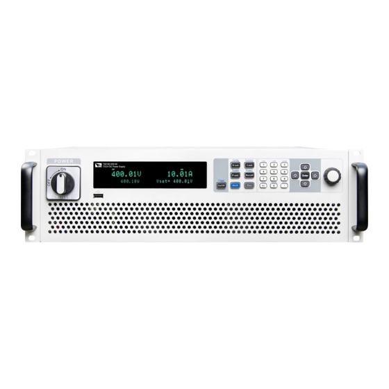
1.2 Front-Panel Overview For the IT6000D series High power Programmable DC Power Supply, all front panels of the 3U model are the same, and the operation panels of other models are the same as those of the 3U model. The following is the front panel sche- matic of the 3U model. -
Page 15: Keyboard Introduction
Quick Reference 1.3 Keyboard Introduction The keyboard introduction of IT6000D series High power Programmable DC Power Supply is shown as follows. Keys Description [On/Off] Turn the power supply output on or off. When lit, indicates that the output is enabled or on. - Page 16 (Function) [Shift]+[P-set] Enter the System menu. (System) [Shift]+[Recall] Enter the Protect menu of the power supply (Protect) [Shift]+[1] (Log) Enter the data logging function menu. [Shift]+[2] (Lock) Turn the keyboard lock on or off. Copyright © Itech Electronic Co., Ltd.
-
Page 17: Push-On Knob
Save the common parameter settings. (Save) 1.4 Push-on Knob The IT6000D series High power Programmable DC Power Supply provides a knob on the front panel as shown in the next figure. The functions of the posh-on knob is described as follows. -
Page 18: Rear Panel Introduction
Quick Reference 1.5 Rear Panel Introduction The rear panel of the 3U model of the IT6000D series High power Program- mable DC Power Supply (after removing the protective cover) is shown below. The rear panel of the 6U model is the same as the 3U model. -
Page 19: Vfd Indicator Lamps Description
11. AC power input terminals (L1, L2, L3, and PE) 12. Chassis ground terminal 1.6 VFD Indicator Lamps Description The IT6000D series High power Programmable DC Power Supply VFD indica- tor lamps description is as follows: Table 1–1 VFD Indicator Lamps Description... -
Page 20: Configuration Menu Function
Quick Reference 1.7 Configuration Menu Function This section gives an overview of the configuration menu of the IT6000D series power supply. The procedures to operate the configuration menu are as follows. 1. Press the composite keys [Shift]+[V-set] (Config) on the front panel to enter the configuration menu. -
Page 21: System Menu Function
1.8 System Menu Function This Chapter offers a general introduction of system menus, allowing users to have a preliminary understanding of system functions of this IT6000D series. The steps of the system menu function are as follows: 1. Press the composite keys [Shift]+[P-set] (System) on the front panel to en- ter the system menu. - Page 22 Virtual LAN communication. After selecting this option, you also need to set the commu- nication parameters of the LAN, and the menu items are the same as those in the LAN menu (see below). LAN communication interface Copyright © Itech Electronic Co., Ltd.
- Page 23 If it is not in- volved, there is no need to set it. • Socket Port: 30000 Set the port number. Configure the LAN services. Serv-Conf MDNS: MDNS service state. • • Copyright © Itech Electronic Co., Ltd.
- Page 24 Baud rate: 4800/9600/19200/38400/57600/ Baudrate ing to optional in- 115200 terface. In Databit Data bit: 5/6/7/8 addition, RS232 interface and the Parity bit: N (No parity) / E (Even parity) / O Parity analog interface (Odd parity) Copyright © Itech Electronic Co., Ltd.
- Page 25 Used to control whether the voltage is quickly zeroed after the output is turned off. System Rzero • Off: No • On: Yes View the system information. For details, see 5.14 View the System In- System Info formation (System Info). Copyright © Itech Electronic Co., Ltd.
-
Page 26: Options Introduction
Quick Reference 1.9 Options Introduction The IT6000D series High power Programmable DC Power Supply supports the following two types of optional accessories (sold separately), the details are as below: • Optional interface card – IT-E166: Interface card for GPIB communication. When users need to use GPIB communication, they can choose to purchase this accessory. - Page 27 – IT-E168: Used for parallel connection between the units in a cabinet, in- cluding one fiber module and two fiber cables. – IT-E169: Used for parallel connection between cabinets, including one fi- ber module and one 2.5m fiber cable. Copyright © Itech Electronic Co., Ltd.
-
Page 28: Inspection And Installation
Connecting the Power Cord. USB communication This accessory is se- cable lected when the USB in- terface is used for starting up remote operation. It contains User Manual, Programming Guide and other user documentations. Copyright © Itech Electronic Co., Ltd. -
Page 29: Instrument Size Introduction
2.2 Instrument Size Introduction The instrument should be installed at well-ventilated and rational-sized space. Please select appropriate space for installation based on the instrument size. The detailed dimension drawings of the IT6000D series are as follows: Copyright © Itech Electronic Co., Ltd. - Page 30 Inspection and Installation 3U Models 3U Slave Models Copyright © Itech Electronic Co., Ltd.
-
Page 31: Connecting The Power Cord
Categories of Power Cords The standard power cord specifications for this series of 3U instruments are shown below: Copyright © Itech Electronic Co., Ltd. - Page 32 2. Confirm that the power switch is in the OFF position and verify that there is no dangerous voltage on the connection terminals. 3. Remove the protective cover outside the AC input terminal on the rear panel. Copyright © Itech Electronic Co., Ltd.
-
Page 33: Connecting The Device Under Test (Dut)
2.4 Connecting the Device Under Test (DUT) This section describes how to connect the test cables between the instrument and DUT. Precautions To prevent electric shock and damage to the instrument, observe the following precautions. Copyright © Itech Electronic Co., Ltd. - Page 34 Short circuit may cause severe accident. • Always use test cables provided by ITECH to connect the equip- ment. If test cables from other factories are used, please confirm the maximum current that the test cables can withstand.
- Page 35 The connection diagram and steps of remote measurement are as follows: Copyright © Itech Electronic Co., Ltd.
- Page 36 Lethal voltages may remain at the output terminals after turn-off. Verify that there is no dan- gerous voltage on the output or sense terminals before touching them. Copyright © Itech Electronic Co., Ltd.
-
Page 37: Remote Interface Connection
• VCP: Virtual serial port. Select this type, you need to install the correspond- ing driver. Please contact ITECH Technical Support for the driver. • LAN: USB-LAN interface, which is a virtual network port. After selecting this option, you also need to set the communication parame- ters of the LAN, and the menu items are the same as those in the LAN menu. -
Page 38: Lan Interface
When the instrument and computer are connected to the router, an independent IP address must be assigned for the instrument. View LAN Interface Information The operation steps to view the LAN interface information in the System Menu are as follows. Copyright © Itech Electronic Co., Ltd. - Page 39 1.8 System Menu Function for details. Configure LAN Interface Information The configurable parameters of the IT6000D series power supply are described as follows. IP-Conf • IP: This value is the Internet Protocol (IP) address of the instrument. An IP address is required for all IP and TCP/IP communications with the instru- ment.
- Page 40 5. Rotate the knob to select the service you want to enable and press [Enter]. 6. Rotate the knob to select whether to enable the service and press [Enter]. – On: Indicates that the service is enabled. – Off: Indicates that the service is disabled. Copyright © Itech Electronic Co., Ltd.
- Page 41 The detailed descriptions are as follows. • Home:Web home interface, displays the model and appearance of the instrument; • Information: Displays the serial number of the instrument and more system information as well as LAN configuration parameters; Copyright © Itech Electronic Co., Ltd.
-
Page 42: Can Interface
This page allows you to monitor and control the instrument; • LAN Configuration: Reconfigure the LAN parameters; • Manual: Go to the ITECH official website and view or download the relevant documents. • Upload: Performs a system upgrade. Click CONNECT to connect the PC with the instrument, then click Select File to select the system upgrade installation package (for example, itech_6000_P.itech), and then click UPLOAD performs the upgrade op-... - Page 43 PC and the instrument must have the same baud rate. • Ensure you have used the correct communication cable (CAN_H, CAN_L). Please pay attention that some cable may not have a correct internal wiring even it is with an appropriate plug. Copyright © Itech Electronic Co., Ltd.
-
Page 44: Gpib Interface (Optional)
GPIB address appears in the System menu. The specific steps are as follows: 1. Ensure that the instrument's power switch is off, that is, the instrument is in Power Off state. Copyright © Itech Electronic Co., Ltd. -
Page 45: Interface (Optional)
When you purchase the interface accessory and successfully insert it into the corresponding position on the rear panel of the instrument, the RS–232 menu item will appear in the System menu. The specific steps are as follows: Copyright © Itech Electronic Co., Ltd. - Page 46 Make sure the correct cable and adapter are connected. Note that internal wiring may not be correct even if the cable has a suitable plug; • The cable must be connected to the correct serial ports (COM1, COM2, etc) of PC. Copyright © Itech Electronic Co., Ltd.
-
Page 47: Getting Started
When you turn the POWER switch on for the first time after purchase, the instru- ment starts with its factory default settings. Each time thereafter, the instrument starts according to the setting that you selected as outlined in 5.6 Set the Power-on State (PowerOn). Copyright © Itech Electronic Co., Ltd. - Page 48 The status of Power switch is as follows. If the instrument is the cabinet type, the rear panel of the cabinet provides a master power switch. The relationships between the device status and switch status are listed in the following table. Copyright © Itech Electronic Co., Ltd.
- Page 49 Error message Error Description Eeprom Failure The EEPROM is damaged. Main FrameInitializeLost The system setting data is lost. Calibration Data Lost The factory calibration data in EE- PROM is lost. Copyright © Itech Electronic Co., Ltd.
-
Page 50: Set Output Value
2.3 Connecting the Power Cord to select proper AC input. 4. If you need additional assistance, contact ITECH technical support engineer. 3.2 Set Output Value The voltage value, current value, power value can all be programmed. The user can set different output parameters within the range of specifications according to the need to satisfy a range of test requirement. -
Page 51: Use The Front Panel Menu
When the number in front of the menu item is blinking, indicates this item is selected currently. Press [Enter] key to enter the selected menu item and press [Esc] to exit the menu. Copyright © Itech Electronic Co., Ltd. -
Page 52: On/Off Control
DUT. If the power supply has no output after the output is turned on, check the voltage and current setting value, set the voltage and current to a non-zero value, and then turn on the output. Copyright © Itech Electronic Co., Ltd. -
Page 53: Power Supply Function
When [I-set] key is pressed, the key light is lit and the output current value can be set. Press numeric keys or rotate the knob to adjust the value in the current setting area indicated by the cursor. This value takes effect when you press [Enter]. Copyright © Itech Electronic Co., Ltd. -
Page 54: Set The Output Power
A current limit value should also be set. The current limit should always be set to a value that is greater than the actual input current requirement of the external load. The following figure shows the CV priority operating locus of the output. Copyright © Itech Electronic Co., Ltd. - Page 55 The following figure shows the CC priority oper- ating locus of the output. Copyright © Itech Electronic Co., Ltd.
- Page 56 5. Press the down arrow key to set the voltage/current rise time. When finished, press [Enter]. 6. Set the other Config menu items in the same way. 7. Set the output voltage and current value. • CV priority Copyright © Itech Electronic Co., Ltd.
-
Page 57: Set The Internal Resistance
Vlim, and the voltage lower limit is 0. 4.4.2 Set the Internal Resistance The IT6000D series power supply provides internal resistance setting (CV prior- ity mode only). The procedures are shown as below. 1. Press the composite keys [Shift]+[V-set] (Config) on the front panel to enter the configuration menu. - Page 58 Turn the UCP function on. Indicates the instrument warm-up time. This time is set to prevent the in- strument from triggering Warm-up protection when the cur- rent is rising. Because this transient condition should not be Copyright © Itech Electronic Co., Ltd.
- Page 59 Specifying an protection delay (Delay) can ignore these momentary changes during the specified delay period. Once the delay time has expired and the protection limit condition persists, the output will shut down. Copyright © Itech Electronic Co., Ltd.
- Page 60 After the protection is cleared, you need to press the [On/Off] key on the front panel or send the OUTPut ON command to the instrument to reopen [On/Off]. Copyright © Itech Electronic Co., Ltd.
-
Page 61: Set Over-Voltage Protection (Ovp)
150V, 1S 4.5.2 Set Over-Current Protection (OCP) Users can enable the OCP function and set the protection limit Level and pro- tection delay time Delay. When the current (i.e., the Meter value) is greater than Copyright © Itech Electronic Co., Ltd. -
Page 62: Set Over-Power Protection (Opp)
Many reasons can cause OPP, the details are as follows: • The set protection limit Level is lower than the power Meter value. • The power supply outputs a high power due to a fault. Copyright © Itech Electronic Co., Ltd. -
Page 63: Set Under-Current Protection (Ucp)
2. Press the up/down key or rotate the knob to select 4. UCP (Off) and press [Enter]. 3. Press the left/right key or rotate the knob to select On and press [Enter] to enter the setting interface. Copyright © Itech Electronic Co., Ltd. -
Page 64: Set Under-Voltage Protection (Uvp)
[Enter] to confirm. The VFD screen returns to the Protect menu and the UVP setting (take 10S, 1V, 1S as an example) is displayed as follows: PROTECT 5.UVP 10S, 1V, 1.000S Copyright © Itech Electronic Co., Ltd. -
Page 65: Over-Temperature Protection (Otp)
When you return power to the instrument, verify that the cooling fan is running. If not, please contact ITECH Technical Support. Leaving the instrument powered on with an inoperative cooling fan may result in damage to the instrument. -
Page 66: Function Menu For Power Supply
Function). 4.6.1 LIST Function The IT6000D series power supply supports a total of 10 List files (List01 to List10), each of which can be set up to 200 steps. You need to edit the voltage/ current value, slope and time width of each step, or you can set repeat times (1 to 65535) for each List file. - Page 67 Last After the List program finishes run- ning, the output is kept as the set- ting in the last step, and the working mode remains as the set- ting in the List file. Copyright © Itech Electronic Co., Ltd.
- Page 68 9. Set the End State as Normal, and press [Enter] to confirm. 10. Depending on the test requirement, choose whether to turn on the function switch that triggers synchronization. 11. Set the currently edited List program name. Copyright © Itech Electronic Co., Ltd.
- Page 69 The procedures are as follows: 1. Press the composite keys [Shift]+[I-set] (Function) on the front panel to en- ter the function menu. 2. Select 1. LIST: Off and press [Enter]. Copyright © Itech Electronic Co., Ltd.
- Page 70 You can select a List file to execute according to your needs, so that the power supply outputs the corresponding waveform sequence. Take the List file in Internal as an example. The steps are as follows: Copyright © Itech Electronic Co., Ltd.
- Page 71 Function menu item will be displayed, you can re-enter the Function menu for editing; if Reset is selected, it means to stop the present run- ning and return to the main interface to wait for the next trigger operation. Copyright © Itech Electronic Co., Ltd.
-
Page 72: Battery Charging Test Function
Power Supply Function 4.6.2 Battery Charging Test Function The IT6000D series power supply provides the battery charging test function. Suitable for charging tests on all types of portable batteries. Battery charging test function BATTERY Indicates that the battery test mode is entered and waits to trigger the running of the currently edited bat- tery test file. - Page 73 Function menu item will be displayed, you can re-enter the Function menu for editing; if Reset is selected, it means to stop the present run- ning and return to the main interface to wait for the next trigger operation. Copyright © Itech Electronic Co., Ltd.
-
Page 74: Basic Operation
This function can prevent the power supply from the panel keys misoperation during usage. Press the composite keys [Shift]+[2] (Lock) to lock front panel keys and the lock symbol “*” is shown on the front panel display. All panel keys, Copyright © Itech Electronic Co., Ltd. -
Page 75: Save And Recall Operations
You can do the save and recall operations by the following two methods. • Press the composite keys [Shift]+[+/-] (Save) to save the parameters. Press the [Recall] key to recall the parameters. • SCPI commands: *SAV and *RCL Copyright © Itech Electronic Co., Ltd. -
Page 76: Save Operation
3. Press [Enter] to recall the parameters. 5.4 Data Logging Function The IT6000D series High power Programmable DC Power Supply supports the recording and saving of test data. This Chapter introduces how to use this func- tion in details. - Page 77 2. Set the value of Sample Period and press [Enter]. 3. Set the value of Duration and press [Enter]. Copyright © Itech Electronic Co., Ltd.
- Page 78 Trig-In→Dlog to trigger. For details, see 5.11.4 IO–4. Ext-Trig, Not-Invert. After the data recording function is started, the lower right corner of the main in- terface displays Logging, indicating that the data is recorded. The recorded Copyright © Itech Electronic Co., Ltd.
-
Page 79: Set The Beeper Status (Beep)
The detailed power-on parameters and output state are as follows. • The voltage, current, power setting values displayed on the main interface when the instrument is powered on. • Parameter setting values in the Config menu. Copyright © Itech Electronic Co., Ltd. - Page 80 Upper limit of current: Ilim One percent of the rated current of the instrument Upper limit of power: Plim Rated power value of the instrument [On/Off] status Config Mode menu Speed High Copyright © Itech Electronic Co., Ltd.
-
Page 81: Sense Function (Sense)
This menu item is used to switch the power supply to local measurement or re- mote sensing. The IT6000D series power supply supports two connection methods: Local measurement and Remote sensing. The remote sensing is used for maximizing measurement accuracy. (Refer to 2.4 Connecting the Device Under Test... -
Page 82: Select Trigger Source (Trig Source)
Basic Operation 5.8 Select Trigger Source (Trig Source) For the IT6000D series power supply, the List and data logging functions can be triggered for running by the following methods: • Manual: Default value, indicates the trigger occurs when the [Shift]+[On/Off] (Trigger) keys are pressed from the front panel. -
Page 83: Set Parallel Operation Mode (Parallel)
The IT6000D series power supply supports multiple instruments to work in par- allel mode to provide more power and current output capability. - Page 84 Instruction or the IT6000 Cabinet Assembly Instruction. 1. Ensure that the power switches of the three units and the main switch of the AC power distribution box are off. 2. Refer Figure 5–1 Wiring connection diagram to connect three units. Copyright © Itech Electronic Co., Ltd.
- Page 85 Black indicates the wiring of the inner ring of the fiber, and red indicates the wiring of the outer ring of the fiber. 3. Turn on the main switch of the AC distribution box and power on each of the three units. Copyright © Itech Electronic Co., Ltd.
-
Page 86: Digital I/O Function (Digital Port)
5.11 Digital I/O Function (Digital Port) The IT6000D series power supply supports digital I/O function. The user can realize logic control over high and low level input or output by related configura- tions in the system menu, namely general digital signal I/O function. In addition to general digital I/O functions, this series can be customized to meet different special needs through different pin wirings. - Page 87 Typical high level output voltage Typical low level current 0.5mA Minimum high level input 1.6V voltage Level rise slope 10us Level fall slope Pins Introduction The appearance of the terminals are shown below. Copyright © Itech Electronic Co., Ltd.
- Page 88 5.11.5 IO–5. INH-Living, Not-Invert. Corresponds to the function set in the Pulse signal Level or PWM System→Digital Port→IO–6. Sync- signal On, Not-Invert menu item. For pa- rameter introduction, see 5.11.6 IO– 6. Sync-On, Not-Invert. Copyright © Itech Electronic Co., Ltd.
- Page 89 Output→PWM, the user needs to set the frequency (PWM Freq) and du- ty cycle (PWM Duty) values. For example, if the PWM Freq is set to 100Hz and the PWM Duty is set to 10%, the output waveform is as follows: Copyright © Itech Electronic Co., Ltd.
-
Page 90: Io-1. Ps-Clear, Not-Invert
Indicates whether to invert the input/output Invert pulse or level signal. • Invert: Yes Invert • Not-Invert: No This default function means that when Clear the instrument generates protection, the protection state can be cleared via this pin. Copyright © Itech Electronic Co., Ltd. - Page 91 Pulse input: When the instrument is under protection, the instrument will clear protection after receiving the pulse signal from external input. 1. Refer to the figure below to connect pin 1 to the external oscilloscope. Copyright © Itech Electronic Co., Ltd.
-
Page 92: Io-2. Ps, Not-Invert
5.11.2 IO–2. Ps, Not-Invert Parameter Description IO–2. Ps, Not- Parameter setting for pin 2. Invert Not- Indicates whether to invert the input/output Invert pulse or level signal. • Invert: Yes Invert • Not-Invert: No Copyright © Itech Electronic Co., Ltd. - Page 93 2 outputs high level; when the instrument is under protection, pin 2 outputs low level. When pin 2 is set to Invert, the output level is completely opposite. 1. Refer to the figure below to connect pin 2 to the external oscilloscope. Copyright © Itech Electronic Co., Ltd.
-
Page 94: Io-3. Off-Status, Not-Invert
Pin 3 receives the level signal from the outside. Output Pin 3 sends the digital signal (1, 0, PWM) to the outside. True By default (Not-Invert), the out- put digital signal is 1 (i.e. low Copyright © Itech Electronic Co., Ltd. - Page 95 1. Refer to the figure below to connect pin 3 to the external oscilloscope. 2. Confirm that pin 3 function is set to the default option, namely IO-3. Off-Status, Not-Invert. 3. Turn on [On/Off]. 4. Check the oscilloscope and confirm that pin 3 outputs low level. Copyright © Itech Electronic Co., Ltd.
-
Page 96: Io-4. Ext-Trig, Not-Invert
This function needs to be triggered at the upper com- puter side through SCPI in- struction. For de- tails, refer to instructions re- lated to ACQuire in the Trigger subsystem of the Instruction Manual. Copyright © Itech Electronic Co., Ltd. - Page 97 Taking the triggering of List function as an example, the text below will introduce how to use pin 4’s default function Ext-Trig. • Trig–Out 1. Refer to the figure below to connect pin 4 to the external oscilloscope. Copyright © Itech Electronic Co., Ltd.
- Page 98 5. Check the oscilloscope and confirm whether pin 4 has following pulse signal output. Level rise slope 10us Level fall slope Minimum time width 30us for low level keep • Trig-In 1. Refer to the figure below to connect pin 4 to the external oscilloscope. Copyright © Itech Electronic Co., Ltd.
-
Page 99: Io-5. Inh-Living, Not-Invert
List file is running or not. 5.11.5 IO–5. INH-Living, Not-Invert Parameter Description IO–5. Living, Parameter setting for pin 5. Not-Invert Not- Indicates whether to invert the input/output pulse or Invert level signal. • Invert: Yes Invert • Not-Invert: No Copyright © Itech Electronic Co., Ltd. - Page 100 The [On/Off] button light is lighted on and VFD still displays On, but the actual output is 0; when pin 5 receives high level sig- nal again, the output state is recovered. Copyright © Itech Electronic Co., Ltd.
- Page 101 The pa- rameter requirements of this pulse signal are as follows: Level rise slope 10us Level fall slope Minimum time width 30us for low level keep Copyright © Itech Electronic Co., Ltd.
-
Page 102: Io-6. Sync-On, Not-Invert
When the protection state is cleared, manually turn on [On/Off] again. 5.11.6 IO–6. Sync-On, Not-Invert Parameter Description IO–6. Sync- Parameter setting for pin 6. On, Not- Invert Not- Indicates whether to invert the input/output pulse or Invert level signal. Copyright © Itech Electronic Co., Ltd. - Page 103 The parameter requirements of this pulse signal are as follows: Level rise slope 10us Level fall slope Minimum time width 30us for low level keep The bi-direction I/O functions are introduced as below: Copyright © Itech Electronic Co., Ltd.
-
Page 104: Io-7. Sync-Off, Not-Invert
B’s output function is synchronously turned on. 5.11.7 IO–7. Sync-Off, Not-Invert Parameter Description IO–7. Sync-Off, Parameter setting for pin 7. Not-Invert Not- Indicates whether to invert the input/output pulse Invert or level signal. Copyright © Itech Electronic Co., Ltd. - Page 105 The parameter requirements of this pulse signal are as follows: Level rise slope 10us Level fall slope Minimum time width 30us for low level keep The bi-direction I/O functions are introduced as below: Copyright © Itech Electronic Co., Ltd.
-
Page 106: Analogue Function (Ext-Program) (Optional)
The external analog function controls the actual output voltage/current value of the instrument by inputting a voltage between –10V and 10V to the specified pin, and limits the output of the voltage/current to a specified range. Copyright © Itech Electronic Co., Ltd. - Page 107 Indicates the offset of channel 2. Set the parameters of channel 3 (lower limit channel). For the IT6000D series of unipolar power supplies, the voltage/current lower limit does not need to be specified. Therefore, the Ch3 parameters here do not need to be set.
- Page 108 CC priority: Specify the value of the voltage upper limit Vlim. The setting for the voltage/current lower limit corresponds to Ch3 in the menu. (IT6000D series models do not need to be set) Analog Conversion Relationship Introduction Taking the Ch1 programming channel as an example, the user needs to convert the values of Mx and Mb according to the following formulas, and then set the two values through the front panel keys or SCPI remote commands.
- Page 109 The end value of the output current in CC out2 priority mode, and I >I out2 out1 • CV priority • CC priority How to Use The following takes the CV priority mode as an example to introduce the usage steps. Copyright © Itech Electronic Co., Ltd.
- Page 110 7. Adjust the output of DC Power Supply 1 from -5V to 5V, and adjust the out- put of DC Power Supply 2 from -10V to 10V. The actual output voltage and current of the instrument will change accord- ing to the following rules: Copyright © Itech Electronic Co., Ltd.
-
Page 111: Restored To Factory Setting (System Reset)
Upper limit of voltage: Vlim Upper limit value: One percent of the rated volt- age of the instrument Upper limit of current: Ilim One percent of the rated current of the instrument Copyright © Itech Electronic Co., Ltd. - Page 112 30000 LAN→Serv-Conf MDNS/PING/Telnet- scpi/Web/VX-11/ Raw-socket: On • VCP: 9600,8,N,1 • (Optional) RS232: 9600,8,N,1 • (Optional) External analog: Off • (Optional) GPIB: Ad- dress=1 • Digital Port IO–1: Ps-Clear • IO–2: Ps • IO–3: Off-Status Copyright © Itech Electronic Co., Ltd.
-
Page 113: View The System Information (System Info)
1. Press the composite keys [Shift]+[P-set] (System) on the front panel to en- ter the system menu. 2. Press the Up/Down key or turn the knob to select the System Info and press [Enter]. Copyright © Itech Electronic Co., Ltd. -
Page 114: System Upgrade
Run Time Display the power-on time. 5.15 System Upgrade The IT6000D series power supply supports the upgrade of the system version. System upgrade includes the following two methods: • During the start-up period after the instrument is powered on, through the USB interface on the front panel, select the system upgrading files in the memory device (USB flash drive) for upgrading. - Page 115 For example, when there are multiple system upgrading package post- fixed with .itech in the root directory of your USB flash drive, you need to use a text editing tool to open the configuration file and specify the up- grade package name corresponding to the present upgrade operation.
- Page 116 After the system upgrading files are detected, the interface displays as follows: Update Select(xx/yy) SN: ALL xx means the number of selected instruments to be upgraded, and yy means the number of instruments in the parallel network. Copyright © Itech Electronic Co., Ltd.
- Page 117 The system will automatically perform upgrading. If No is selected, it means to exit upgrading, and the system will di- rectly enter into the main interface. 5. After the upgrading is completed, you need to restart the instrument manually. Copyright © Itech Electronic Co., Ltd.
-
Page 118: Technical Specification
This chapter will introduce the main technical parameters of thispower, such as rated voltage/current/power and so on. Besides, we will introduce the working environment and storage temperature. ♦ Main Specification ♦ Supplemental Characteristics 6.1 Main Specification Copyright © Itech Electronic Co., Ltd. -
Page 119: It6006D-500-30
(%of Output/℃+Offset) Current ≤200PPM/℃ Read Back Temperature Voltage ≤50PPM/℃ Coefficient (%of Output/℃+Offset) Current ≤200PPM/℃ Rise time( no load ) Voltage ≤15ms Rise time( full load ) Voltage ≤30ms Fall time( no load ) Voltage ≤1s Copyright © Itech Electronic Co., Ltd. - Page 120 Standard: USB, CAN, LAN; optional: GPIB, analog card, fiber Communication interface optic socket Isolation (output to ground) 1000V Working temperature 0 to 50℃ Number of series and ≤1 parallel units Dimension (mm) 483W*801.61D*151.3H Weight (net) 28KG Copyright © Itech Electronic Co., Ltd.
-
Page 121: It6012D-500-60
(%of Output/℃+Offset) Current ≤200PPM/℃ Read Back Temperature Voltage ≤50PPM/℃ Coefficient (%of Output/℃+Offset) Current ≤200PPM/℃ Rise time( no load ) Voltage ≤15ms Rise time( full load ) Voltage ≤30ms Fall time( no load ) Voltage ≤1s Copyright © Itech Electronic Co., Ltd. - Page 122 Standard: USB, CAN, LAN; optional: GPIB, analog card, fiber Communication interface optic socket Isolation (output to ground) 1000V Number of series and ≤1 parallel units Working temperature 0 to 50℃ Dimension (mm) 483W*801.61D*151.3H Weight (net) 34KG Copyright © Itech Electronic Co., Ltd.
-
Page 123: It6018D-500-90
(%of Output/℃+Offset) Current ≤200PPM/℃ Read Back Temperature Voltage ≤50PPM/℃ Coefficient (%of Output/℃+Offset) Current ≤200PPM/℃ Rise time( no load ) Voltage ≤15ms Rise time( full load ) Voltage ≤30ms Fall time( no load ) Voltage ≤1s Copyright © Itech Electronic Co., Ltd. - Page 124 Standard: USB, CAN, LAN; optional: GPIB, analog card, fiber Communication interface optic socket Isolation (output to ground) 1000V Working temperature 0 to 50℃ Number of parallel units ≤8 483W*801.61D*151.3H Dimension (mm) 40kg Weight (net) Copyright © Itech Electronic Co., Ltd.
-
Page 125: It6018D-1500-30
(%of Output/℃+Offset) Current ≤200PPM/℃ Read Back Temperature Voltage ≤50PPM/℃ Coefficient (%of Output/℃+Offset) Current ≤200PPM/℃ Rise time( no load ) Voltage ≤15ms Rise time( full load ) Voltage ≤30ms Fall time( no load ) Voltage ≤1s Copyright © Itech Electronic Co., Ltd. - Page 126 Standard: USB, CAN, LAN; optional: GPIB, analog card, fiber Communication interface optic socket Isolation (output to ground) 1800V Working temperature 0 to 50℃ Number of parallel units ≤8 483W*801.61D*151.3H Dimension (mm) 40KG Weight (net) Copyright © Itech Electronic Co., Ltd.
-
Page 127: It6006D-800-20
(%of Output/℃+Offset) Current ≤200PPM/℃ Read Back Temperature Voltage ≤50PPM/℃ Coefficient (%of Output/℃+Offset) Current ≤200PPM/℃ Rise time( no load ) Voltage ≤15ms Rise time( full load ) Voltage ≤30ms Fall time( no load ) Voltage ≤1s Copyright © Itech Electronic Co., Ltd. - Page 128 Standard: USB, CAN, LAN; optional: GPIB, analog card, fiber Communication interface optic socket Isolation (output to ground) 1000V Number of series and ≤1 parallel units Working temperature 0 to 50℃ Dimension (mm) 483W*801.61D*151.3H Weight (net) 28KG Copyright © Itech Electronic Co., Ltd.
-
Page 129: It6012D-800-40
(%of Output/℃+Offset) Current ≤200PPM/℃ Read Back Temperature Voltage ≤50PPM/℃ Coefficient (%of Output/℃+Offset) Current ≤200PPM/℃ Rise time( no load ) Voltage ≤15ms Rise time( full load ) Voltage ≤30ms Fall time( no load ) Voltage ≤1s Copyright © Itech Electronic Co., Ltd. - Page 130 Standard: USB, CAN, LAN; optional: GPIB, analog card, fiber Communication interface optic socket Isolation (output to ground) 1500V Number of series and ≤1 parallel units Working temperature 0 to 50℃ Dimension (mm) 483W*801.61D*151.3H Weight (net) 34KG Copyright © Itech Electronic Co., Ltd.
-
Page 131: It6018D-800-60
(%of Output/℃+Offset) Current ≤200PPM/℃ Read Back Temperature Voltage ≤50PPM/℃ Coefficient (%of Output/℃+Offset) Current ≤200PPM/℃ Rise time( no load ) Voltage ≤15ms Rise time( full load ) Voltage ≤30ms Fall time( no load ) Voltage ≤1s Copyright © Itech Electronic Co., Ltd. -
Page 132: It6018D-2250-20
Standard: USB, CAN, LAN; optional: GPIB, analog card, fiber Communication interface optic socket Isolation (output to ground) 1500V Working temperature 0 to 50℃ 483W*801.61D*151.3H Dimension (mm) Weight (net) 40KG 6.1.8 IT6018D-2250-20 Parameters IT6018D-2250-20 Output Rating Output Voltage 0 to 2250V Copyright © Itech Electronic Co., Ltd. - Page 133 Rise time( full load ) Voltage ≤30ms Fall time( no load ) Voltage ≤1s Fall time( full load ) Voltage ≤100ms Transient Response Time Voltage ≤2ms 198V to 264V(Derating 50%) 342V to AC Input Voltage 528V (Three-phase four-wire) Copyright © Itech Electronic Co., Ltd.
- Page 134 Standard: USB, CAN, LAN; optional: GPIB, analog card, fiber Communication interface optic socket Isolation (output to ground) 3000V Working temperature 0 to 50℃ Number of parallel units ≤8 483W*801.61D*151.3H Dimension (mm) 40KG Weight (net) Copyright © Itech Electronic Co., Ltd.
-
Page 135: Supplemental Characteristics
Technical Specification 6.2 Supplemental Characteristics State storage capacity: 10 sets Recommended calibration frequency: once a year Cooling style: fans Copyright © Itech Electronic Co., Ltd. -
Page 136: A Appendix
♦ Fuse Replacement A.1 Specifications of Red and Black Test Cables ITECH provides you with optional red and black test cables, which are sold indi- vidually and you can select for test. For specifications of ITECH test cables and maximum current values, refer to the table below. -
Page 137: Fuse Replacement
If there are no fuse assembly on the instrument rear panel, it means that you can’t replace the fuse by yourself. Please contact the ITECH engineer on the condition of the same malfunction. - Page 138 2. Have a visual inspection of the fuse to see whether it is burnt out; if yes, replace it with another fuse of the same specification. Re- fer to the corresponding technical specifi- cations for fuse rating. Copyright © Itech Electronic Co., Ltd.
- Page 139 3. Please replace with a fuse of the same specification. Refer to the technical specifi- cation of the corresponding instrument. 4. When install, put into the fuse box firstly. Then Push and turn the fuse box to 90 de- grees clockwise. Copyright © Itech Electronic Co., Ltd.
- Page 140 Contact Us Thanks for purchasing ITECH products. In case of any doubts, please con- tact us as follows: 1. Refer to accompanying data disk and relevant manual. 2. Visit ITECH website: www.itechate.com. 3. Select the most convenient contact method, for further information.
Need help?
Do you have a question about the IT6000D Series and is the answer not in the manual?
Questions and answers