
Related Manuals for ITech IT6000B Series


Summary of Contents for ITech IT6000B Series
- Page 1 Via Acquanera, 29 22100 Como tel. 031.526.566 (r.a.) fax 031.507.984 info@calpower.it www.calpower.it Regenerative Power System IT6000B Series User Manual Model: IT6000B Series Version: V1.2/11,2019...
- Page 2 CAUTION sign until the in- pose. ITECH shall not be held liable Manual Part Number dicated conditions are for errors or for incidental or indirect fully understood and met.
-
Page 3: Warranty
Warranty ITECH warrants that the product will be free from defects in material and work- manship under normal use for a period of one (1) year from the date of delivery (except those described in the Limitation of Warranty below). -
Page 4: Safety Symbols
Failure to comply with these precautions or specific warn- ings elsewhere in this manual will constitute a default under safety standards of design, manufacture and intended use of the instrument. ITECH assumes no li- ability for the customer’s failure to comply with these precautions. - Page 5 This instrument is used for industrial purposes, do not apply this product to IT power supply system. • Never use the instrument with a life-support system or any other equip- ment subject to safety requirements. Copyright © Itech Electronic Co., Ltd.
-
Page 6: Environmental Conditions
Make sure the vent hole is always unblocked. Environmental Conditions The instrument is designed for indoor use and an area with low condensation. The table below shows the general environmental requirements for the instrument. Copyright © Itech Electronic Co., Ltd. -
Page 7: Regulation Tag
The service life of the product is 10 years. The product can be used safely within the environmental protection period; otherwise, the product should be put into the recycling system. Copyright © Itech Electronic Co., Ltd. -
Page 8: Waste Electrical And Electronic Equipment (Weee) Directive
According to the equipment classifi- cation in Annex I of the WEEE direc- tive, this instrument belongs to the “Monitoring” product. If you want to return the unnecessary instrument, please contact the near- est sales office of ITECH. Copyright © Itech Electronic Co., Ltd. -
Page 9: Compliance Information
2. Connection of the instrument to a test object may produce radiations beyond the specified limit. 3. Use high-performance shielded interface cable to ensure conformity with the EMC standards listed above. Safety Standard IEC 61010-1:2010+A1:2016 Copyright © Itech Electronic Co., Ltd. -
Page 10: Table Of Contents
4.5.5 Set Under-Voltage Protection (UVP)............65 4.5.6 Over-Temperature Protection (OTP)............65 4.5.7 Sense Reverse Protection................66 4.6 Function Menu for Power Supply................67 4.6.1 LIST Function ....................67 4.6.2 Battery Charging/Discharging Test Function ..........73 Copyright © Itech Electronic Co., Ltd. VIII... - Page 11 6.17 Display Loading Time (Disp on timer)..............189 6.18 System Upgrade ....................189 7 Technical Specification ....................193 7.1 Main Specification....................193 7.1.1 IT6006C-500-30 ..................194 7.1.2 IT6012B-500-60..................198 7.1.3 IT6018B-500-90..................202 7.1.4 IT6006B-800-20..................206 7.1.5 IT6018B-800-60..................210 Copyright © Itech Electronic Co., Ltd.
- Page 12 8 Routine Maintenance ..................... 225 8.1 Instrument Self-Test..................... 225 8.2 Cleaning and Maintenance .................. 225 8.3 Contact of ITECH Engineers ................226 8.4 Return for Repair....................227 A Appendix ........................229 A.1 Specifications of Red and Black Test Cables ............. 229 A.2 Fuse Replacement ....................
-
Page 13: Quick Reference
♦ System Menu Function ♦ Options Introduction 1.1 Brief Introduction From the perspective of improving customer experience, ITECH launches a new incorporated product–IT6000B series. IT6000B integrates bidirectional power supply and regenerative electronic load into one 3U unit. It is also a very powerful one. - Page 14 Level IT6005B-80-120 120A IT6010B-80-240 240A 10KW IT6015B-80-360 360A 15KW IT6030B-80-720 720A 30kW IT6045B-80-1080 1080A 45kW IT6060B-80-1440 1440A 60kW IT6075B-80-1800 1800A 75kW IT6006B-500-40 IT6012B-500-80 12KW 500V IT6018B-500-120 120A 18KW IT6036B-500-240 240A 36kW IT6054B-500-360 360A 54kW Copyright © Itech Electronic Co., Ltd.
- Page 15 120A 36kW IT6054B-800-180 180A 54kW 800V IT6072B-800-240 240A 72kW IT6090B-800-300 300A 90kW IT6108B-800-360 360A 108kW IT6126B-800-420 420A 126kW IT6144B-800-480 480A 144kW IT6018B-1500-30 18KW IT6036B-1500-60 36kW 1500V IT6054B-1500-90 54kW IT6072B-1500-120 120A 72kW IT6090B-1500-150 150A 90kW Copyright © Itech Electronic Co., Ltd.
-
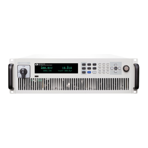
Page 16: Front-Panel Overview
90 model is 18,000W, and the maximum rated value of input power is also 18,000W. 1.2 Front-Panel Overview For the IT6000B series Regenerative Power System, all front panels of the 3U model are the same, and the operation panels of other models are the same as Copyright © Itech Electronic Co., Ltd. -
Page 17: Keyboard Introduction
3 Function and composite keys 7 Vent hole 4 Numeric and composite keys 8 USB storage device connection port 1.3 Keyboard Introduction The keyboard introduction of IT6000B series Regenerative Power System is shown as follows. Copyright © Itech Electronic Co., Ltd. - Page 18 Load mode: Set the input power value [R-set] Source mode: [R-set] key is not available Load mode: Set the resistance value [Shift] Composite key, combined with other keys to realize functions marked above keys. Copyright © Itech Electronic Co., Ltd.
- Page 19 Enter the data logging function menu. [Shift]+[2] (Lock) Turn the keyboard lock on or off. [Shift]+[3] (Local) Switch remote control mode to local control mode. [Shift]+[0] (Recall) Returns the instrument to the specified setup. Copyright © Itech Electronic Co., Ltd.
-
Page 20: Push-On Knob
[Shift]+[+/–] Save the common parameter settings. (Save) 1.4 Push-on Knob The IT6000B series Regenerative Power System provides a knob on the front panel as shown in the next figure. The functions of the posh-on knob is described as follows. •... -
Page 21: Rear Panel Introduction
Quick Reference 1.5 Rear Panel Introduction The rear panel of the 3U model of the IT6000B series Regenerative Power Sys- tem (after removing the protective cover) is shown below. The rear panel of the 6U model is the same as the 3U model. - Page 22 8. Communication interface of outer ring optical fiber (TX and RX) 9. DC output terminals of the power supply (or DC input terminals of the load) 10. AC power input terminals (L1, L2, L3, and PE) 11. Cabinet earthing rod Copyright © Itech Electronic Co., Ltd.
-
Page 23: Vfd Indicator Lamps Description
Quick Reference 1.6 VFD Indicator Lamps Description The IT6000B series Regenerative Power System VFD indicator lamps descrip- tion is as follows: Table 1–1 VFD Indicator Lamps Description Flag Function Flag Function Description Description Source mode: The Sense Sense function of the power output of the power system is enabled. -
Page 24: Configuration Menu Function
1.7 Configuration Menu Function This section gives an overview of the configuration menu of the IT6000B series power system. The configuration parameters are different under Source mode and Load mode, please select the mode at first. - Page 25 Once the voltage upper limit is Vmax modified here, the parameters related to the voltage setting will be limited by the upper limit here. The descriptions of configuration menu of the load are listed in the table below. Copyright © Itech Electronic Co., Ltd.
- Page 26 CP Mode) Set the power falling time. (only displayed P-Fall Slope under the CP Mode) Set Von function Latch Latch mode Level=0.00V Set the Von value Living Living mode Level=0.00V Set the Von value Copyright © Itech Electronic Co., Ltd.
-
Page 27: System Menu Function
1.8 System Menu Function This Chapter offers a general introduction of system menus, allowing users to have a preliminary understanding of system functions of this IT6000B series. The steps of the system menu function are as follows: 1. Press the composite keys [Shift]+[P-set] (System) on the front panel to en- ter the system menu. - Page 28 Gateway: 0.0.0.0 DNS1: 0.0.0.0 DNS2: 0.0.0.0 MAC: 8C:C8:F4:40:01:E1 MDNS Status: HostName: HostDesc: Domain: TCPIP:INSTR Socket Port: 30000 Configure LAN IP information. IP-Conf Configure LAN IP mode. IP-Mode Auto: automatically configure the address of the instrument. Copyright © Itech Electronic Co., Ltd.
- Page 29 MDNS: MDNS service state. • • PING: PING service state. • • Telnet-scpi: telnet-scpi service state. • • Web: Web service state. • • VX-11: VX-11 service state. • • Raw-socket: Raw-socket serv- ice state. • Copyright © Itech Electronic Co., Ltd.
- Page 30 When re-entering DigPort, the interface can display the changed option. For detailed introduction of menus and functions, see 6.11 Digital I/O Function (Digital Port). IO-1. Ps-Clear, Not- Function setting of pin 1 Invert Copyright © Itech Electronic Co., Ltd.
-
Page 31: Options Introduction
Screen displays loading time (Load mode only). Turn the display on. Turn the display off. 1.9 Options Introduction The IT6000B series Regenerative Power System supports the following two types of optional accessories (sold separately), the details are as below: • Optional interface card –... - Page 32 8 / 9 / Terminals for external analog function. For details, see 6.12 Source Analogue Function (Ext-Program) (Optional) 6.13 loadAnalogue Function (Ext-Program) (Optional). • Fiber optic modules and cables Copyright © Itech Electronic Co., Ltd.
- Page 33 – IT-E168: Used for parallel connection between the units in a cabinet, in- cluding one fiber module and two fiber cables. – IT-E169: Used for parallel connection between cabinets, including one fi- ber module and one 2.5m fiber cable. Copyright © Itech Electronic Co., Ltd.
-
Page 34: Inspection And Installation
Depending on the instru- ment model. For details, see 2.3 Con- necting the Power Cord. USB communication This accessory is se- cable lected when the USB in- terface is used for starting up remote operation. Copyright © Itech Electronic Co., Ltd. -
Page 35: Instrument Size Introduction
The instrument should be installed at well-ventilated and rational-sized space. Please select appropriate space for installation based on the instrument size. The detailed dimension drawings of the IT6000B series are as follows (unit: mm, deviation: ±1 mm): Copyright © Itech Electronic Co., Ltd. - Page 36 Inspection and Installation 3U Models Copyright © Itech Electronic Co., Ltd.
- Page 37 Inspection and Installation 6U Models Copyright © Itech Electronic Co., Ltd.
- Page 38 Inspection and Installation 15U Models Copyright © Itech Electronic Co., Ltd.
-
Page 39: Connecting The Power Cord
The 15U and 27U cabinets only show the size data. The number of instru- ments installed in the cabinet should be based on the actual model. 2.3 Connecting the Power Cord Precautions To prevent electric shock and damage to the instrument, observe the following precautions. Copyright © Itech Electronic Co., Ltd. - Page 40 L1, L2 and L3 terminals of power input on the rear panel of the in- strument; the yellow-green wire is grounding wire, which is connected to the PE terminal of power input on the rear panel. Copyright © Itech Electronic Co., Ltd.
- Page 41 The yellow-green wire is grounding wire, which is connected to the pro- tective grounding terminal (PE). 5. Mount the protective cover back to its original position. 6. Connect the other end of the power cable to the required AC distribution box. Copyright © Itech Electronic Co., Ltd.
-
Page 42: Connecting The Device Under Test (Dut)
2.4 Connecting the Device Under Test (DUT) This section describes how to connect the test cables between the instrument and DUT. Precautions To prevent electric shock and damage to the instrument, observe the following precautions. Copyright © Itech Electronic Co., Ltd. - Page 43 • Always use test cables provided by ITECH to connect the equipment. If test cables from other factories are used, please confirm the maximum current that the test cables can withstand.
- Page 44 DUT and output terminals of the power system. To maximize measurement accuracy, the power system provides the remote measurement terminals VS+ and VS- on the rear panel, which can be used to measure the terminal voltage of the DUT. Copyright © Itech Electronic Co., Ltd.
- Page 45 8. Connect the other end of the red and black cables to the DUT. The positive and negative poles must be properly connected and fastened when wiring. 9. Power on the instrument and turn on the Sense function of the instrument. For details, see 6.7 Sense Function (Sense). Copyright © Itech Electronic Co., Ltd.
-
Page 46: Remote Interface Connection
• VCP: Virtual serial port. Select this type, you need to install the correspond- ing driver. Please contact ITECH Technical Support for the driver. • LAN: USB-LAN interface, which is a virtual network port. After selecting this option, you also need to set the communication parame- ters of the LAN, and the menu items are the same as those in the LAN menu. -
Page 47: Lan Interface
They are typically large, centrally-managed networks with services such as DHCP and DNS servers. When connected to a computer, a network cable can be used to connect to the router, and the computer is also con- nected to the router. Copyright © Itech Electronic Co., Ltd. - Page 48 1.8 System Menu Function for details. Configure LAN Interface Information The configurable parameters of the IT6000B series power system are described as follows. IP-Conf • IP: This value is the Internet Protocol (IP) address of the instrument. An IP address is required for all IP and TCP/IP communications with the instru- ment.
- Page 49 Conf. • Serv-Conf 1. Press the composite keys [Shift]+[P-set] (System) on the front panel to enter the system menu. 2. Rotate the knob or press the Up/Down key to select I/O and press [Enter]. Copyright © Itech Electronic Co., Ltd.
- Page 50 The format of the address entered in the address bar of the browser is http:// 192.168.0.100. The specific IP address is subject to the actual instrument settings. The opened page is displayed as follows: Copyright © Itech Electronic Co., Ltd.
- Page 51 This page allows you to monitor and control the instrument; • LAN Configuration: Reconfigure the LAN parameters; • Manual: Go to the ITECH official website and view or download the relevant documents. • Upload: Performs a system upgrade. Click CONNECT to connect the PC with the instrument, then click Select File to select the system upgrade installation package (for example, itech_6000_P.itech), and then click UPLOAD performs the upgrade op-...
-
Page 52: Can Interface
Inspection and Installation ITECH instruments have SCPI socket services, which can be used to send and receive SCPI commands, queries, and query responses. All commands must be terminated with a newline for the message to be parsed. All query responses will also be terminated with a newline. -
Page 53: Gpib Interface (Optional)
The GPIB (IEEE-488) interface is assembled in the IT-E166 communication board. Use a GPIB cable to connect GPIB interfaces of the instrument and PC. Please ensure that the screws have been screwed down in order to have a full connection. Copyright © Itech Electronic Co., Ltd. -
Page 54: Interface (Optional)
The definition of RS-232 pins are as follows. When using the RS-232 interface for communication, connect the pin 1, pin 2, and pin 3 of the IT-E167 to the PC. The pin description is as follows: Copyright © Itech Electronic Co., Ltd. - Page 55 The options are: N (no parity), O (odd parity), E (even parity). Stop bit The options are: 1/2 RS-232 Troubleshooting If you meet some problems when communicating with PC by RS-232 interface, please check the following items: Copyright © Itech Electronic Co., Ltd.
- Page 56 Make sure the correct cable and adapter are connected. Note that internal wiring may not be correct even if the cable has a suitable plug; • The cable must be connected to the correct serial ports (COM1, COM2, etc) of PC. Copyright © Itech Electronic Co., Ltd.
-
Page 57: Getting Started
When you turn the POWER switch on for the first time after purchase, the instru- ment starts with its factory default settings. Each time thereafter, the instrument starts according to the setting that you selected as outlined in 6.6 Set the Power-on State (PowerOn). Copyright © Itech Electronic Co., Ltd. - Page 58 Removing the power cord will disconnect AC input power to the unit. Power Switch Introduction User can adjust the power switch directly to turn on or turn off the instrument. The status of Power switch is as follows. Copyright © Itech Electronic Co., Ltd.
- Page 59 2. After the instrument is self-tested normally, the VFD shows the output volt- age, current, power and other information (CV mode). If an error occurs during the self-test, an error message is displayed. The follow- ing table lists the error messages you might see. Copyright © Itech Electronic Co., Ltd.
- Page 60 2. Check whether the power cord is correctly connected and confirm whether the instrument is powered. 3. Check whether the power in On. The power switch is under “|” On status. Copyright © Itech Electronic Co., Ltd.
-
Page 61: Source Mode/ Load Mode Switch
6. If the instrument still does not start, contact ITECH technical support engineer. 3.2 Source Mode/ Load Mode Switch The IT6000B series Regenerative Power System can be used as a bipolar power supply or a load, which can be switched by [Source] and [Load] on the front panel. -
Page 62: Set Output/Input Value
Use the left or right keys to move the cursor position. After entering the menu interface, the knob can also be used to scroll pa- ges to view menu items. Copyright © Itech Electronic Co., Ltd. -
Page 63: Use The Front Panel Menu
When the number in front of the menu item is blinking, indicates this item is selected currently. Press [Enter] key to enter the selected menu item and press [Esc] to exit the menu. Copyright © Itech Electronic Co., Ltd. -
Page 64: On/Off Control
DUT. If the power supply has no output after the output is turned on, check the voltage and current setting value, set the voltage and current to a non-zero value, and then turn on the output. Copyright © Itech Electronic Co., Ltd. -
Page 65: Power Supply Function
When [I-set] key is pressed, the key light is lit and the output current value can be set. Press numeric keys or rotate the knob to adjust the value in the current setting area indicated by the cursor. This value takes effect when you press [Enter]. Copyright © Itech Electronic Co., Ltd. -
Page 66: Set The Output Power
Do not use CV priority mode with low-impedance sources such as batteries, power supplies, or large charged capacitors. Copyright © Itech Electronic Co., Ltd. - Page 67 In CC priority mode, the output is controlled by a bi-polar constant current feed- back loop, which maintains the output source or sink current at its programmed setting. The output current remains at its programmed setting, provided the load Copyright © Itech Electronic Co., Ltd.
- Page 68 This can happen when the instru- ment is connected to an external device such as a battery, and its output voltage is higher than the voltage limit setting of the instrument. Once the Copyright © Itech Electronic Co., Ltd.
-
Page 69: Set The Internal Resistance
Vh, and press [V-set] again to set the voltage lower limit Vl. 4.4.2 Set the Internal Resistance The IT6000B series power system provides internal resistance setting (CV pri- ority mode only). The procedures are shown as below. 1. Press the composite keys [Shift]+[V-set] (Config) on the front panel to enter the configuration menu. -
Page 70: Set The Output-On/Output-Off Delay
3. Set the output-on/output-off delay time and press [Enter] to confirm. 4.5 Protection Function for Power Supply The IT6000B series power system provides the general protection functions such as overvoltage, overcurrent, overpower, undercurrent and undervoltage protection. The corresponding protection parameters can be configured in the Protect menu. - Page 71 Turn the UVP function off. (Def) Turn the UVP function on. Indicates the instrument warm-up time. This time is set to prevent the in- Warm-up strument from triggering protection when the voltage is rising. Be- cause this transient Copyright © Itech Electronic Co., Ltd.
- Page 72 (such as overvoltage protection OVP), the right side shows the duration of the protection (hour: minute: second) and the number of protection informa- tion in the message queue and the total number of protection information. Copyright © Itech Electronic Co., Ltd.
-
Page 73: Set Over-Voltage Protection (Ovp)
The external (AC input) inputs a higher voltage. • The power supply outputs a high voltage due to a fault. Please avoid inputting a external voltage higher than 120% rated val- ue, or the instrument will be damaged. Copyright © Itech Electronic Co., Ltd. -
Page 74: Set Over-Current Protection (Ocp)
2. Press the up/down key or rotate the knob to select 2. OCP (Off) and press [Enter]. 3. Press the left/right key or rotate the knob to select On and press [Enter] to enter the setting interface. Copyright © Itech Electronic Co., Ltd. -
Page 75: Set Over-Power Protection (Opp)
3. Press the left/right key or rotate the knob to select On and press [Enter] to enter the setting interface. 4. Set the protection limit Level and the delay time Delay in sequence, and press [Enter] to confirm. Copyright © Itech Electronic Co., Ltd. -
Page 76: Set Under-Current Protection (Ucp)
[Enter] to confirm. For bi-directional power supplies, Level can be set to a positive or nega- tive value, i.e. the same protection limit is set for the output or input current. Copyright © Itech Electronic Co., Ltd. -
Page 77: Set Under-Voltage Protection (Uvp)
1V, 1S as an example) is displayed as follows: PROTECT 5.UVP 10S, 1V, 1.000S 4.5.6 Over-Temperature Protection (OTP) When internal temperature of instrument is higher than about 90 °C, the instru- ment is under temperature protection. At this time, the instrument will Copyright © Itech Electronic Co., Ltd. -
Page 78: Sense Reverse Protection
When you return power to the instrument, verify that the cooling fan is running. If not, please contact ITECH Technical Support. Leaving the instrument powered on with an inoperative cooling fan may result in damage to the instrument. -
Page 79: Function Menu For Power Supply
Function). 4.6.1 LIST Function The IT6000B series power system supports a total of 10 List files (List01 to List10), each of which can be set up to 200 steps. You need to edit the voltage/ current value, slope and time width of each step, or you can set repeat times (1 to 65535) for each List file. - Page 80 Set the number of list file repetitions. Set the running state after the list program is run- State ning over. Last After the List program finishes run- ning, the output is kept as the Copyright © Itech Electronic Co., Ltd.
- Page 81 7. Set the parameters of step 2 in the same method. 8. Set the number of list repetitions Repeat, and press [Enter] to confirm. 9. Set the End State as Normal, and press [Enter] to confirm. Copyright © Itech Electronic Co., Ltd.
- Page 82 LIST RUN is displayed in the lower right corner. Select Internal List Program You can select a List file saved inside the instrument to be in the Open state and wait for subsequent triggers to run. The procedures are as follows: Copyright © Itech Electronic Co., Ltd.
- Page 83 7. Press the Left/Right key to select Export and press [Enter]. 8. Press the Left/Right key to select Yes and press [Enter]. Indicates that the selected List file in Open is exported to the USB flash drive. Copyright © Itech Electronic Co., Ltd.
- Page 84 At this point, the interface will prompt whether to stop the running of the Func- tion, you can press the Left/Right key to select Stop, then the running will be stopped, and the Function menu item will be displayed, you can re-enter the Copyright © Itech Electronic Co., Ltd.
-
Page 85: Battery Charging/Discharging Test Function
4.6.2 Battery Charging/Discharging Test Function The IT6000B series power system provides the battery charging/discharging test function based on its unique bipolar power supply properties. Suitable for charging/discharging tests on all types of portable batteries. - Page 86 FUNCTION BATTERY Run Edit 6. Press the Left/Right key to select Run and press [Enter]. The instrument will enter the battery test mode and wait for the battery test to be triggered. Copyright © Itech Electronic Co., Ltd.
-
Page 87: Built-In Waveform Function
4.6.3 Built-in Waveform Function The IT6000B series power system supports built-in waveforms for user to exe- cute the test directly. The protocols/standards involved in the built-in waveforms include the following: •... - Page 88 Run the Vehicle Waveform After turning on [On/Off], the output of the vehicle waveform is triggered accord- ing to the selected trigger method. Copyright © Itech Electronic Co., Ltd.
- Page 89 4.6.3.1 Automotive Starting Waveform The IT6000B series power system has built-in 12V or 24V DIN40839 waveform. This test verifies the behavior of a DUT during and after cranking. This wave- form can reproduce the voltage curve for automotive power network confirms to DIN40839 standard, thus facilitating quick call by customers.
- Page 90 Power Supply Function User-de- fined volt- V=8.00V age value DIN40839 for 12V System Steps Voltage (V) Current(A) Width(mS) Slope(mS) 2000 DIN40839 for 24V System Steps Voltage (V) Current(A) Width(mS) Slope(mS) 2000 Copyright © Itech Electronic Co., Ltd.
- Page 91 12V; when the waveform program is divided into 16V-32V, the wave- form is consistent with the standard 24V waveform. The waveform diagram is shown below. How to Use Recall the self-defined DIN waveform operation (taking 12.5V voltage waveform as an example): Copyright © Itech Electronic Co., Ltd.
- Page 92 This test is applicable to equipment with re- Reset-Test set function. The minimum supply voltage Us- min (Usmin≤80V) Usmin This test verifies the behavior of a DUT dur- Starting- ing and after cranking. Profile Select the 12V test system. Copyright © Itech Electronic Co., Ltd.
- Page 93 Load-Dump Load dump curve Select centralized load dump Test A unsuppression Select the 12V voltage system Pulse width Peak voltage Select the 24V voltage system Pulse width Peak voltage Test B Select centralized load dump suppression Copyright © Itech Electronic Co., Ltd.
- Page 94 This test simulates the effect when a conventional fuse element melts in another circuit. • 12V system • 24V system How to recall this waveform from menu (take 12V system as an example): Copyright © Itech Electronic Co., Ltd.
- Page 95 2. Use the knob or press the Up/Down key to select 3.Road-Vehicles = Off and press [Enter]. 3. Press the Left/Right key to select ISO16750-2 and press [Enter] to confirm. Copyright © Itech Electronic Co., Ltd.
- Page 96 2Hz AC voltage waveform. • Standards for 12V system: Curve should be selected based on actual test requirements. To create waveform within 12V, follow the set standards as below: Copyright © Itech Electronic Co., Ltd.
- Page 97 This test is a simulation of load dump transient occurring in the event of a dis- charged battery being disconnected while the alternator is generating charging current with other loads remaining on the alternator circuit at this moment. Copyright © Itech Electronic Co., Ltd.
- Page 98 : The supply voltage of the generator in operation: U = 14V in the 12V system, U = 28V in the 24V system. (see ISO 16750-1) • : Peak voltage Type of system Minimum test Parameter requirements Copyright © Itech Electronic Co., Ltd.
- Page 99 =28V in the 24V system. (see ISO 16750-1) • : Peak voltage • *: Supply voltage with load dump suppression (i.e. clamping voltage) Type of system Minimum test Parameter requirements 5 pulses at 1 minute 79≤U ≤101 151≤U ≤202 intervals Copyright © Itech Electronic Co., Ltd.
- Page 100 2. Use the knob or press the Up/Down key to select 3.Road-Vehicles = Off and press [Enter]. 3. Press the Left/Right key to select ISO16750-2 and press [Enter] to confirm. 4. Press the Left/Right key to select Load-Dump, and press [Enter] to confirm. Copyright © Itech Electronic Co., Ltd.
- Page 101 2. Use the knob or press the Up/Down key to select 3.Road-Vehicles = Off and press [Enter]. 3. Press the Left/Right key to select ISO21848, and press [Enter] to confirm. 4. Press the Left/Right key to select Momentary-Drop, and press [Enter] to confirm. Copyright © Itech Electronic Co., Ltd.
- Page 102 After turning on [On/Off] and triggering the waveform output, when the given test pulse is applied at all input terminals of the DUT, the rise and fall time be- tween U and 16V level shall not be longer than 100ms. Copyright © Itech Electronic Co., Ltd.
- Page 103 0V by 5% and raise the voltage to U . The Rise and Fall time shall be between 10ms and 1s. • t: Time (in s) • Y: U Start-up Characteristics Detect DUT characteristics before and after vehicle startup. Copyright © Itech Electronic Co., Ltd.
- Page 104 Select the 12V voltage system Test pulse width Select the 24V voltage system Test pulse width Test–4 Starter motor engagement disturbance pulse Select the 12V voltage system For details, see Table 4–1 Parameter Description Copyright © Itech Electronic Co., Ltd.
- Page 105 Select the 24V volt- age system Test pulse width Peak voltage Clamping voltage Test B Select centralized load dump suppression Select the 12V volt- age system Test pulse width Peak voltage Clamping voltage Copyright © Itech Electronic Co., Ltd.
- Page 106 Select the 24V volt- age system Test pulse width Peak voltage Clamping voltage Test–2B Transient from DC motors acting as generators after ignition switch OFF: Parameters ≤0.05Ω ≤0.05Ω 0.2–2s 0.2–2s 1ms±50% 1ms±50% 1ms±50% 1ms±50% 1ms±50% 1ms±50% Copyright © Itech Electronic Co., Ltd.
- Page 107 =10 ms is typical of the case when engine starts at the end of the crank- ing period, while t =100 ms is typical of the case when the engine does not start. Test–5 For the details, please refer to the Load Dump Dynamic Behavior. Copyright © Itech Electronic Co., Ltd.
- Page 108 • HV_1 • HV_2a • HV_2b • HV_3 lower- Range of lower limited operating ca- limited pability, includes the following options: • HV_1 • HV_2a • HV_2b • HV_3 Copyright © Itech Electronic Co., Ltd.
- Page 109 Edit Edit a user-defined waveform. unlimit- Range of unlimited operating capabil- ity, with the following settings: • V1: Voltage in interval 1 • V2: Voltage in interval 2 • V3: Voltage in interval 3 Copyright © Itech Electronic Co., Ltd.
- Page 110 At the same time, this value is also the end voltage after the regulatory waveform test is completed. start Test time of starting voltage, range: time 0~999.999S. end time Test time of end voltage, range: 0~999.999S. Copyright © Itech Electronic Co., Ltd.
- Page 111 Parameter HV_1 HV_2a HV_2b HV_3 140V 255V 350V 635V 190V 340V 450V 750V 170V 250V 520V 140V 255V 350V 635V 300S 300S 300S 300S 300S 300S 300S 300S 10mS 12mS 300S 300S 300S 300S Copyright © Itech Electronic Co., Ltd.
- Page 112 The parameters are as follows: Parameter HV_1 HV_2a HV_2b HV_3 140V 255V 350V 635V 190V 340V 450V 750V 200V 360V 470V 770V 190V 340V 450V 750V 195V 350V 460V 760V 140V 255V 350V 635V Copyright © Itech Electronic Co., Ltd.
- Page 113 The waveform is as follows: The parameters are as follows: Parameter HV_1 HV_2a HV_2b HV_3 140V 255V 350V 635V 170V 250V 520V 160V 200V 450V 170V 250V 520V 165V 225V 485V 140V 255V 350V 635V Copyright © Itech Electronic Co., Ltd.
- Page 114 Count*3 Count*3 Count*3 number of tests Highly-limited The waveform is as follows: The parameters are as follows: Parameter HV_1 HV_2a HV_2b 140V 255V 350V 120V 150V 165V 225V 140V 175V 140V 255V 350V 10mS Copyright © Itech Electronic Co., Ltd.
- Page 115 4.6.3.6 LV124 The built-in curves LV124 can meet general requirements, test conditions and tests of electrical and electronic components in motor vehicles up to 3.5 t. Re- lated parameters are as below: Copyright © Itech Electronic Co., Ltd.
- Page 116 Holding voltage E-11 Start pulses Cold-Start Cold start Normal Standard experi- mental pulse Server Enhanced experi- mental pulse Warm-Start Warm start E-12 Voltage curve with intelligent generator control Voltage drop between DUT and battery terminals Copyright © Itech Electronic Co., Ltd.
- Page 117 Dumping of an electric load, in combination with a battery with reduced buffering ability, results in an energy-rich overvoltage pulse due to the generator charac- teristics. The test pulse of E-05 Load Dump is shown in the figure below: Copyright © Itech Electronic Co., Ltd.
- Page 118 The waveform is as follows. E-09 Reset Behavior The reset behavior of a component in its environment is simulated and tested. Test boundary conditions (e.g. assembly, terminal, system) must be described in detail. Copyright © Itech Electronic Co., Ltd.
- Page 119 In order to cover both cases, two different test sequences are required. A component must al- ways undergo both sequences. • Cold Start Test Pulse • Warm Start Test Pulse Copyright © Itech Electronic Co., Ltd.
-
Page 120: Solar Photovoltaic Curve Simulation Function (Sas)
4.6.4 Solar Photovoltaic Curve Simulation Function (SAS) The IT6000B series power system provides the maximum power point tracking (MPPT) mechanism built-in, and it is very important to test the efficiency of this MPPT. The PV array/module/cell is a device that converts from light energy to electric energy. - Page 121 Set the short-circuit current value. Table Indicates a user-defined 4096-point I-V data table. This menu item is reserved and can only be used in PV SAS software sold separately. This function cannot be used in the VFD screen. Copyright © Itech Electronic Co., Ltd.
- Page 122 2. Use knob or Up/Down key to select 4. SAS: Off and press [Enter]. 3. Press the Left/Right key to select Static and press [Enter]. 4. Press the Left/Right key to select User-defined and press [Enter]. Copyright © Itech Electronic Co., Ltd.
- Page 123 At this point, the instrument enters the SAS mode, and the VFD screen is displayed as the main interface of the system, waiting to trigger the Curve file to run. 4. Turn on the [On/Off]. 5. Based on the selected trigger method, perform the trigger operation. Copyright © Itech Electronic Co., Ltd.
-
Page 124: Battery Simulation Function
4.6.5 Battery Simulation Function The IT6000B series power system can simulate battery characteristics in practi- cal applications based on its unique bipolar properties and the variable output impedance. - Page 125 Simulates the capacity Capacity of a cell battery. Set the number of paral- Parallel lel connected batteries. Set the number of bat- Serial teries in series. Positive current limit val- ue, which simulates the Copyright © Itech Electronic Co., Ltd.
- Page 126 [Enter]. The interface is displayed as follows: FUNCTION BEMULATOR User-define Curve 3. Select the User-define→Edit and press [Enter]. 4. Set the parameters related to the user-defined battery simulation file and set the save address. Copyright © Itech Electronic Co., Ltd.
- Page 127 Power Supply Function • Edit battery simulation curve file 1. Access the ITECH website to download a template for the battery simula- tion curve file (.csv format). Also you can contact ITECH Technical Support. 2. Use the Excel tool to open the template file, edit the relevant parameters, and save.
- Page 128 If you want to stop testing when the voltage reaches full voltage, turn on the OVP function and set the OVP level to the full voltage value. See 4.5.1 Set Over-Voltage Protection (OVP) for details. Copyright © Itech Electronic Co., Ltd.
- Page 129 Function menu item will be displayed, you can re-enter the Function menu for editing; if Reset is selected, it means to stop the present run- ning and return to the main interface to wait for the next trigger operation. Copyright © Itech Electronic Co., Ltd.
-
Page 130: Load Function
2. Press [Enter] key to enter into the parameter setting interface. 3. Press the Left / Right key or turn the knob to adjust the value of this parameter. 4. After the parameter settings are complete, press [Enter]. Copyright © Itech Electronic Co., Ltd. -
Page 131: Basic Operation Mode
• Constant Resistance Operation Mode (CR) Under CR mode, the electronic load is equivalent to a constant resistance and will give linear change of current with input voltage change. As shown in Copyright © Itech Electronic Co., Ltd. -
Page 132: Complex Operation Mode
When the voltage rises to exceed the set constant resistance for sinking, it will switch to CR mode for sinking. The CV+CR mode can be applied to the LED simulation and test the LED power supply to get the LED current ripple parameters. Copyright © Itech Electronic Co., Ltd. - Page 133 CW modes. It is suitable for lithium ion battery charger testing to get a com- plete V-I charging curve. Moreover, the auto mode can avoid damaging the UUT when the protection circuit is damaged. Copyright © Itech Electronic Co., Ltd.
-
Page 134: Set The Input-On/Input-Off Delay Time (On Delay/Off Delay
2. Use knob or up and down keys to select I-Rise Slope or I-Fall Slope and press [Enter] to confirm. 3. Use knob or the number keys to adjust the I-Rise / I-Fall Slope and press [Enter] to confirm. Copyright © Itech Electronic Co., Ltd. -
Page 135: Set V-Rise / V-Fall Slope(V-Rise / V-Fall Slope
0 V. 5.1.9 VON Function(Von) Set voltage value (Level) to control on/off status of electronic load. Based on Von value load and unload, the load has two modes: Living and Latch. When Copyright © Itech Electronic Co., Ltd. - Page 136 When VON LATCH function is started, the load starts load test only when the power voltage rises and is higher than Von Point loading voltage. When the power voltage drops and is lower than Von Point unloading voltage, the load will unload. Copyright © Itech Electronic Co., Ltd.
-
Page 137: Advanced Feature
5.2 Advanced Feature 5.2.1 LIST Function The IT6000B series power system supports a total of 10 List files (List01 to List10), each of which can be set up to 200 steps. You need to edit the voltage/ current value, slope and time width of each step, or you can set repeat times (1 to 65535) for each List file. - Page 138 Dwell time setting for Step1. The range is from Width 0.001 to 86400 seconds. Repeat Set the number of list file repetitions. Set the running state after the list program is run- State ning over. Copyright © Itech Electronic Co., Ltd.
- Page 139 6. Set the current, slope and time width of step 1 in turn, and press [Enter] to confirm. 7. Set the parameters of step 2 in the same method. 8. Set the number of list repetitions Repeat, and press [Enter] to confirm. Copyright © Itech Electronic Co., Ltd.
- Page 140 List file. At this point, the interface returns to the main interface of the system and Lxx/xxxx WTG is displayed in the lower right corner. Copyright © Itech Electronic Co., Ltd.
- Page 141 The interface returns to the main interface of the LIST function, which is dis- played as follows: FUNCTION LIST Run Open Edit Export 7. Press the Left/Right key to select Export and press [Enter]. 8. Press the Left/Right key to select Yes and press [Enter]. Copyright © Itech Electronic Co., Ltd.
- Page 142 Function menu item will be displayed, you can re-enter the Function menu for editing; if Reset is selected, it means to stop the present running and return to the main interface to wait for the next trigger operation. Copyright © Itech Electronic Co., Ltd.
-
Page 143: Battery Discharging Test Function
Load Function 5.2.2 Battery Discharging Test Function The IT6000B series power system provides the battery discharging test func- tion, which is suitable for discharging tests on all types of portable batteries. The user can set three cut off conditions: cut off voltage, current off capacity and the charging time. -
Page 144: Protection Function
Turn the OPP function off. Turn the OPP function on. Level OPP limit Delay Delay time Undervoltage protection Turn the UVP function off. Turn the UVP function on. Level UVP limit Delay Delay time Copyright © Itech Electronic Co., Ltd. - Page 145 After the instrument triggers protection and generates a protection message, you need to troubleshoot the possible cause. When the cause is cleared, the VFD will still prompt the protection information. You can manually clear the pro- tection information record through the following methods. Copyright © Itech Electronic Co., Ltd.
-
Page 146: Set Over-Current Protection (Ocp)
4. Set the protection limit Level and the delay time Delay in sequence, and press [Enter] to confirm. For bi-directional power supplies, Level can be set to a positive or nega- tive value, i.e. the same protection limit is set for the output or input current. Copyright © Itech Electronic Co., Ltd. -
Page 147: Set Over-Power Protection (Opp)
UVP state. Possible Cause Many reasons can cause UVP, the details are as follows: • The set protection limit Level is greater than the voltage Meter value. Copyright © Itech Electronic Co., Ltd. -
Page 148: Over-Temperature Protection (Otp)
OTP state. If an over-temperature condition occurs, power off the instrument and allow it to cool for at least 30 minutes. After the internal temperature of the instrument has cooled down, power it on again. Copyright © Itech Electronic Co., Ltd. -
Page 149: Sense Reverse Protection
Load Function When you return power to the instrument, verify that the cooling fan is running. If not, please contact ITECH Technical Support. Leaving the instrument powered on with an inoperative cooling fan may result in damage to the instrument. -
Page 150: Basic Operation
All panel keys, except the [On/Off] and [Shift]+[3] (Local) keys, are locked. – You can press [Shift]+[3] (Local) to switch the remote control to local control. The mode modification will not affect the output parameters of the power system. Copyright © Itech Electronic Co., Ltd. -
Page 151: Key Lock Function
Voltage/Current rise time: V-Rise Time/I-Rise Time Voltage/Current fall time: V-Fall Time/I-Fall Time On/Off switch delay: On Delay/Off Delay Internal resistance of the power supply: Output Res Protect menu OCP/OVP/OPP/UCP/UVP switch status: On/Off (Source mode) OCP/OVP/OPP/UCP/UVP limit setting: Level Copyright © Itech Electronic Co., Ltd. -
Page 152: Save Operation
[Shift]+[0] (Recall) to recall the parameters. • SCPI commands: *SAV and *RCL 6.3.1 Save Operation The save operation procedures are as follows: 1. Press the composite keys [Shift]+[+/-] (Save) to enter the parameter save interface. Copyright © Itech Electronic Co., Ltd. -
Page 153: Recall Operation
3. Press [Enter] to recall the parameters. 6.4 Data Logging Function The IT6000B series Regenerative Power System supports the recording and saving of test data. This Chapter introduces how to use this function in details. The user can select the following data sources for recording: •... - Page 154 3. Set the value of Duration and press [Enter]. 4. Set the value of Source and press [Enter]. 5. Set the value of Data Type and press [Enter]. At this point, the VFD screen returns to the main interface of the system. Copyright © Itech Electronic Co., Ltd.
- Page 155 Logging, indicating that the data is recorded. The recorded da- ta is saved in USB memory device in .csv format. The user can get access to these files for analysis based on needs. Copyright © Itech Electronic Co., Ltd.
-
Page 156: Set The Beeper Status (Beep)
The voltage, current, power, resistance setting values displayed on the main interface when the instrument is powered on. Only in the Load mode, the resistance setting value will be displayed. • And, whether the instrument works in Source or Load mode. Copyright © Itech Electronic Co., Ltd. - Page 157 One percent of the lower limit of current: I- rated current of the instrument Upper limit of power: P+, and Rated power value of lower limit of power: P- the instrument [On/Off] status Config Mode menu Copyright © Itech Electronic Co., Ltd.
- Page 158 Resistance setting under Rated maximum resist- CVCR mode: Rs ance value of the instrument Current setting under CRCC mode: Is Resistance setting under Rated maximum resist- CRCC mode: Rs ance value of the instrument Copyright © Itech Electronic Co., Ltd.
-
Page 159: Sense Function (Sense)
This menu item is used to switch the power system to local measurement or re- mote sensing. The IT6000B series power system supports two connection methods: Local measurement and Remote sensing. The remote sensing is used for maximizing Copyright © Itech Electronic Co., Ltd. -
Page 160: Select Trigger Source (Trig Source)
On: Indicates turn the sense function on. 4. After the parameter settings are complete, press [Enter]. 6.8 Select Trigger Source (Trig Source) For the IT6000B series power system, the List and data logging functions can be triggered for running by the following methods: •... -
Page 161: Set The Communication Information (I/O Con)
6.9 Set the Communication Information (I/O Con) This menu item is used to set the communication information between instru- ment and PC. The standard communication interfaces for IT6000B series power system are USB, LAN, CAN and VCP. You can also select the non-standard in- terface GPIB or RS-232 based on personal requirement. - Page 162 Basic Operation The IT6000B series power system supports multiple instruments to work in par- allel mode to provide more power and current output capability. (Load mode) Parallel instruments can actively average current. Configure the Menu Item 1. Press the composite keys [Shift]+[P-set] (System) on the front panel to en- ter the system menu.
- Page 163 1. Ensure that the power switches of the three units and the main switch of the AC power distribution box are off. 2. Refer Figure 6–1 Wiring connection diagram to connect three units. Figure 6–1 Wiring connection diagram Copyright © Itech Electronic Co., Ltd.
- Page 164 3. Remove the cables connection of the System Bus and DC output terminals between three units. 4. Power on the three instruments separately. After the instrument is restarted, the VFD shows that the instrument is work- ing in single mode. Copyright © Itech Electronic Co., Ltd.
-
Page 165: Digital I/O Function (Digital Port)
Basic Operation 6.11 Digital I/O Function (Digital Port) The IT6000B series power system supports digital I/O function. The user can realize logic control over high and low level input or output by related configura- tions in the system menu, namely general digital signal I/O function. In addition to general digital I/O functions, this series can be customized to meet different special needs through different pin wirings. - Page 166 Living, Not-Invert menu item. For parameter introduction, see 6.11.5 IO–5. INH-Living, Not-Invert. Corresponds to the function set in the Pulse signal Level or PWM System→Digital Port→IO–6. Sync- signal On, Not-Invert menu item. For Copyright © Itech Electronic Co., Ltd.
- Page 167 Output→PWM, the user needs to set the frequency (PWM Freq) and duty cycle (PWM Duty) values. For example, if the PWM Freq is set to 100Hz and the PWM Duty is set to 10%, the output waveform is as follows: Copyright © Itech Electronic Co., Ltd.
-
Page 168: Io-1. Ps-Clear, Not-Invert
Indicates whether to invert the input/output Invert pulse or level signal. • Invert: Yes Invert • Not-Invert: No This default function means that when Clear the instrument generates protection, the protection state can be cleared via this pin. Copyright © Itech Electronic Co., Ltd. - Page 169 Pulse input: When the instrument is under protection, the instrument will clear protection after receiving the pulse signal from external input. 1. Refer to the figure below to connect pin 1 to the external oscilloscope. Copyright © Itech Electronic Co., Ltd.
-
Page 170: Io-2. Ps, Not-Invert
6.11.2 IO–2. Ps, Not-Invert Parameter Description IO–2. Ps, Not- Parameter setting for pin 2. Invert Not- Indicates whether to invert the input/output Invert pulse or level signal. • Invert: Yes Invert • Not-Invert: No Copyright © Itech Electronic Co., Ltd. - Page 171 2 outputs high level; when the instrument is under protection, pin 2 outputs low level. When pin 2 is set to Invert, the output level is completely opposite. 1. Refer to the figure below to connect pin 2 to the external oscilloscope. Copyright © Itech Electronic Co., Ltd.
-
Page 172: Io-3. Off-Status, Not-Invert
Pin 3 receives the level signal from the outside. Output Pin 3 sends the digital signal (1, 0, PWM) to the outside. True By default (Not-Invert), the out- put digital signal is 1 (i.e. low Copyright © Itech Electronic Co., Ltd. - Page 173 1. Refer to the figure below to connect pin 3 to the external oscilloscope. 2. Confirm that pin 3 function is set to the default option, namely IO-3. Off-Status, Not-Invert. 3. Turn on [On/Off]. 4. Check the oscilloscope and confirm that pin 3 outputs low level. Copyright © Itech Electronic Co., Ltd.
-
Page 174: Io-4. Ext-Trig, Not-Invert
This function needs to be triggered at the upper com- puter side through SCPI in- struction. For de- tails, refer to instructions re- lated to ACQuire in the Trigger subsystem of the Instruction Manual. Copyright © Itech Electronic Co., Ltd. - Page 175 Taking the triggering of List function as an example, the text below will introduce how to use pin 4’s default function Ext-Trig. • Trig–Out 1. Refer to the figure below to connect pin 4 to the external oscilloscope. Copyright © Itech Electronic Co., Ltd.
- Page 176 5. Check the oscilloscope and confirm whether pin 4 has following pulse signal output. Level rise slope 10us Level fall slope Minimum time width 30us for low level keep • Trig-In 1. Refer to the figure below to connect pin 4 to the external oscilloscope. Copyright © Itech Electronic Co., Ltd.
-
Page 177: Io-5. Inh-Living, Not-Invert
List file is running or not. 6.11.5 IO–5. INH-Living, Not-Invert Parameter Description IO–5. Living, Parameter setting for pin 5. Not-Invert Not- Indicates whether to invert the input/output pulse or Invert level signal. • Invert: Yes Invert • Not-Invert: No Copyright © Itech Electronic Co., Ltd. - Page 178 The [On/Off] button light is lighted on and VFD still displays On, but the actual output is 0; when pin 5 receives high level sig- nal again, the output state is recovered. Copyright © Itech Electronic Co., Ltd.
- Page 179 The pa- rameter requirements of this pulse signal are as follows: Level rise slope 10us Level fall slope Minimum time width 30us for low level keep Copyright © Itech Electronic Co., Ltd.
-
Page 180: Io-6. Sync-On, Not-Invert
When the protection state is cleared, manually turn on [On/Off] again. 6.11.6 IO–6. Sync-On, Not-Invert Parameter Description IO–6. Sync- Parameter setting for pin 6. On, Not- Invert Not- Indicates whether to invert the input/output pulse or Invert level signal. Copyright © Itech Electronic Co., Ltd. - Page 181 The parameter requirements of this pulse signal are as follows: Level rise slope 10us Level fall slope Minimum time width 30us for low level keep The bi-direction I/O functions are introduced as below: Copyright © Itech Electronic Co., Ltd.
-
Page 182: Io-7. Sync-Off, Not-Invert
B’s output function is synchronously turned on. 6.11.7 IO–7. Sync-Off, Not-Invert Parameter Description IO–7. Sync-Off, Parameter setting for pin 7. Not-Invert Not- Indicates whether to invert the input/output pulse Invert or level signal. Copyright © Itech Electronic Co., Ltd. - Page 183 The parameter requirements of this pulse signal are as follows: Level rise slope 10us Level fall slope Minimum time width 30us for low level keep The bi-direction I/O functions are introduced as below: Copyright © Itech Electronic Co., Ltd.
-
Page 184: Source Analogue Function (Ext-Program) (Optional)
This menu item is used to control whether the external analog function is turned on. This function is not standard with the instrument and is optional for users. If the user does not select this function, this menu item will not be displayed. Copyright © Itech Electronic Co., Ltd. - Page 185 Ch1 and the input voltage of the corresponding pin. And, the voltage upper limit Vh will be adjusted according to the parameter setting of Ch2 and the input voltage of the corresponding pin, the voltage Copyright © Itech Electronic Co., Ltd.
- Page 186 Taking the Ch1 programming channel as an example, the user needs to convert the values of Mx and Mb according to the following formulas, and then set the two values through the front panel keys or SCPI remote commands. Copyright © Itech Electronic Co., Ltd.
- Page 187 The end value of the output current in CC out2 priority mode, and I >I out2 out1 • CV priority • CC priority How to Use The following takes the CV priority mode as an example to introduce the usage steps. Copyright © Itech Electronic Co., Ltd.
- Page 188 3. Press the composite keys [Shift]+[P-set] (System) on the front panel to en- ter the system menu. 4. Use knob or Up/Down key to select Ext-Program and press [Enter]. 5. According to step 2, set Mx and Mb of the corresponding pins. Copyright © Itech Electronic Co., Ltd.
-
Page 189: Loadanalogue Function (Ext-Program) (Optional)
Remote control of setting values in different modes. • Remove switching of CC/CV/CR/CW modes. • Remote monitoring of input voltage/current measurement. • RS-232 communication interface, please refer to2.5.5 RS–232 Interface (Optional) for detailed description about the interface. Copyright © Itech Electronic Co., Ltd. - Page 190 I_Monitor Analog out Current monitor signal. This pin gen- erates a voltage of 0 V to 10 V to monitor an input current of 0 V to the maximum rated value. Copyright © Itech Electronic Co., Ltd.
- Page 191 When the analog quantity function is optionally equipped, the system menu dis- plays the analog quantity menu. The analog quantity menu items and parame- ters are described below: Ext-Program External analog function menu On / Off Function switch: Copyright © Itech Electronic Co., Ltd.
- Page 192 Taking the CV program setting as an example, the user needs to convert the M and b values based on the formula below. And set these two values respectively through the front panel keys (or the SCPI remote command). Copyright © Itech Electronic Co., Ltd.
- Page 193 The voltage control in CV mode is taken as an example below to describe the connection and usage. 1. Refer to the figure below to complete the pin connection. Copyright © Itech Electronic Co., Ltd.
-
Page 194: Restored To Factory Setting (System Reset)
The connection diagram is as shown below. 6.14 Restored to Factory Setting (System Reset) This menu item is used to restore some parameter settings to factory setting values. The procedures to set the menu item are as follows. Copyright © Itech Electronic Co., Ltd. - Page 195 Upper limit of power: P+, and Rated power value of lower limit of power: P- the instrument [On/Off] status System Beep menu PowerOn Reset Sense ListTrig Source Manual DataLogger Trig Source Manual • I/O Con LAN→IP-Conf Copyright © Itech Electronic Co., Ltd.
- Page 196 (Optional) GPIB: Ad- dress=1 • Digital Port IO–1: Ps-Clear • IO–2: Ps • IO–3: Off-Status • IO–4: Ext-Trig • IO–5: INH-Living • IO–6: Sync-On • IO–7: Sync-Off Parallel Single Config Mode menu (Source mode) Speed High Copyright © Itech Electronic Co., Ltd.
- Page 197 Power setting under CW mode: Resistance setting under CR Rated maximum resist- mode: Rs ance value of the instrument Voltage setting under CVCC Rated voltage of the mode: Vs instrument Current setting under CVCC mode: Is Copyright © Itech Electronic Co., Ltd.
- Page 198 Reset mode) Sense ListTrig Source Manual DataLogger Trig Source Manual USB-VCP • Digital Port IO–1: Ps-Clear • IO–2: Ps • IO–3: Off-Status • IO–4: Ext-Trig • IO–5: INH-Living • IO–6: Sync-On • IO–7: Sync-Off Copyright © Itech Electronic Co., Ltd.
-
Page 199: View The System Information (System Info)
2. Press the Up/Down key or turn the knob to select the System Info and press [Enter]. You can use Up/Down key or knob to view the following system information. Copyright © Itech Electronic Co., Ltd. -
Page 200: Observe Power Grid Information (Ac-Meter)
The procedures to view the power grid information are as follows. 1. Press the composite keys [Shift]+[P-set] (System) on the front panel to en- ter the system menu. 2. Press the Up/Down key or turn the knob to select the AC-Meter and press [Enter]. Copyright © Itech Electronic Co., Ltd. -
Page 201: Display Loading Time (Disp On Timer)
Off: indicates the beeper is off. 4. After the parameter settings are complete, press [Enter]. 6.18 System Upgrade The IT6000B series power system supports the upgrade of the system version. System upgrade includes the following two methods: • During the start-up period after the instrument is powered on, through the USB interface on the front panel, select the system upgrading files in the memory device (USB flash drive) for upgrading. - Page 202 For example, when there are multiple system upgrading package post- fixed with .itech in the root directory of your USB flash drive, you need to use a text editing tool to open the configuration file and specify the up- grade package name corresponding to the present upgrade operation.
- Page 203 After the system upgrading files are detected, the interface displays as follows: Update Select(xx/yy) SN: ALL xx means the number of selected instruments to be upgraded, and yy means the number of instruments in the parallel network. Copyright © Itech Electronic Co., Ltd.
- Page 204 The system will automatically perform upgrading. If No is selected, it means to exit upgrading, and the system will di- rectly enter into the main interface. 5. After the upgrading is completed, you need to restart the instrument manually. Copyright © Itech Electronic Co., Ltd.
-
Page 205: Technical Specification
This chapter will introduce the main technical parameters of thispower, such as rated voltage/current/power and so on. Besides, we will introduce the working environment and storage temperature. ♦ Main Specification ♦ Supplemental Characteristics 7.1 Main Specification Copyright © Itech Electronic Co., Ltd. -
Page 206: It6006C-500-30
(within 12 months, 25℃ Current ≤0.1% + 0.1%FS ±5℃) ±(%of Output+Offset) Power ≤0.5% + 0.5%FS Resistance ≤1% + 1%FS Ripple Voltage ≤200mVpp(MAX:≤500mVpp) (20Hz -20MHz) Current ≤0.1%FS RMS Setup Temperature Voltage ≤50PPM/℃ Coefficient (%of Output/℃+Offset) Current ≤200PPM/℃ Copyright © Itech Electronic Co., Ltd. - Page 207 OVP, OCP, OPP, OTP and Vsense reversed protection Protective function Standard: USB, CAN, LAN; optional: GPIB, analog card, fiber Communication interface optic socket Isolation (output to ground) 1000V Working temperature 0 to 50℃ Number of series and ≤1 parallel units Copyright © Itech Electronic Co., Ltd.
- Page 208 ≤1%FS ±(%of Output +Offset) ≤2%Rmax,0~10%Rmax;≤5%Rmax,10%~ Resistance Rmax; Voltage ≤500mVpp Ripple (20Hz- 20MHz) Current ≤30mArms Setup Temperature Voltage ≤0.01% + 50mV Coefficient (%of Current ≤0.02% + 6mA Output/℃+Offset) Read Back Voltage ≤0.01% + 50mV Temperature Copyright © Itech Electronic Co., Ltd.
- Page 209 ≤5V (2Vmin) Voltage Command Response Time Storage -10℃~70℃ Temperature OVP, OCP, OPP, OTP and Vsense reversed protection Protective Function Standard: USB, CAN, LAN, VCP, Standard Interface optional: GPIB, RS232 Isolation (input to 1000V ground) Copyright © Itech Electronic Co., Ltd.
-
Page 210: It6012B-500-60
(within 12 months, 25℃ Current ≤0.1% + 0.1%FS ±5℃) ±(%of Output+Offset) Power ≤0.5% + 0.5%FS Resistance ≤1% + 1%FS Read Back Accuracy Voltage ≤0.02% + 0.02%FS (within 12 months, 25℃ Current ≤0.1% + 0.1%FS ±5℃) Copyright © Itech Electronic Co., Ltd. - Page 211 (%of Output +Offset) Current ≤0.1% + 0.1%FS Efficiency ~ 92% Remote Sense ≤5V (2Vmin) Compensation Command Response Time Power Factor 0.99 Maximum input current 22.25A Maximum input apparent 13.2kVA Storage temperature -10℃ to 70℃ Copyright © Itech Electronic Co., Ltd.
- Page 212 12 months, Power ≤1%Pmax 25℃ ±5℃) ±(% ofOutput+Offset) ≤2%Rmax,0~10%Rmax;≤5%Rmax,10%~ Resistance Rmax; Voltage ≤0.1% + 500mV Read Back Current ≤0.1% + 60mA Accuracy (within 12 months, 25℃ ±5℃) Power ≤1%FS ±(%of Output +Offset) ≤2%Rmax,0~10%Rmax;≤5%Rmax,10%~ Resistance Rmax; Copyright © Itech Electronic Co., Ltd.
- Page 213 ≤0.05% + 250mV 30min (%of Output Current ≤0.1% + 60mA +Offset) Readback stability- Voltage ≤0.05% + 250mV 8h (%of Output Current ≤0.1% + 60mA +Offset) Efficiency ~92% Remote Sense Compensation ≤5V (2Vmin) Voltage Command Response Time Copyright © Itech Electronic Co., Ltd.
-
Page 214: It6018B-500-90
≤0.05%FS Voltage ≤0.02%FS Load regulation Current ≤0.05%FS Voltage 0.01V Current 0.001A Setup Resolution Power 0.001kW Resistance 0.01mΩ Voltage 0.01V Current 0.001A Read Back Resolution Power 0.001kW Resistance 0.01mΩ Setup Accuracy Voltage ≤0.02% + 0.02%FS Copyright © Itech Electronic Co., Ltd. - Page 215 (%of Output +Offset) Current ≤0.1% + 0.1%FS Readback stability-30min Voltage ≤0.02% + 0.02%FS (%of Output +Offset) Current ≤0.1% + 0.1%FS Readback stability-8h Voltage ≤0.02% + 0.02%FS (%of Output +Offset) Current ≤0.1% + 0.1%FS Efficiency ~ 92% Copyright © Itech Electronic Co., Ltd.
- Page 216 Setup Resolution Power 0.1W Resistance 0.1Ω Voltage 0.01V Current 0.001A Read Back Resolution Power 0.1W Resistance 0.1Ω Setup Accuracy (- Voltage ≤0.1% + 500mV within 12 months, 25℃ ±5℃) ±(% Current ≤0.1% + 90mA ofOutput+Offset) Copyright © Itech Electronic Co., Ltd.
- Page 217 30min (%of Output Current ≤0.1% + 90mA +Offset) Setup stability-8h Voltage ≤0.05% + 250mV (%of Output Current ≤0.1% + 90mA +Offset) Readback stability- Voltage ≤0.05% + 250mV 30min (%of Output +Offset) Current ≤0.1% + 90mA Copyright © Itech Electronic Co., Ltd.
-
Page 218: It6006B-800-20
-20 to 20A Output Power -6000 to 6000W Output Resistance 0 to 1Ω Line regulation Voltage ≤0.01%FS ±(%of Output+Offset) Current ≤0.05%FS Load regulation Voltage ≤0.02%FS ±(%of Output+Offset) Current ≤0.05%FS Voltage 0.01V Setup Resolution Current 0.001A Copyright © Itech Electronic Co., Ltd. - Page 219 Transient Response Time Voltage ≤2ms 198V to 264V (Derating 50%) 342V to Voltage 528V(Three-phase four-wire) AC Input Frequency 47Hz to 63Hz Setup stability-30min Voltage ≤0.02%+0.02%FS (%of Output +Offset) Current ≤0.1% + 0.1%FS Setup stability-8h Voltage ≤0.02%+0.02%FS Copyright © Itech Electronic Co., Ltd.
- Page 220 Parameter IT6006B-800-20 Input voltage 0~800V Input current 0~20A Rated value Input power 0~6000W ( 0 ℃-40 ℃) Input resistance 0~40000Ω Min. operating 0.66V at 20A voltage Voltage 0.01V Setup Resolution Current 0.001A Power 0.1W Copyright © Itech Electronic Co., Ltd.
- Page 221 Min. rise time ≤1ms Output voltage 198V~264V (Derating 50%) 342V~528V (Three- range phase four-wire) Output frequency 47Hz~63Hz range Maximum output Output parameter current (rms) Power factor ≥0.99 Harmonic THDI <3% Islanding protection Active islanding protection Copyright © Itech Electronic Co., Ltd.
-
Page 222: It6018B-800-60
Dimension ( mm) 483W*801.61D*151.3H Weight( net) 28KG 7.1.5 IT6018B-800-60 Source mode: Parameters IT6018B-800-60 Output Rating Output Voltage 0 to 800V ( 0 ℃-40 ℃) Output Current -60 to 60A Output Power -18000 to 18000W Copyright © Itech Electronic Co., Ltd. - Page 223 ≤50PPM/℃ Coefficient (%of Output/℃+Offset) Current ≤200PPM/℃ Rise time( no load ) Voltage ≤15ms Rise time( full load ) Voltage ≤30ms Fall time( no load ) Voltage ≤30ms Fall time( full load ) Voltage ≤15ms Copyright © Itech Electronic Co., Ltd.
- Page 224 Isolation (output to ground) 1500V Working temperature 0 to 50℃ Number of parallel units ≤8 Dimension (mm) 483W*801.61D*151.3H 40kg Weight( net) Load mode: Parameter IT6018B-800-60 Input voltage 0~800V Rated value ( 0 ℃-40 ℃) Input current 0~60A Copyright © Itech Electronic Co., Ltd.
- Page 225 Current ≤0.02% + 12mA Read Back Voltage ≤0.01% + 80mV Temperature Coefficient (%of Current ≤0.02% + 12mA Output/℃+Offset) Rising slope 60A/ms Falling slope 60A/ms Transient Response Dynamic Time 500Hz Frequency Min. rise time ≤1ms Copyright © Itech Electronic Co., Ltd.
- Page 226 OVP, OCP, OPP, OTP and Vsense reversed protection Protective Function Standard: USB, CAN, LAN, VCP, Standard Interface optional: GPIB, RS232 Isolation (input to 1500V ground) Working 0~50℃ Temperature 483W*801.61D*151.3H Dimension ( mm) Weight( net) 40KG Copyright © Itech Electronic Co., Ltd.
-
Page 227: It6018B-1500-30
(within 12 months, 25℃ Current ≤0.1% + 0.1%FS ±5℃) ±(%of Output+Offset) Power ≤0.5% + 0.5%FS Resistance ≤1% + 1%FS Ripple Voltage ≤600mVpp(MAX: ≤1500mVpp) (20Hz -20MHz) Current ≤0.1%FS RMS Setup Temperature Voltage ≤50PPM/℃ Coefficient (%of Output/℃+Offset) Current ≤200PPM/℃ Copyright © Itech Electronic Co., Ltd. - Page 228 OVP, OCP, OPP, OTP and Vsense reversed protection Protective function Standard: USB, CAN, LAN; optional: GPIB, analog card, fiber Communication interface optic socket Isolation (output to ground) 1800V Working temperature 0 to 50℃ Number of parallel units ≤8 Copyright © Itech Electronic Co., Ltd.
- Page 229 ≤1%FS ±(%of Output +Offset) ≤2%Rmax,0~10%Rmax;≤5%Rmax,10%~ Resistance Rmax; Voltage ≤1500mVpp Ripple (20Hz- 20MHz) Current ≤30mArms Setup Temperature Voltage ≤0.01% + 150mV Coefficient (%of Current ≤0.02% + 6mA Output/℃+Offset) Read Back Voltage ≤0.01% + 150mV Temperature Copyright © Itech Electronic Co., Ltd.
- Page 230 Efficiency ~92% Remote Sense Compensation ≤15V (2Vmin) Voltage Command Response Time Storage -10℃~70℃ Temperature OVP, OCP, OPP, OTP and Vsense reversed protection Protective Function Standard: USB, CAN, LAN, VCP, Standard Interface optional: GPIB, RS232 Copyright © Itech Electronic Co., Ltd.
-
Page 231: It6018C-2250-20
(within 12 months, 25℃ Current ≤0.1% + 0.1%FS ±5℃) ±(%of Output+Offset) Power ≤0.5% + 0.5%FS Resistance ≤1% + 1%FS Read Back Accuracy Voltage ≤0.02% + 0.02%FS (within 12 months, 25℃ Current ≤0.1% + 0.1%FS ±5℃) Copyright © Itech Electronic Co., Ltd. - Page 232 ≤0.02% + 0.02%FS (%of Output +Offset) Current ≤0.1% +0.1%FS Efficiency ~ 92% Remote Sense ≤22.5V (2Vmin) Compensation Command Response Time Power Factor 0.99 Maximum input current 33.37A Maximum input apparent 19.8kVA Storage temperature -10℃ to 70℃ Copyright © Itech Electronic Co., Ltd.
- Page 233 12 months, Power ≤1%Pmax 25℃ ±5℃) ±(% ofOutput+Offset) ≤2%Rmax,0~10%Rmax;≤5%Rmax,10%~ Resistance Rmax; Voltage ≤0.1% + 2250mV Read Back Current ≤0.1% + 20mA Accuracy (within 12 months, 25℃ ±5℃) Power ≤1%FS ±(%of Output +Offset) ≤2%Rmax,0~10%Rmax;≤5%Rmax,10%~ Resistance Rmax; Copyright © Itech Electronic Co., Ltd.
- Page 234 ≤0.05% + 1125mV 30min (%of Output Current ≤0.1% + 20mA +Offset) Readback stability- Voltage ≤0.05% + 1125mV 8h (%of Output Current ≤0.1% + 20mA +Offset) Efficiency ~92% Remote Sense Compensation ≤15V (2Vmin) Voltage Command Response Time Copyright © Itech Electronic Co., Ltd.
- Page 235 Technical Specification Parameter IT6018B-2250-20 Storage -10℃~70℃ Temperature OVP, OCP, OPP, OTP and Vsense reversed protection Protective Function Standard: USB, CAN, LAN, VCP, Standard Interface optional: GPIB, RS232 Isolation (input to 1800V ground) Working 0~50℃ Temperature Copyright © Itech Electronic Co., Ltd.
-
Page 236: Supplemental Characteristics
Technical Specification 7.2 Supplemental Characteristics State storage capacity: 10 sets Recommended calibration frequency: once a year Cooling style: fans Copyright © Itech Electronic Co., Ltd. -
Page 237: Routine Maintenance
During self-test, errors may be induced by signals present on ex- ternal wiring, such as long test leads that can act as antennae. 8.2 Cleaning and Maintenance To ensure the safety function and performance of the instrument, please clean and maintain the instrument properly. Copyright © Itech Electronic Co., Ltd. -
Page 238: Contact Of Itech Engineers
If there are still some problems, carefully read the Warranty and Limitation of Warranty in the preface of the manual. Confirm that your instrument complies with warranty service conditions. If after your warranty expires, ITECH offers re- pair services at competitive prices. -
Page 239: Return For Repair
4006-025-000 for technical support and services. 8.4 Return for Repair If your instrument fails during the warranty period, ITECH will repair or replace it under the terms of your warranty. After your warranty expires, ITECH offers re- pair services at competitive prices. Also you can purchase an extended mainte- nance service contract that exceeds the standard warranty period. - Page 240 ITECH recommends that you retain the original shipping carton for return ship- ments and always insure shipments. To ship the unit to ITECH for service or repair: 1. Download the ITECH maintenance service application from our website, complete it and place it in the box with the instrument.
-
Page 241: A Appendix
♦ Fuse Replacement A.1 Specifications of Red and Black Test Cables ITECH provides you with optional red and black test cables, which are sold indi- vidually and you can select for test. For specifications of ITECH test cables and maximum current values, refer to the table below. -
Page 242: Fuse Replacement
The way to replace the fuse changes accordingly. The common ways are as follows. Please choose the corresponding way of disassembly and replace- ment based on the fuse assembly of the actual instrument. Copyright © Itech Electronic Co., Ltd. - Page 243 Appendix If there are no fuse assembly on the instrument rear panel, it means that you can’t replace the fuse by yourself. Please contact the ITECH engineer on the condition of the same malfunction. Copyright © Itech Electronic Co., Ltd.
- Page 244 2. Have a visual inspection of the fuse to see whether it is burnt out; if yes, replace it with another fuse of the same specification. Re- fer to the corresponding technical specifi- cations for fuse rating. Copyright © Itech Electronic Co., Ltd.
- Page 245 3. Please replace with a fuse of the same specification. Refer to the technical specifi- cation of the corresponding instrument. 4. When install, put into the fuse box firstly. Then Push and turn the fuse box to 90 de- grees clockwise. Copyright © Itech Electronic Co., Ltd.
- Page 246 Contact Us Thanks for purchasing ITECH products. In case of any doubts, please con- tact us as follows: 1. Visit ITECH website: www.itechate.com. 2. Select the most convenient contact method, for further information. Via Acquanera, 29 22100 Como tel. 031.526.566 (r.a.) fax 031.507.984 info@calpower.it...
Need help?
Do you have a question about the IT6000B Series and is the answer not in the manual?
Questions and answers