ITech IT6000C Series User Manual
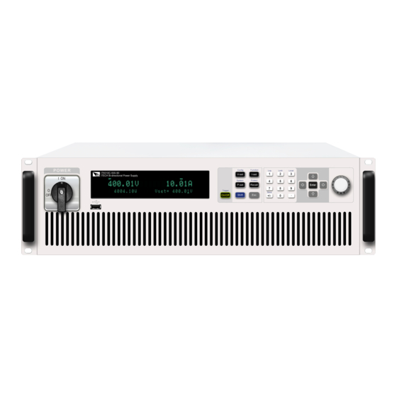
Bi-directional programmable dc power supply
Hide thumbs
Also See for IT6000C Series:
- User manual (161 pages) ,
- User manual (177 pages) ,
- User manual (251 pages)


Need help?
Do you have a question about the IT6000C Series and is the answer not in the manual?
Questions and answers