ITech IT6800A Series User Manual
Dc programmable power supply
Hide thumbs
Also See for IT6800A Series:
- Programming manual (53 pages) ,
- User manual (50 pages) ,
- Programming manual (53 pages)

Related Manuals for ITech IT6800A Series


Summary of Contents for ITech IT6800A Series
- Page 1 DC Programmable Power Supply User’s Manual IT6800A/B Series Model: IT6831A/IT6832A/IT6833A/IT6835A/IT6861A /IT6862A/IT6863A/IT6872A/IT6873A/IT6874A /IT6832B/IT6833B/IT6835B/IT6861B/IT6862B /IT6863B/IT6872B /IT6873B/IT6874B Version:3.1...
- Page 2 Notices Warranty Safety Notices © Itech Electronic, Co., Ltd. 2018 The materials contained in this No part of this manual may be document are provided “as is”, and reproduced in any form or by any means (including electronic storage and...
-
Page 3: Limitation Of Warranty
Warranty ITECH warrants that the product will be free from defects in material and workmanship under normal use for a period of one (1) year from the date of delivery (except those described in the Limitation of Warranty below). -
Page 4: Safety Precautions
Failure to comply with these precautions or specific warnings elsewhere in this manual will constitute a default under safety standards of design, manufacture and intended use of the instrument. ITECH assumes no liability for the customer’s failure to comply with these precautions. -
Page 5: Environmental Conditions
This affix product label indicates that you must not discard the electrical/electronic product in domestic household waste. Product Category With reference to the equipment classifications described in the Annex I of the WEEE Directive, this instrument is classified as a Copyright © Itech Electronic Co., Ltd. - Page 6 IT6800A/B User Manual “Monitoring and Control Instrument”. To return this unwanted instrument, contact your nearest ITECH office. Copyright © Itech Electronic Co., Ltd.
-
Page 7: Compliance Information
Connection of the instrument to a test object may produce radiations beyond the specified limit. Use high-performance shielded interface cable to ensure conformity with the EMC standards listed above. Safety Standard IEC 61010-1:2010/ EN 61010-1:2010 Copyright © Itech Electronic Co., Ltd. -
Page 8: Table Of Contents
5.1 Specifications ............................ 29 5.2 Supplementary Characteristics ......................40 Appendix ..............................41 Specifications of Red and Black Test Lines ..................... 41 No output ..............................41 How to avoid it couldn’t start when test battery ..................41 Copyright © Itech Electronic Co., Ltd. -
Page 9: Dc Programmable Power Supply
Please select appropriate space for installation based on the power supply size. series different models are the same size, the detail size IT6800A/B power supply of the are shown as below. (Take the example of IT6862A) power supply Copyright © Itech Electronic Co., Ltd. - Page 10 Inspection and Installation Dimension: Width: 255.3mm Height: 108.7mm Depth: 374.4mm Detailed Dimension Drawing Copyright © Itech Electronic Co., Ltd.
-
Page 11: Adjustment Of Handle
(Take the example of IT6862A) Horizontal placement Place the instrument on the desk horizontally. Adjustment Adjust the power supply handle to the state of rotation. Adjust the power supply handle to appropriate position. Copyright © Itech Electronic Co., Ltd. -
Page 12: Disassembly Of Handle
Align the locking mouth, and pull out the handle towards two sides. Rotate the handle to the appropriate position. NOTE Do not use too much force and mind your hands during disassembly of power supply handle Copyright © Itech Electronic Co., Ltd. -
Page 13: Rack Mounting
1.5 Rack Mounting This instrument can be installed on standard 19-inch rack. ITECH provides user with IT-E151/IT-E151A rack, as an optional mount kit. The detailed operation please refer to the User Manual of your mount kit. -
Page 14: Chapter2 Quick Start
IT6862B 0~32V/ 0~12V 0~3A/ 0~6A 0~96W/ 0~72W IT6863B 0~72V/ 0~32V 0~1.5A/ 0~3A 0~108W/ 0~96W IT6872B 0~35V/ 0~15V 0~4A/ 0~7A 0~140W/ 0~105W IT6873B 0~75V/ 0~32V 0~2A/ 0~4A 0~150W/ 0~128W IT6874B 0~150V/ 0~60V 0~1.2A/ 0~2A 0~180W/ 0~120W Copyright © Itech Electronic Co., Ltd. -
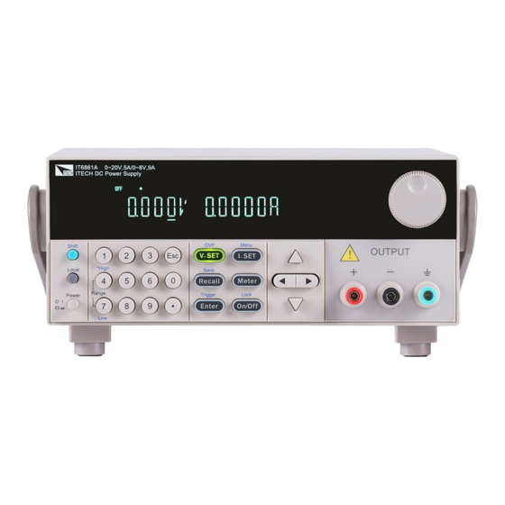
Page 15: Front Panel Introduction
⑥UP、DOWN, LEFT and RIGHT key, to move cursor ⑦Output terminals 2.3 Keypad introduction The key functions and keys of IT6830A/B series power supply are shown as below picture. The key functions and keys of IT6870A/B series power supply are shown as Copyright © Itech Electronic Co., Ltd. -
Page 16: Vfd Description
Up and down keys, used to select an item in the menu or increase (decrease) the output voltage or current values Escape key 2.4 VFD Description char char Function Function Output on timer function is Output is off Timer enabled Copyright © Itech Electronic Co., Ltd. -
Page 17: Rear Panel Introduction
Lock Keypad is locked 2.5 Rear Panel Introduction The rear panels of IT6800A/B series power supply are divided into series-A and series-B. The rear panels and keyboards of IT6800A series power supply are shown as below. ① ② Cooling window Remote sense terminal ③... -
Page 18: Power-On Selftest
To avoid burning out, pay attention to marks of positive and negative polarities before wiring. Self-test steps Normal self-test procedures: Correctly connect the power cord. Press [Power] key to start up. VFD display information is as below. INIT…. SCAN SYSTEM Copyright © Itech Electronic Co., Ltd. - Page 19 Check whether the fuse of electronic fuse is burned out. If yes, change fuse. Detailed steps: 1) Pull out power line and take out the fuse box at power line jack with a small screw driver. As shown below. Copyright © Itech Electronic Co., Ltd.
-
Page 20: Output Verification
Output verification verify that the power supply outputs the correct voltage and current levels and properly responds to entries from the front panel. Voltage Output Check The following steps verify basic voltage functions without load. Turn on the power supply Copyright © Itech Electronic Co., Ltd. - Page 21 0v, and the current on it is close to the value you set. Make sure that the current can be adjusted from 0 to full rated value. Turn off the output of the power supply, and remove the short wire. Copyright © Itech Electronic Co., Ltd.
-
Page 22: Chapter3 Functions And Characteristics
If you send the ‘OUTP ON’ command, the system will return the error message ‘Output Locked’. 3.3 Voltage setting IT6800A/B series power supply enables customer to set voltage from 0V to Copyright © Itech Electronic Co., Ltd. -
Page 23: Current Setting
CV mode. And CV status indicator lamp will be lit. If actual current is above the setting value or rated value, power supply will change to CC mode, and CC status indicator lamp will be lit. Copyright © Itech Electronic Co., Ltd. -
Page 24: Save/Recall
Press Esc button to return to the higher level menu and to quit the menu setting. IT6800A series Set the Maximum Voltage VOLT Reset Return to the factory default setup value P-MEM SYST “Remembers” and restores the operating (RESET) Keep Copyright © Itech Electronic Co., Ltd. - Page 25 Remote command trigger mode GRP1-8 Group set, used with Save/Recall operation (GROUP1) Disable timer function TIMER Enable timer function(0.1-9999.9S) Remain unchanged of previous menu setup RESET Return to factory default setup EXIT Quit system menu Copyright © Itech Electronic Co., Ltd.
- Page 26 Set the Power to OFF state after power up. “Remembers” and restores the power P-OUT ON/OFF state of power supply before (OFF) Keep power was turned off. The next time you power up the unit, the on/off state will be Copyright © Itech Electronic Co., Ltd.
- Page 27 Once you quit the SAVE list mode or turn off the unit, the file cannot be recalled. FILE0-FILE9 save list file to assigned memory Copyright © Itech Electronic Co., Ltd.
- Page 28 Power up setting (>P-MEM) P-MEM item is used to set operation parameters state of power supply after power up. If select RESET, means to initialize output parameters to factory default setup. Copyright © Itech Electronic Co., Ltd.
- Page 29 If select BUS, then sending command *TRIG can generate a trigger signal. Factory default set is MANU. Group set (MEM GROUP) IT6800A/B series power supply enables customer to store up to 9*8 groups of different operating parameters in a non-volatile memory for quick recall. Copyright © Itech Electronic Co., Ltd.
- Page 30 Once finished, the instrument will pause until the next trigger signal is received. Operation: Generate file:five steps: I-set I-set Press (Shift) + (Menu) into menu operation Enter VFD displays MAX VOLT, press to select LIST SET, press Copyright © Itech Electronic Co., Ltd.
- Page 31 Then the same operation as step 16) I-set I-set 18. Press (Shift)+ (Menu) into menu setup------press to select Enter LIST SET, press to confirm-------VFD displays LIST STATE, press Enter Enter to confirm-------press to select LIST >OFF, confirm. Copyright © Itech Electronic Co., Ltd.
-
Page 32: Ovp Function
This will allow the supply to automatically compensate for the voltage drop in the load leads and improve regulation. Copyright © Itech Electronic Co., Ltd. - Page 33 Connect output wires from + and – on front panel to the load input terminals 说明 NOTE To ensure the system stability, please using twisted-pair cables to connect sensing terminals and loads input terminals. Copyright © Itech Electronic Co., Ltd.
-
Page 34: Chapter4 Remote Operation
Remote Operation Chapter4 Remote Operation IT6800A series power supply provides two standard communication interfaces: RS232, USB. IT6800B series power supply provides three standard communication interfaces: RS232, USB, GPIB. User can select anyone to communicate with the computer. 4.1 RS232 interface There is a COM port (DB9)connector at the rear of the power supply, when connect to computer, you need to connect a cable with COM port on both side;... -
Page 35: Usb Interface
Use a Cable with two USB port to connect the power and the computer. All power functions can be programmed via USB. The USB488 interface functions of the power supply described as below: interface is 488.2 USB488 interface Interface Receive REN_CONTROL, GO_TO_LOCAL, Copyright © Itech Electronic Co., Ltd. -
Page 36: Gpib Interface (Only For It6800B Series)
I-set I-set key to enter the system menu function, find the GPIB address ▼ ▼ Enter Enter setting by button, type the address, key to confirm. GPIB address is stored in nonvolatile memory line. Copyright © Itech Electronic Co., Ltd. -
Page 37: Chapter5 Specifications
50%-100% Freq=1K 75mV Voltage1 110V±10% AC Input Voltage3 220V±10% Frequency 47HZ-63HZ ≦0.02%+3mV Voltage Setup stability-8h (%of Output +Offset) ≦0.1%+2mA Current ≦0.02%+3mV Voltage Readback stability-8h (%of Output +Offset) ≦0.1%+2mA Current Fuse specification 6.3A(110V)/3.15A(220V) Remote Sense Compensation Voltage Copyright © Itech Electronic Co., Ltd. - Page 38 Normal mode Ripple&Noise (20HZ-20M) <6mArms <5mArms Current Common mode <1.5uArms <1.5uArms Current Transient response time ( Recover to 75mV) 50%-100% load 100us 100us <100ms <150ms rise 10%-90% voltage settling time <350ms <550ms fall 10%-90% Copyright © Itech Electronic Co., Ltd.
- Page 39 Voltage3 220V±10% AC Input Frequen 47HZ-63HZ ≦0.02%+3mV Voltage Setup stability-8h (%of Output +Offset) ≦0.1%+2mA Current ≦0.02%+3mV Readback stability-8h Voltage (%of Output +Offset) ≦0.1%+2mA Current Remote Sense Compensation Voltage Command Response 20mS ( Typical) Time Copyright © Itech Electronic Co., Ltd.
- Page 40 Rise time 10%-90% <90ms <90ms <90ms Fall time 90%-10% <150ms <200ms <250ms Sample Rate 10HZ/S 10HZ/S 10HZ/S Protection OTP;OVP OTP;OVP OTP;OVP Dimension(mm) 214.5mmW*88.2mmH*354.6mmD Weight 8.5Kg Model IT6872A Output 0-35V,4A Dual range output Ratings /0-15V,7A Copyright © Itech Electronic Co., Ltd.
- Page 41 Model Voltage H:0-75V L:0-32V Output Ratings Current H:0-2A L:0-4A ( 0 ° C~40 ° C) Power H:150W L:128W Load ≤0.01%+4mV Voltage regulation (%of ≤0.01%+2mA Current output+offset) ≤0.01%+4mV Voltage Line regulation (%of output+offset) ≤0.01%+2mA Current Copyright © Itech Electronic Co., Ltd.
- Page 42 Sample rate 10HZ/S Protection OTP;OVP Dimension 214.5mmW×88.2mmH×354.6mmD (mm) Weight 8.5Kg IT6874A Model Voltage H:0-150V L:0-60V Output Ratings Current H:0-1.2A L:0-2A ( 0 ° C~40 ° C) Power H:180W L:120W Load regulation ≤0.01%+4mV Voltage (%of Copyright © Itech Electronic Co., Ltd.
- Page 43 Voltage 100us (50%-100% load Recover to 75mV) response time Sample rate 10HZ/S Protection OTP;OVP Dimension 214.5mmW×88.2mmH×354.6mmD (mm) Weight 8.5Kg Model IT6832B IT6833B Voltage / Output Ratings 0-32V/0-6A 0-72V/0-3A Current ≦0.01%+5mV ≦0.01%+4mV Voltage Load regulation Copyright © Itech Electronic Co., Ltd.
- Page 44 ≤0.01%+5mV Load regulation Voltage (%of ≤0.1%+3mA Current Output+Offset) ≤0.02%+5mV Line regulation Voltage (%of Output+Offset) ≤0.1%+3mA Current Voltage Programming Resolution Current Voltage Readback resolution Current Programming ≤0.04%+8mV Voltage accuracy 12 month ≤0.1%+8mA Current (25℃± 5℃) Copyright © Itech Electronic Co., Ltd.
- Page 45 750VA apparent power Storage temperature -10℃~70℃ Protection OVP/OTP Interface GPIB/USB/RS232 Isolation ( output to 200V ground) Operation 0~40℃ Environment Dimension 214.5mmW*88.2mmH*354.6mmD (mm) Weight 7.2Kg Model IT6861B IT6862B IT6863B Output Dual range 0-20V,5A/0-8V,9A 0-32V,3A/0-12V,6A 0-72V,1.5A/0-32V,3A Copyright © Itech Electronic Co., Ltd.
- Page 46 Voltage Programming Resolution Current 0.1mA 0.1mA Voltage Readback resolution Current 0.1mA 0.1mA Programming ≤0.04%+8mV ≤0.04%+8mV Voltage accuracy 12 month ≤0.1%+5mA ≤0.1%+5mA Current (25℃± 5℃) Readback ≤0.04%+8mV ≤0.04%+8mV Voltage accuracy 12 month ≤0.1%+5mA ≤0.1%+5mA Current Copyright © Itech Electronic Co., Ltd.
- Page 47 Current 0.1mA Voltage 1mV(<100V) 10mV(≧100V) Readback resolution Current 0.1mA Programming ≤0.05%+20mV Voltage accuracy 12 month ≤0.1%+5mA Current (25℃± 5℃) Readback ≤0.05%+20mV Voltage accuracy 12 month ≤0.1%+5mA Current (25℃± 5℃) Ripple ≤5mVp-p/1.5mVrms Voltage (20Hz ~20MHz) Copyright © Itech Electronic Co., Ltd.
-
Page 48: Supplementary Characteristics
AC input level(A transfer switch is selectable on the rear panel) Option Opt.01: 220VAC ± 10%, 47 to 63 Hz Option Opt.02: 110 VAC ± 10%, 47 to 63 Hz Cooling type Intelligent fans Copyright © Itech Electronic Co., Ltd. -
Page 49: Appendix
Specifications of Red and Black Test Lines ITECH provides you with optional red and black test lines, which individual sales and you can select for test. For specifications of ITECH test lines and maximum current values, refer to the table below. - Page 50 Contact Us Thanks for purchasing ITECH products. In case of any doubts, please contact us as follows: 1. Refer to accompanying data disk and relevant manual. 2. Visit ITECH website: www.itechate.com. 3. Select the most convenient contact method for further information.
Need help?
Do you have a question about the IT6800A Series and is the answer not in the manual?
Questions and answers