ITech IT6900 Series User Manual
Programmable dc power supply
Hide thumbs
Also See for IT6900 Series:
- Programming manual (55 pages) ,
- Programming manual (57 pages) ,
- User manual (47 pages)

Related Manuals for ITech IT6900 Series


Summary of Contents for ITech IT6900 Series
- Page 1 Programmable DC Power Supply IT6900 Series User Manual Model: IT6922A/IT6932A/IT6933A/IT6942A/ IT6952A/IT6953A/IT6922B/IT6932B/ IT6933B/IT6942B/IT6952B/IT6953B Version: V5.8...
- Page 2 (including electronic storage and “Caution” signs indicate danger. It is extent of laws, ITECH is not committed retrieval or translation into a foreign required to pay attention to the contents to any explicit or implied guarantee for...
-
Page 3: Warranty Service
ITECH, and ITECH will be responsible for return freight. If the product is sent to ITECH for warranty service from other countries, the customer will be responsible for all the freight, duties and other taxes. Limitation of Warranty This Warranty will be rendered invalid in case of the following: ... -
Page 4: Safety Precautions
In case of failure to follow these precautions or specific warnings in other parts of the manual, violation against the safety standards related to the design, manufacture and purpose of the instrument will occur. If the user does not follow these precautions, ITECH will bear no responsibility arising there from. ... -
Page 5: Environmental Conditions
Do not block the air vent of the equipment. Environmental Conditions The IT6900 series power supply can only be used indoors or in low condensation areas. The following table shows general environmental requirements for this instrument. Environmental conditions... -
Page 6: Waste Electrical And Electronic Equipment (Weee) Directive
According to the equipment classification in Annex I of the WEEE directive, this instrument belongs to the “Monitoring” product. If you want to return the unnecessary instrument, please contact the nearest sales office of ITECH. Copyright ©ITECH Electronic Co., Ltd. -
Page 7: Compliance Information
2. Connection of the instrument to a test object may produce radiations beyond the specified limit. 3. Use high-performance shielded interface cable to ensure conformity with the EMC standards listed above. Safety Standard IEC 61010-1:2010+A1:2016 Copyright ©ITECH Electronic Co., Ltd. -
Page 8: Table Of Contents
3.13 Analog Control Interface ........................26 Chapter4 Remote Operation Mode ....................29 4.1 RS232 interface ..........................29 4.2 USB interface ............................ 31 4.3 GPIB interface (IT6900(G) series only) ..................... 31 4.4 RS485 interface ..........................31 Copyright ©ITECH Electronic Co., Ltd. - Page 9 IT6900 User Manual Chapter5 Technical Specification ...................... 33 5.1 Major Technical Parameters ......................33 5.2 Supplemental Characteristics ......................39 Appendix ..............................40 Specifications of Red and Black Test Lines ..................... 40 Copyright ©ITECH Electronic Co., Ltd.
-
Page 10: Chapter1 Inspection And Installation
After confirming that package contents are consistent and correct, please appropriately keep package box and related contents. The package requirements should be met when the instrument is returned to factory for repair. IT6900 series power supply is supplied with the following optional accessories (sold separately): Item... - Page 11 Inspection and Installation Please select appropriate space for installation based on the electronic load size. IT6900 series power supply different models are not the same size, the detail size of the power supply is shown as below. IT6922A/IT6932A/IT6942A/IT6922B/IT6932B/IT6942B Models Detailed Dimension Drawing...
- Page 12 Inspection and Installation IT6933A/IT6933B Models Detailed Dimension Drawing Copyright ©ITECH Electronic Co., Ltd.
- Page 13 Inspection and Installation IT6952A/IT6953A/IT6952B/IT6953B Models Detailed Dimension Drawing Copyright ©ITECH Electronic Co., Ltd.
-
Page 14: Rack Mounting
Inspection and Installation 1.3 Rack Mounting IT6900 series power supply can be mounted on a standard 19” rack. ITECH provides user with IT-E151A rack, an optional mount kit. 1.4 Connecting the Power Cord Connect power cord of standard accessories and ensure that the power is under normal power supply. -
Page 15: Chapter2 Quick Start
20V for the output voltage, the maximum output current 100W/20V = 5A, but when the output voltage is down to 10V, due to IT6922A maximum current is 5A, so in this case the maximum output current is 5A. IT6900 series power comes with a standard communication interface RS232/USB/RS485, both desktop and system-based features, can be designed and tested according to your needs and provide multi-purpose solutions. -
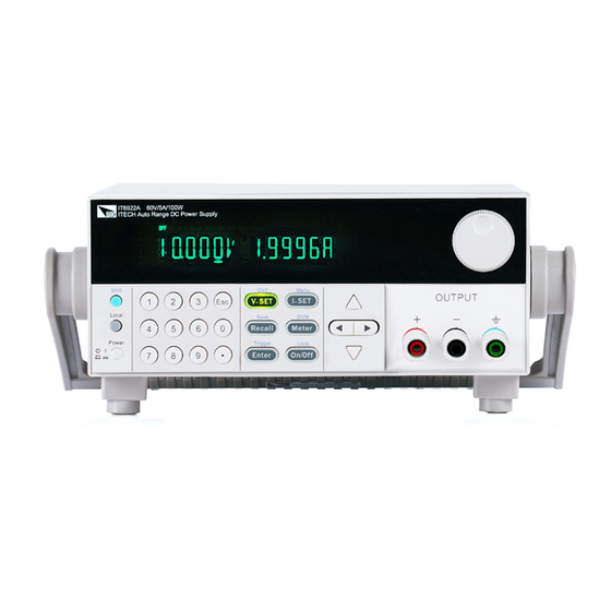
Page 16: Introduction To Front Panel
*IT6900(G) is the model with built-in GPIB, the function is the same as standard model, please check with ITECH for availability. 2.2 Introduction to Front Panel The front panel of IT6900 series is shown in the next figure. VFD display Rotary knob... -
Page 17: Key Introduction
Left and right movement keys, used to set the value, to adjust the cursor to the specified location. Up and down keys, used to select a item in the menu or increase (decrease) the output voltage or current values. Cancel /return keys. 2.4 VFD Description Copyright ©ITECH Electronic Co., Ltd. -
Page 18: Introduction To Rear Panel
The rear panel of IT6922A/IT6932A/IT6933A/IT6942A is shown in the next figure. Cooling window RS232 Communication cable interface USB Communication cable interface GPIB Communication cable interface (IT6900(G) series only) DVM input terminal, Remote measurement terminal and the output terminal AC power socket (fuse contained) Copyright ©ITECH Electronic Co., Ltd. - Page 19 USB Communication cable interface GPIB Communication cable interface (IT6900(G) series only) AC power socket (fuse contained) Output Sync signal interface and RS485 Communication cable interface DVM input terminal, Remote measurement terminal and the output terminal Copyright ©ITECH Electronic Co., Ltd.
-
Page 20: Power-On Self-Test
Do not use terminal board without protective grounding. Before operation, be sure that the power supply is well grounded. To avoid burning out, pay attention to marks of positive and negative polarities before wiring. Copyright ©ITECH Electronic Co., Ltd. - Page 21 3. Check whether the fuse of power supply is burned out. If yes, change fuse. Detailed steps: 1) Pull out power line and take out the fuse box at power line jack with a small screw driver. As shown below. Copyright ©ITECH Electronic Co., Ltd.
- Page 22 T6.3A 250V IT6952B T15A 250V T10A 250V IT6953B T15A 250V T10A 250V 3) After replacement, install the fuse box back to original position, as shown below. NOTE Fuse of IT6952A/IT6953A/IT6952B/IT6953B can unscrew directly by hand. Copyright ©ITECH Electronic Co., Ltd.
-
Page 23: Chapter3 Function And Features
This indicates that you can set current. There are three ways to set output current through front panel. I-set I-set The first way: press ,adjust cursor location through button, push will enable you to adjust the setting current value. Copyright ©ITECH Electronic Co., Ltd. -
Page 24: On/Off Operation
25V/10A, in fact, the unit can only output 25V/8A. 3.7 Saving Operation Customer can save some often-used parameters in nonvolatile memory. Recall can use the button (Save) button or SCPI order *SAV, *RCL to achieve this function. Saving parameters include: setting voltage/setting current Copyright ©ITECH Electronic Co., Ltd. -
Page 25: Trigger Operation
Set the power-on output state to be the last Keep power-off output state GPIB(IT6900(G) ADDR Address can be set within 0-30 series only) 4800 9600 19200 BAUD 38400 COMM (GPIB) 57600 RS232 115200 NONE 8BIT NONE 8BIT EVEN 8BIT ODD 8BIT MODE SIGNAL Copyright ©ITECH Electronic Co., Ltd. - Page 26 Do not save the current list file SAVE Save the list file to appointed FILE0-FILE9 document EXIT Quit the system menu POWER MODEL Unit model INFO The software version SN-1 The first six number of SN Copyright ©ITECH Electronic Co., Ltd.
- Page 27 0-30 COMM (GPIB) 4800 9600 19200 BAUD 38400 57600 115200 RS485 NONE 8BIT NONE 8BIT EVEN 8BIT ODD 8BIT SIGNAL MODE ADDR. Address can be set within 0-30 BEEP (ON) Close the key sound Copyright ©ITECH Electronic Co., Ltd.
- Page 28 Save the list file to appointed FILE0-FILE9 document EXIT Quit the system menu POWER MODEL Unit model INFO The software version SN-1 The first six number of SN SN-2 The middle six number of SN Copyright ©ITECH Electronic Co., Ltd.
- Page 29 This item can set the key sound state. If in on mode, then key sound will be there when you press buttons. If in off mode, the beeper will not make a sound. The default set is in on mode. Copyright ©ITECH Electronic Co., Ltd.
- Page 30 AD Speed Set (>ADC SPEED) This item is used to set the AD speed, i.e., measurement display speed of power supply. There are three kinds of AD speed, including SLOW, MID and FAST. Ex-factory set is in SLOW option. Copyright ©ITECH Electronic Co., Ltd.
- Page 31 >LIST EDIT, press to confirm Enter 4. VFD display >TIME SEC, press to confirm, go to the next step, you can also through button to select >TIME MIN time unit, press Enter to confirm. Copyright ©ITECH Electronic Co., Ltd.
- Page 32 Now you only need to press Enter (Trigger) to give a trigger signal, the list file can be ran. 18. In LIST mode, voltage set and current set button can’t be used, In LIST Copyright ©ITECH Electronic Co., Ltd.
-
Page 33: Ovp Function
STATE item, choose LIST>OFF will enable you to quit list mode. 3.10 OVP Function V-set V-set IT6900 series power supply provide OVP function, press button can enable you to set the over voltage protection value. Over voltage may caused by internal defect or customer’s incorrect operation(such as output voltage rising),or external voltage too high. - Page 34 Function and Features Digital Volt Meter (DVM) IT6900 series power supply has four semi-digital voltmeter. This DVM can Meter Meter measure 0.001V to 61.000V voltage. Press (DVM) button can enable the measured value display on the VFD screen. Press any key to quit the display of this value.
-
Page 35: Rs485 And Output Sync Signal Interface
External analog signals to control or monitor the output of the power supply. Refer to the following diagram for the signal connections of the analog interface. Copyright ©ITECH Electronic Co., Ltd. - Page 36 Group1~7. Pin5 ON/OFF Output on/off control, input analog is 0V or 10V, when input 0V, power output state is OFF, when input 10V, power output state is ON. Pin6 Monitor the output voltage. Copyright ©ITECH Electronic Co., Ltd.
- Page 37 Take IT6942B as an example, when the voltage output from this terminal is 5V, the corresponding output current of IT6942B is 7.5A. Pin8 NULL This pin is null. Pin9 Common reference ground for input/output analog and input digital. Copyright ©ITECH Electronic Co., Ltd.
-
Page 38: Chapter4 Remote Operation Mode
(e.g. PC). Do not use blank Modem cable. If your computer is using a RS-232 interface with DB-25 connector, you need an adapter cable with a DB-25 connector at one end and the other side is a DB-9(not blank modem cable) Copyright ©ITECH Electronic Co., Ltd. - Page 39 8 data bits, no parity Mode: SIGNAL, MUX SIGNAL (Single connection mode) , the MUX (Multiple connection mode) ADDR: Local address (0 to 30 factory default setting is 0) Start Bit 8 Data Bits Parity=None Stop Bit Copyright ©ITECH Electronic Co., Ltd.
-
Page 40: Usb Interface
User can set the following parameters of the RS485 interface: Baud rate: 9600(4800/9600/19200/38400/57600/115200) Parity and data bit: NONE/8BIT, EVEN/8BIT, ODD/8BIT EVEN 8 data bits, have even parity 8 data bits have odd parity NONE 8 data bits, no parity Copyright ©ITECH Electronic Co., Ltd. - Page 41 RS485 can be controlled by one PC by using the commands specific for multi-unit connection. See “Programming Guide” section for details. The figure below is a schematic diagram of the connection of 4 machines. Connect PC Copyright ©ITECH Electronic Co., Ltd.
-
Page 42: Chapter5 Technical Specification
Read back resolution ≤0.03%+5mV ≤0.03%+5mV ≤0.03%+5mV voltage (within twelve months) (25°C±5°C) ≤0.1%+5mA ≤0.1%+10mA ≤0.1%+15mA current ±(%of output+offset) ≤5mVp-p ≤8mVp-p ≤15mVp-p voltage Ripple ≤5mArms ≤6mArms ≤8mArms (20Hz ~20MHz) current Sample rate 10HZ Dimension (mm) 214.5mmW×88.2mmH×354.6mmD Weight (net) 7.7Kg Copyright ©ITECH Electronic Co., Ltd. - Page 43 Rise time(Full-load) voltage 300ms Fall time(No-load) voltage Fall time(Full-load) voltage 150ms Transient Response Time 200us Remote Sense Compensation Command Response Time 10~600ms Difference-mode 50mV voltage(Vpp) Difference-mode current 20mA (Arms) Setup Temp.coefficient voltage 50 PPM/°C +30mV Copyright ©ITECH Electronic Co., Ltd.
- Page 44 ±(%of output+offset) Read back resolution ≤0.03%+5mV ≤0.03%+20mV voltage (within twelve months) (25°C±5°C) ≤0.1%+25mA ≤0.1%+25mA current ±(%of output+offset) ≤20mVp-p ≤50mVp-p voltage Ripple ≤15mArms ≤15mArms (20Hz ~20MHz) current Sample rate 10HZ Dimension (mm) 214.5mmW×88.2mmH×445mmD 15Kg Weight (net) Copyright ©ITECH Electronic Co., Ltd.
- Page 45 (20Hz ~20MHz) ≤5mArms ≤6mArms current Sample rate 10HZ Dimension (mm) 214.5mmW×88.2mmH×354.6mmD Weight (net) 7.7Kg Parameters IT6933B voltage 0~150V Rated values current 0~5A (0 °C~40 °C) Power 200W ≤0.01%+20mV Load regulation voltage ±(%of output+offset) ≤0.01%+6mA current Copyright ©ITECH Electronic Co., Ltd.
- Page 46 50ppm/℃+30mV voltage Temp.coefficient (0 °C~40 °C) Setup 50ppm/℃+30mA current Readback 50ppm/℃+30mA current Sample rate 10HZ/S Working temperature 0℃~40℃ Storage temperature -10℃~70℃ Insulation voltage of 240V the output to ground Dimension (mm) 214.5mmW×88.2mmH×354.6mmD Weight (net) 7.7Kg Copyright ©ITECH Electronic Co., Ltd.
- Page 47 445mmD Weight (net) 7.7Kg 15Kg Parameters IT6953B voltage 0~150V Rated values current 0~10A ( 0 °C~40 °C) power 600W ≤0.01%+25mV Load regulation voltage ≤0.5%+10mA ±(%of output+offset) current ≤0.01%+25mV voltage Line regulation ≤0.5%+10mA ±(%of output+offset) current Copyright ©ITECH Electronic Co., Ltd.
-
Page 48: Supplemental Characteristics
Maximum input power: Model Maximum input power Model Maximum input power IT6922A 350VA IT6942A 1000VA IT6932A 550VA IT6952A 2000VA IT6933A 550VA IT6953A 2000VA IT6922B 350VA IT6932B 550VA IT6942B 1000VA IT6952B 2000VA IT6953B 2000VA IT6933B 550VA Copyright ©ITECH Electronic Co., Ltd. -
Page 49: Appendix
Specifications of Red and Black Test Lines ITECH provides you with optional red and black test lines, which individual sales and you can select for test. For specifications of ITECH test lines and maximum current values, refer to the table below. - Page 50 Contact Us Thanks for purchasing ITECH products. In case of any doubts, please contact us as follows: 1. Visit ITECH website: www.itechate.com 2. Select the most convenient contact method, for further information.
Need help?
Do you have a question about the IT6900 Series and is the answer not in the manual?
Questions and answers