ITech IT6900 Series Programming Manual
Programmable dc power supply
Hide thumbs
Also See for IT6900 Series:
- User manual (50 pages) ,
- Programming manual (57 pages) ,
- User manual (47 pages)

Related Manuals for ITech IT6900 Series


Summary of Contents for ITech IT6900 Series
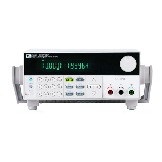
- Page 1 Programmable DC Power Supply Series IT6900 Programming Guide Model: IT6922A/IT6932A/IT6933A/IT6942A/ IT6952A/IT6953A/IT6922B/ IT6932B/IT6942B/IT6952B/IT6953B Version: V2.0...
- Page 2 Statement Guarantee Materials in the document are provided © Itech Electronics, Co., Ltd. 2016 No Safety Statement talis qualis and may be changed in part of this manual may be reproduced future revisions without prior notice. In in any form or by any means (including...
-
Page 3: Certification And Quality Assurance
ITECH, and ITECH will be responsible for return freight. If the product is sent to ITECH for warranty service from other countries, the customer will be responsible for all the freight, duties and other taxes. Limitation of Warranty This Warranty will be rendered invalid in case of the following: ... -
Page 4: Safety Precautions
In case of failure to follow these precautions or specific warnings in other parts of the manual, violation against the safety standards related to the design, manufacture and purpose of the instrument will occur. If the user does not follow these precautions, ITECH will bear no responsibility arising there from. ... -
Page 5: Environmental Conditions
IT6900 Programming Guide Do not block the air vent of the equipment. Environmental conditions The IT6900 series power supply can only be used indoors or in low condensation areas. The following table shows general environmental requirements for this instrument. Environmental conditions... -
Page 6: Waste Electrical And Electronic Equipment (Weee) Directive
According to the equipment classification in Annex I of the WEEE directive, this instrument belongs to the “Monitoring” product. If you want to return the unnecessary instrument, please contact the nearest sales office of ITECH. Copyright ©ITECH Electronics Co., Ltd. -
Page 7: Compliance Information
Connection of the instrument to a test object may produce radiations beyond the specified limit. Use high-performance shielded interface cable to ensure conformity with the EMC standards listed above. Safety Standard IEC 61010-1:2010/ EN 61010-1:2010 Copyright ©ITECH Electronics Co., Ltd. -
Page 8: Table Of Contents
STATus:QUEStionable:CONDition? ........................27 STATus:QUEStionable:ENABle <enabled value> ....................28 SYSTem:VERSion? ..............................28 SYSTem:ERRor? ..............................29 SYSTem:REMote ..............................29 SYSTem:LOCal..............................29 SYSTem:RWLock ..............................30 SYSTem:BEEPer ..............................30 SYSTem:COMMunicate:GPIB:RDEVice:ADDRess ....................30 SYSTem:INTerface ..............................31 Chapter4 Display Commands ......................... 32 Copyright ©ITECH Electronics Co., Ltd. - Page 9 MEASure:STATus? ..............................45 Chapter8 List Commands ..........................46 LIST:FUNCtion ..............................46 LIST:VOLTage ............................... 46 LIST:CURRent ..............................47 LIST:TIMEr ................................47 LIST:SAVE ................................48 LIST:LOAD ................................48 LIST:REPet ................................48 Chapter9 Calibration Commands ........................50 CALibration:SECure:[STATe] ..........................50 Copyright ©ITECH Electronics Co., Ltd.
- Page 10 IT6900 Programming Guide CALibration:INITital ............................. 50 CALibration:SAVe ..............................50 CALibration:VOLTage:LEVel ..........................51 CALibration:VOLTage [:DATA] {<numeric value>} ....................51 CALibration:CURRent:LEVel ..........................51 CALibration:CURRent [:DATA] {<numeric value>} ....................51 CALibration:STRing.............................. 52 CALibration:STRing? ............................52 CALibration:INITital ............................. 52 Copyright ©ITECH Electronics Co., Ltd. viii...
-
Page 11: Chapter1 Remote Control
Remote Control Chapter1 Remote Control 1.1 Overview This chapter will provide following remote configuration introductions: SCPI Command Introduction Command type Command format Data format Remote Operation 1.2 SCPI Command Introduction SCPI is short for Standard Commands for Programmable Instruments which defines a communication method of bus controller and instrument. - Page 12 Remote Control Multiple commands in a message Multiple SCPI commands can be combined and sent as a single message with one message terminator. There are two important considerations when sending several commands within a single message: Use a semicolon to separate commands within a message. ...
- Page 13 Remote Control within the voltage and current subsystems, and the use of the root specifier to move between subsystems. Including Common Commands You can combine common commands with subsystem commands in the same message. Treat the common command as a message unit by separating it with a semicolon (the message unit separator).
-
Page 14: Command Format
Remote Control 1.4 Command Format Formats for command display are as follows: [SOURce[1|2]:]VOLTage:UNIT {VPP|VRMS|DBM} [SOURce[1|2]:]FREQuency:CENTer {<frequency>|MINimum|MAXimum|DEFault} Based on the command syntax, most commands (and certain Parameter) are expressed in both upper and lower cases. Upper case refers to abbreviation of commands. - Page 15 Remote Control Semicolon (;) It is used to separate several commands in the same subsystem and can also minimize typing. For example, to send the following command string: TRIG:SOUR EXT; COUNT 10 has the same effect as sending the following two commands: TRIG:SOUR EXT TRIG:COUNT 10 Question mark (?)
-
Page 16: Data Type
Remote Control NOTE As for every SCPI message with one query sent to the instrument, the instrument will use a <NL> or newline sign (EOI) to terminate response of return. For example, if "DISP:TEXT?" is sent, <NL> will be placed after the returned data string to terminate response. -
Page 17: Scpi Status Register
Remote Control marks or double quotation marks are both allowed. Quotation mark separators may also act as one part of a string, they can be typed twice without any character added between them. String parameter is used in the following command: DISPlay:TEXT <quoted string>... - Page 18 Remote Control Questionable Status Enable Register Event Register VOLTAGE CURRENT Output Buffer not used not used TEMPERATURE not used not used not used not used OVERVOLTAGE OVERCURRENT Status Byte not used not used Enable Register Summary Register not used not used not used not used not used...
- Page 19 Remote Control which the standard event register records is: whether power output is turned on, order syntax errors, order execution errors, self-test or calibration errors, query errors and so on. Definition Operation Complete. All orders prior to and including an *OPC order have been executed.
-
Page 20: Remote Operation
The power supply is requesting service (serial poll). Not used Always set to 0. 1.7 Remote Operation IT6900 series power supply has three standard communication interface: RS232, USB, GPIB, the user can choose to any one of them to implement a communication with the computer. RS232 interface... - Page 21 Remote Control shows the plug pins. If your computer is using a RS-232 interface with DB-25 connector, you need a adapter cable with a DB-25 connector at one end and the other side is a DB-9(not blank modem cable) Base Description number No conjunction...
- Page 22 Remote Control USB interface Use a Cable with two USB port to connect the power and the computer. All power functions can be programmed via USB. The USB488 interface functions of the power supply described as below: Interface is 488.2 USB488 interface ...
-
Page 23: Chapter2 Ieee488.2 Commands
IEEE488.2 Commands Chapter2 IEEE488.2 Commands *CLS This order can clean the register as follows: Standard event status register Quest condition register Operation event register Status byte register Error code Order syntax: *CLS Parameter: None *ESE This order can set the parameter of standard event enable register. -
Page 24: Esr
4 segments divided by comma. Quest syntax: *IDN? Parameter: None Return parameter: <AARD> For example: ITECH Ltd,IT6922A,0123456789AF,1.00 *OPC When all orders before this order are executed, OPC is 1 for the standard event status register. Sending query order will return 1 to output buffer. -
Page 25: Psc
IEEE488.2 Commands Order syntax: *OPC Parameter: None Quest syntax: *OPC? Return parameter: <NR1> *PSC This order control if power supply send a query or not when it is reset. 1 OR ON:When power supply is reset, operation event enable register, query event enable register and standard event status register are all reset. -
Page 26: Sre
IEEE488.2 Commands Order syntax: *RST Parameter: None *SRE <enabled value> When query This order can set the parameter of standard event register. status bit enable register, the power will return a decimal number, this number is the binary weighted of enable register. Order syntax:... -
Page 27: Trg
IEEE488.2 Commands Quest syntax: *STB? Parameter: None Return parameter: <NR1> Reference order: *CLS *ESE *ESR *TRG When the trigger mode of the power supply is BUS order trigger mode, the Generates a trigger signal. The function is the same as order will TRIGger[:IMMediate] Order syntax:... -
Page 28: Rcl
IEEE488.2 Commands Example: *SAV 3 Reference order: *RCL *RCL This order can recall the parameter you saved before from the register. Order syntax: *RCL<NRf> Parameter: 1~72 Example: *RCL 3 Reference order: *SAV... -
Page 29: Chapter3 System Commands
System Commands Chapter3 System Commands STATus:QUEStionable[:EVENt]? This order can read the parameter from quest event register. the power supply will return a decimal number which is corresponding to the binary weighted sum of each bit of the register, these bits have been latched. After executing, quest event register is reset. -
Page 30: Status:questionable:enable
System Commands STATus:QUEStionable:ENABle <enabled value> This order can set the parameter of quest event enable register. The power binary-weighted sum supply will return a decimal number which is the of the enable register. Order syntax: STATus:QUEStionable:ENABle <NRf> Parameter: 0~255 Reset value: Consult *PSC order Example:... -
Page 31: System:error
System Commands SYSTem:ERRor? This order is used to query the error information of the power supply. When the error LED lights on the front panel, it tells us that there is one or more hardware or order syntax error happened. There are at most 20 groups of error message. Send the order once will read one error message from the error queue. -
Page 32: System:rwlock
System Commands RS232 interface. After execute this order, all the buttons on the front panel can be used. Order syntax: SYST:LOC Parameter: None Quest syntax: None SYSTem:RWLock This order is used to set the power supply to remote control mode through the RS232 interface, and LOCAL is not available too. -
Page 33: System:interface
System Commands Parameter: 0-30 Quest syntax: SYSTem:COMMunicate:GPIB:RDEVice:ADDRess? Returned parameter: <NR1> SYSTem:INTerface This order is used to switch the communication interface. Order syntax: SYSTem:INTerface <GPIB|USB|RS232>... -
Page 34: Chapter4 Display Commands
Display Commands Chapter4 Display Commands DISPlay This order is used to turn on/off the VFD display. When the display is off, the output and will not be displayed on the VFD, at the same time, all the LED except for ERROR led will not be off. When the control mode is local, the display will turn on automatically, press LOCAL button can switch the control mode from remote to local. - Page 35 Display Commands Order syntax: DISPlay[:WINDow]:TEXT:CLEar...
-
Page 36: Chapter5 Trigger Commands
Trigger Commands Chapter5 Trigger Commands TRIGger This order is used to generate a trigger signal when trigger source is in BUS mode. The function of this order is similar to *TRG. Order syntax: TRIGger[:IMMediate] Parameters: none Related orders: *TRG TRIG:SOUR TRIGger:SOURce This order is used to choose the source of trigger signal. -
Page 37: Chapter6 Output Commands
Output Commands Chapter6 Output Commands OUTPut This order is used to open or close the output of power supply. When output is off, the voltage and current of power supply is 0V/1mA. Order syntax: OUTP[:STATe] <bool> Parameters: 0|1|OFF|ON Query syntax: OUTPut? *RST value:... -
Page 38: Current {
Output Commands Unit: Query syntax: OUTPut:TIMer:DATA? Parameters: <NRf> CURRent {<current value>|MINimum|MAXimum|UP|DOWN|DEF} This order is used to set the output current. No matter what the current range you select currently, the output current is subject to the newest setting value. Besides, MIN and MAX can be used as parameters.MIN represents 0A,MAX represents the max value of the current range.|Minimum|Maximum|Up|Down|Def -
Page 39: Current:step
Output Commands Example: CURR:STEP 0.01 //set the stepping value to be 0.01A CURR UP //enable the output current increase value one time CURR:STEP 0.02 // set the stepping value to be 0.02A CURR DOWN // enable the output current decrease value one time CURRent:STEP This order is used to service for CURR UP and CURR DOWN two orders. -
Page 40: Voltage {
Output Commands Parameters: MIN to MAX Unit: Query syntax: CURRent:TRIG? [MINimum|MAXimum] Return parameters: <NR2> VOLTage {<volts>|MINimum|MAXimum|UP|DOWN|DEF} This order is used to set the output voltage. No matter what the voltage range you select currently, the output voltage is subject to the newest setting value. Besides, MIN and MAX can be used as parameters.MIN represents 0V,MAX represents the max value of the voltage range.|Minimum|Maximum|Up|Down|Def -
Page 41: Voltage:step {
Output Commands Return parameters: <NR2> Example: VOLT:STEP 0.01 //set the stepping value to be 0.01V VOLT UP //enable the output voltage increase one time VOLT:STEP 0.02 //set the stepping value to be0.02V VOLT DOWN //enable the output value decrease one time VOLTage:STEP {<value>|DEFault} This order is used to service for VOLT UP and VOLT DOWN two orders.|Default -
Page 42: Volt:protection {
Output Commands Order syntax: [SOURce:]VOLTage[:LEVel]:TRIGgered[:AMPLitude] <NRf> Parameters: MIN to MAX Unit: Query syntax: VOLT:TRIG? [MINimum|MAXimum] Return parameters: <NR2> VOLT:PROTection {<volts>|MINimum|MAXimum} This order is used to set the upper limit of over voltage protection point. If the output voltage value is higher than the upper limit of OVP, then we can assume that internal parts has been shorted.|Minimum|Maximum -
Page 43: Volt:protection:triped
Output Commands Order syntax: [SOURce:]VOLTage:PROTection:STATe Parameters: 0|1|OFF|ON Query syntax: VOLTage:PROTection:STATe? Return parameters: VOLT:PROTection:TRIPed? This order is used to inquire the execute state of OVP. If the return value is “1”,this represents that the OVP circuit has been triggered and the OVP state does not be cleared. -
Page 44: Apply {
Output Commands Parameters: MIN~MAX Unit: Query syntax: VOLTage:LIMIT? Return parameters: <NR2> APPLy {<voltage value>|DEF|MIN|MAX} [,{<current value>|DEF|MIN|MAX}] This order has combined two kinds of orders: VOLTage and CURRent. When sending this order to unit, power supply will output voltage and current according to the current setting of this order.|Def|Min|Max} [,{ |Def|Min|Max}] -
Page 45: Chapter7 Measurement Commands
Measurement Commands Chapter7 Measurement Commands MEASure:CURRent? This order is used to measure and return output current value. Order syntax: MEASure[:SCALar]:CURRent[:DC]? Return parameters: <NR2> FETCh:CURRent? This order is used to read the latest current to be processed from sampling buffer. When you send this order, then our unit will communicate with PC, and sending the current data to PC. -
Page 46: Measure:power
Measurement Commands Order syntax: FETCh[:VOLTage][:DC]? Return parameters: <NR2> MEASure:POWer? This order is used to measure the current output power value. Order syntax: MEASure[:SCALar]:POWer[:DC]? Return parameters: <NR2> FETCh:POWer? This order can read the latest power value from the sampling buffer. Order syntax: FETCh:POWer[:DC]? Return parameters:... -
Page 47: Measure:status
Measurement Commands Order syntax: FETCh:DVM[:DC]? Return parameters: <NR2> MEASure:STATus? This order is used to switch the display of VFD board between actual output state and DVM state. Order syntax: MEASure[:SCALar]:STATus <DVM|NORMAL>... -
Page 48: Chapter8 List Commands
List Commands Chapter8 List Commands LIST:FUNCtion This order is used to select the state of list mode. Order syntax: [SOURce:]LIST:FUNCtion<0|1> Query syntax: [SOURce:]LIST:FUNCtion? Return parameters: LIST:VOLTage This order is used to set the steps of list file and voltage of current step. Order syntax:... -
Page 49: List:current
List Commands LIST:CURRent This order is used to set the steps of list file and current value of current step. Order syntax: [SOURce:]LIST:CURRent <NRf> Parameters: MIN~MAX Unit: Example: LIST:CURR 1, 2A // set the first step‟s current to be 3A Query syntax:... -
Page 50: List:save
List Commands Query syntax: LIST:TIMEr? Example: LIST:TIME? 1 Return parameters: <NR2> LIST:SAVE This order is used to save the list file to specified memory region. Order syntax: [SOURce:]LIST:SAVE <NR1> Parameters: Example: LIST:SAVE 1 //save the edited list file to the first set of memory region. LIST:LOAD This order can recall the list file saved before from specified memory region. - Page 51 List Commands Order syntax: [SOURce:]LIST:REPet <NR1> Query syntax: LIST:REPet?
-
Page 52: Chapter9 Calibration Commands
Calibration Commands Chapter9 Calibration Commands CALibration:SECure:[STATe] Set protection mode enable or disable when calibrating the power supply. Order syntax: CALibration:SECure:[STATe] {<ON|OFF>,[<password>]} Parameters: 0|1|ON|OFF, „5811 Example: CAL:SEC 1, „5811; CAL:SEC OFF Query syntax: CALibration:SECure:STATe? Parameters: none CALibration:INITital This order is used to reset the calibration parameters to default setting. Order syntax:... -
Page 53: Calibration:voltage:level
Calibration Commands CALibration:VOLTage:LEVel This order can set voltage calibration point. P1、P2、P3、P4 must be calibrated orderly. Order syntax: CALibration:VOLTage:LEVel <point> Parameters: P1|P2|P3|P4 CALibration:VOLTage [:DATA] {<numeric value>} Return actual output voltage value of calibration point. Order syntax: CALibration:VOLTage [:DATA] <NRf> Parameters: <NRf> Example:... -
Page 54: Calibration:string
Calibration Commands Examples: CAL:VOLT 3.0002A CALibration:STRing Set the calibration information. Order syntax: CALibration:STRing <parameters> Parameters: The longest length is a string including 24 letters i.e related information the customer records during he running the calibration process, such as the calibration time and number of times and so on. Example:... - Page 55 Contact Us Thanks for purchasing ITECH products. In case of any doubts, please contact us as follows: 1. Refer to accompanying data disk and relevant manual. 2. Visit ITECH website:www.itechate.com 3. Select the most convenient contact method, for further information.
Need help?
Do you have a question about the IT6900 Series and is the answer not in the manual?
Questions and answers