ITech IT6000C Series User Manual
Bi-directional programmable dc power supply
Hide thumbs
Also See for IT6000C Series:
- User manual (161 pages) ,
- User manual (211 pages) ,
- User manual (251 pages)

Related Manuals for ITech IT6000C Series


Summary of Contents for ITech IT6000C Series
- Page 1 Via Acquanera, 29 22100 Como tel. 031.526.566 (r.a.) fax 031.507.984 info@calpower.it www.calpower.it Bi-directional Programmable DC Power Supply IT6000C Series User Manual Model: IT6000C Series Version: V1.1/04,2019...
- Page 2 CAUTION sign until the in- pose. ITECH shall not be held liable Manual Part Number dicated conditions are for errors or for incidental or indirect fully understood and met.
-
Page 3: Warranty
Warranty ITECH warrants that the product will be free from defects in material and work- manship under normal use for a period of one (1) year from the date of delivery (except those described in the Limitation of Warranty below). -
Page 4: Safety Symbols
Failure to comply with these precautions or specific warn- ings elsewhere in this manual will constitute a default under safety standards of design, manufacture and intended use of the instrument. ITECH assumes no li- ability for the customer’s failure to comply with these precautions. - Page 5 This instrument is used for industrial purposes, do not apply this product to IT power supply system. • Never use the instrument with a life-support system or any other equip- ment subject to safety requirements. Copyright © Itech Electronic Co., Ltd.
-
Page 6: Environmental Conditions
The instrument is designed for indoor use and an area with low condensation. The table below shows the general environmental requirements for the instrument. Environmental Conditions Requirements Operating temperature 0°C~40°C Operating humidity 20%~80%( non-condensation) Storage temperature -10°C~70 °C Copyright © Itech Electronic Co., Ltd. -
Page 7: Regulation Tag
The service life of the product is 10 years. The product can be used safely within the environmental protection period; otherwise, the product should be put into the recycling system. Copyright © Itech Electronic Co., Ltd. -
Page 8: Waste Electrical And Electronic Equipment (Weee) Directive
According to the equipment classifi- cation in Annex I of the WEEE direc- tive, this instrument belongs to the “Monitoring” product. If you want to return the unnecessary instrument, please contact the near- est sales office of ITECH. Copyright © Itech Electronic Co., Ltd. -
Page 9: Compliance Information
2. Connection of the instrument to a test object may produce radiations beyond the specified limit. 3. Use high-performance shielded interface cable to ensure conformity with the EMC standards listed above. Safety Standard IEC 61010-1:2010/ EN 61010-1:2010 Copyright © Itech Electronic Co., Ltd. -
Page 10: Table Of Contents
4.5.6 Over-Temperature Protection (OTP) ............55 4.5.7 Sense Reverse Protection................56 4.6 Function Menu for Power Supply................57 4.6.1 LIST Function ....................57 4.6.2 Battery Charging/Discharging Test Function..........62 4.6.3 Built-in Waveform Function ................. 65 Copyright © Itech Electronic Co., Ltd. VIII... - Page 11 6.1.6 IT6012C-800-40 ..................154 6.1.7 IT6018C-800-60 ..................156 6.1.8 IT6018C-2250-20 ..................158 6.2 Supplemental Characteristics................161 A Appendix ........................162 A.1 Specifications of Red and Black Test Lines............162 A.2 Fuse Replacement ....................163 Copyright © Itech Electronic Co., Ltd.
-
Page 12: Quick Reference
♦ Options Introduction 1.1 Brief Introduction The IT6000C series Bi-directional Programmable DC Power Supply supports a variety of output capabilities to satisfy different test requirement such as high current and low voltage or high voltage and low current. Meanwhile, units of the same model can be run in parallel to deliver stronger output capacity. - Page 13 • When the Sense function is turned on, it can ensure that the DUT is safe in case of reverse connection or open circuit of the Sense line. The models included in the IT6000C series are as follows: 500V 800V...
-
Page 14: Front-Panel Overview
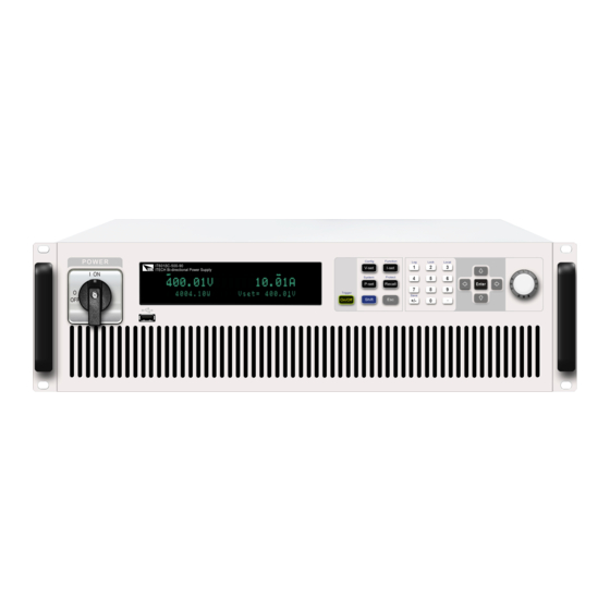
18,000W. 1.2 Front-Panel Overview For the IT6000C series Bi-directional Programmable DC Power Supply, all front panels of the 3U model are the same, and the operation panels of other models are the same as those of the 3U model. The following is the front panel sche- matic of the 3U model. -
Page 15: Keyboard Introduction
3 Function and composite keys 7 Vent hole 4 Numeric and composite keys 8 USB storage device connection port 1.3 Keyboard Introduction The keyboard introduction of IT6000C series Bi-directional Programmable DC Power Supply is shown as follows. Keys Description [On/Off] Turn the power supply output on or off. - Page 16 Up / Down The up and down navigation keys are used to scroll page up navigation and down to view menu items. keys [Enter] Operation confirmation key Copyright © Itech Electronic Co., Ltd.
-
Page 17: Push-On Knob
Save the common parameter settings. (Save) 1.4 Push-on Knob The IT6000C series Bi-directional Programmable DC Power Supply provides a knob on the front panel as shown in the next figure. The functions of the posh-on knob is described as follows. -
Page 18: Rear Panel Introduction
[Enter] key to confirm the operation. 1.5 Rear Panel Introduction The rear panel of the 3U model of the IT6000C series Bi-directional Program- mable DC Power Supply (after removing the protective cover) is shown below. 3U Models 1. - Page 19 The rear panel of the 6U model is the same as the 3U model. Other models (15U, 27U cabinets) have the same rear panel terminals except for the cabinet size. The following takes a 15U cabinet as an example. 1. Sense terminals (Vs+, Vs-) Copyright © Itech Electronic Co., Ltd.
-
Page 20: Vfd Indicator Lamps Description
10. AC power input terminals (L1, L2, L3, and PE) 11. Cabinet earthing rod 1.6 VFD Indicator Lamps Description The IT6000C series Bi-directional Programmable DC Power Supply VFD indica- tor lamps description is as follows: Table 1–1 VFD Indicator Lamps Description... -
Page 21: Configuration Menu Function
1.7 Configuration Menu Function This section gives an overview of the configuration menu of the IT6000C series power supply. The procedures to operate the configuration menu are as follows. 1. Press the composite keys [Shift]+[V-set] (Config) on the front panel to enter the configuration menu. -
Page 22: System Menu Function
1.8 System Menu Function This Chapter offers a general introduction of system menus, allowing users to have a preliminary understanding of system functions of this IT6000C series. The steps of the system menu function are as follows: 1. Press the composite keys [Shift]+[P-set] (System) on the front panel to en- ter the system menu. - Page 23 • Select the baud rate from the following options: 4800, 9600, 19200, 38400, 57600, 115200 • Select the data bit from the following op- tions: 5, 6, 7, 8 Copyright © Itech Electronic Co., Ltd.
- Page 24 Set the preferred address of the DNS server. If it is not involved, there is no need to set it. • DNS2: 0.0.0.0 Set the DNS server alter- nate address. If it is not Copyright © Itech Electronic Co., Ltd.
- Page 25 Select the baud rate from the following op- tions: 20k, 40k, 50k, 80k, 100k, 125k, 150k, Baudrate 200k, 250k, 400k, 500k, 1000k. Set the instrument address to a number Address from 1 to 65535. Copyright © Itech Electronic Co., Ltd.
- Page 26 External Analog Function. This function is optional. The menu can only Ext-Program display when corresponding board card is inserted. For details, see 5.12 Analogue Function (Ext-Program) (Optional). System Reset Select whether to restore the factory default settings or not. Copyright © Itech Electronic Co., Ltd.
-
Page 27: Options Introduction
System Info formation (System Info). 1.9 Options Introduction The IT6000C series Bi-directional Programmable DC Power Supply supports the following two types of accessories, the details are as below: • IT-E166: Interface card for GPIB communication. When users need to use GPIB communication, they can choose to purchase this accessory. - Page 28 You can use a multimeter to measure this pin. When the output voltage of the pin is in the range of 10±0.03%*10, it indicates that the accessory is functioning normally. Otherwise, the function is abnormal and cannot be used. Terminals for external analog function. . Copyright © Itech Electronic Co., Ltd.
-
Page 29: Inspection And Installation
Connecting the Power Cord. USB communication This accessory is se- cable lected when the USB in- terface is used for starting up remote operation. It contains User Manual, Programming Guide and other user documentations. Copyright © Itech Electronic Co., Ltd. -
Page 30: Instrument Size Introduction
2.2 Instrument Size Introduction The instrument should be installed at well-ventilated and rational-sized space. Please select appropriate space for installation based on the instrument size. The detailed dimension drawings of the IT6000C series are as follows: Copyright © Itech Electronic Co., Ltd. - Page 31 Inspection and Installation 3U Models 3U Slave Models Copyright © Itech Electronic Co., Ltd.
-
Page 32: Connecting The Power Cord
The disconnect device must be close to the equipment, be easily accessible, and be marked as the disconnect device for this equipment. Categories of Power Cords The standard power cord specifications for this series of 3U instruments are shown below: Copyright © Itech Electronic Co., Ltd. - Page 33 L1, L2 and L3 terminals one by one. b. The yellow-green wire is grounding wire, which is connected to the pro- tective grounding terminal (PE). Copyright © Itech Electronic Co., Ltd.
-
Page 34: Connecting The Device Under Test (Dut)
2.4 Connecting the Device Under Test (DUT) This section describes how to connect the test cables between the instrument and DUT. Precautions To prevent electric shock and damage to the instrument, observe the following precautions. Copyright © Itech Electronic Co., Ltd. - Page 35 • Always use test cables provided by ITECH to connect the equipment. If test cables from other factories are used, please confirm the maximum current that the test cables can withstand.
- Page 36 The connection diagram and steps of remote measurement are as follows: Copyright © Itech Electronic Co., Ltd.
- Page 37 Lethal voltages may remain at the out- put terminals after turn-off. Verify that there is no dangerous voltage on the output or sense terminals before touching them. Copyright © Itech Electronic Co., Ltd.
-
Page 38: Remote Interface Connection
• VCP: Virtual serial port. Select this type, you need to install the correspond- ing driver. Please contact ITECH Technical Support for the driver. • LAN: USB-LAN interface, which is a virtual network port. After selecting this option, you also need to set the communication parame- ters of the LAN, and the menu items are the same as those in the LAN menu. -
Page 39: Lan Interface
1. Press the composite keys [Shift]+[P-set] (System) on the front panel to en- ter the system menu. 2. Rotate the knob or press the Up/Down key to select I/O and press [Enter]. Copyright © Itech Electronic Co., Ltd. - Page 40 1.8 System Menu Function for details. Configure LAN Interface Information The configurable parameters of the IT6000C series power supply are described as follows. IP-Conf • IP Addr: This value is the Internet Protocol (IP) address of the instrument. An IP address is required for all IP and TCP/IP communications with the instru- ment.
- Page 41 5. Rotate the knob to select the service you want to enable and press [Enter]. 6. Rotate the knob to select whether to enable the service and press [Enter]. – On: Indicates that the service is enabled. – Off: Indicates that the service is disabled. Copyright © Itech Electronic Co., Ltd.
- Page 42 The detailed descriptions are as follows. • Home:Web home interface, displays the model and appearance of the instrument; • Information: Displays the serial number of the instrument and more system information as well as LAN configuration parameters; Copyright © Itech Electronic Co., Ltd.
-
Page 43: Can Interface
This page allows you to monitor and control the instrument; • LAN Configuration: Reconfigure the LAN parameters; • Manual: Go to the ITECH official website and view or download the relevant documents. • Upload: Performs a system upgrade. Click CONNECT to connect the PC with the instrument, then click Select File to select the system upgrade installation package (for example, itech_6000_P.itech), and then click UPLOAD performs the upgrade op-... - Page 44 The operation steps are as follows. 1. Press the composite keys [Shift]+[P-set] (System) on the front panel to en- ter the system menu. 2. Rotate the knob or press the Up/Down key to select I/O and press [Enter]. Copyright © Itech Electronic Co., Ltd.
-
Page 45: Gpib Interface (Optional)
5. Rotate the knob or press the Up/Down key to select I/O and press [Enter]. 6. Press the Left/Right key to select GPIB and press [Enter]. 7. Press the numeric keys to set the GPIB address and press [Enter]. Copyright © Itech Electronic Co., Ltd. -
Page 46: Interface (Optional)
3. Connect the instrument to the computer via an RS–232 cable. After the con- nection is successful, turn on the power switch of the instrument. 4. Press the composite keys [Shift]+[P-set] (System) on the front panel to en- ter the system menu. Copyright © Itech Electronic Co., Ltd. - Page 47 Make sure the correct cable and adapter are connected. Note that internal wiring may not be correct even if the cable has a suitable plug; • The cable must be connected to the correct serial ports (COM1, COM2, etc) of PC. Copyright © Itech Electronic Co., Ltd.
-
Page 48: Getting Started
When you turn the POWER switch on for the first time after purchase, the instru- ment starts with its factory default settings. Each time thereafter, the instrument starts according to the setting that you selected as outlined in 5.6 Set the Power-on State (PowerOn). Copyright © Itech Electronic Co., Ltd. - Page 49 Removing the power cord will disconnect AC input power to the unit. Power Switch Introduction User can adjust the power switch directly to turn on or turn off the instrument. The status of Power switch is as follows. Copyright © Itech Electronic Co., Ltd.
- Page 50 2. After the instrument is self-tested normally, the VFD shows the output volt- age, current, power and other information (CV mode). If an error occurs during the self-test, an error message is displayed. The follow- ing table lists the error messages you might see. Copyright © Itech Electronic Co., Ltd.
-
Page 51: Set Output Value
2.3 Connecting the Power Cord to select proper AC input. 4. If you need additional assistance, contact ITECH technical support engineer. 3.2 Set Output Value The voltage value, current value, power value can all be programmed. The user can set different output parameters within the range of specifications according to the need to satisfy a range of test requirement. -
Page 52: Use The Front Panel Menu
When the number in front of the menu item is blinking, indicates this item is selected currently. Press [Enter] key to enter the selected menu item and press [Esc] to exit the menu. Copyright © Itech Electronic Co., Ltd. -
Page 53: On/Off Control
DUT. If the power supply has no output after the output is turned on, check the voltage and current setting value, set the voltage and current to a non-zero value, and then turn on the output. Copyright © Itech Electronic Co., Ltd. -
Page 54: Power Supply Function
When [I-set] key is pressed, the key light is lit and the output current value can be set. Press numeric keys or rotate the knob to adjust the value in the current setting area indicated by the cursor. This value takes effect when you press [Enter]. Copyright © Itech Electronic Co., Ltd. -
Page 55: Set The Output Power
Do not use CV priority mode with low-impedance sources such as batteries, power supplies, or large charged capacitors. Copyright © Itech Electronic Co., Ltd. - Page 56 In CC priority mode, the output is controlled by a bi-polar constant current feed- back loop, which maintains the output source or sink current at its programmed setting. The output current remains at its programmed setting, provided the load Copyright © Itech Electronic Co., Ltd.
- Page 57 This can happen when the instru- ment is connected to an external device such as a battery, and its output voltage is higher than the voltage limit setting of the instrument. Once the Copyright © Itech Electronic Co., Ltd.
-
Page 58: Set The Internal Resistance
Vh, and press [V-set] again to set the voltage lower limit Vl. 4.4.2 Set the Internal Resistance The IT6000C series power supply provides internal resistance setting (CV prior- ity mode only). The procedures are shown as below. 1. Press the composite keys [Shift]+[V-set] (Config) on the front panel to enter the configuration menu. -
Page 59: Set The Output-On/Output-Off Delay
3. Set the output-on/output-off delay time and press [Enter] to confirm. 4.5 Protection Function for Power Supply The IT6000C series power supply provides the general protection functions such as overvoltage, overcurrent, overpower, undercurrent and undervoltage protection. The corresponding protection parameters can be configured in the Protect menu. - Page 60 Turn the UVP function off. (Def) Turn the UVP function on. Indicates the instrument warm-up time. This time is set to prevent the in- Warm-up strument from triggering protection when the voltage is rising. Be- cause this transient Copyright © Itech Electronic Co., Ltd.
- Page 61 The second row shows specific protection information, such as OVP. Clear the Protection After the instrument triggers protection and generates a protection message, you need to troubleshoot the possible cause. When the protection is resolved, Copyright © Itech Electronic Co., Ltd.
-
Page 62: Set Over-Voltage Protection (Ovp)
1. Press the composite keys [Shift]+[Recall] (Protect) on the front panel to en- ter the protection menu. 2. Press the up/down key or rotate the knob to select 1. OVP (Off) and press [Enter]. Copyright © Itech Electronic Co., Ltd. -
Page 63: Set Over-Current Protection (Ocp)
4. Set the protection limit Level and the delay time Delay in sequence, and press [Enter] to confirm. For bi-directional power supplies, Level can be set to a positive or nega- tive value, i.e. the same protection limit is set for the output or input current. Copyright © Itech Electronic Co., Ltd. -
Page 64: Set Over-Power Protection (Opp)
The VFD screen returns to the Protect menu and the OPP setting (take 150W, 1S as an example) is displayed as follows: PROTECT 3.OPP 150W, 1.000S Copyright © Itech Electronic Co., Ltd. -
Page 65: Set Under-Current Protection (Ucp)
0.1A, 1S as an example) is displayed as follows: PROTECT 4.UCP 10S, 0.1A, 1.000S 4.5.5 Set Under-Voltage Protection (UVP) Users can enable the UVP function and set the instrument warm-up time Warm-up, protection limit Level and protection delay time Delay. When the Copyright © Itech Electronic Co., Ltd. -
Page 66: Over-Temperature Protection (Otp)
Do not cover the ventilation holes on the rear panel, sides, or bottom of the instrument. Even with proper ventilation, the instrument can over- heat in the following situations. Copyright © Itech Electronic Co., Ltd. -
Page 67: Sense Reverse Protection
When you return power to the instrument, verify that the cooling fan is running. If not, please contact ITECH Technical Support. Leaving the instrument powered on with an inoperative cooling fan may result in damage to the instrument. -
Page 68: Function Menu For Power Supply
Function). 4.6.1 LIST Function The IT6000C series power supply supports a total of 10 List files (List01 to List10), each of which can be set up to 200 steps. You need to edit the voltage/ current value, slope and time width of each step, or you can set repeat times (1 to 65535) for each List file. - Page 69 List running. Trig Out Function switch that triggers the signal output. It is applicable to the scenario of synchronously controlling multiple units, that is, by connecting Copyright © Itech Electronic Co., Ltd.
- Page 70 If you choose not to save, press [Esc] to exit the editing interface. Import List Program If you need to run the List program on the external USB flash drive, you need to import the List program from the USB flash drive into the instrument. Copyright © Itech Electronic Co., Ltd.
- Page 71 5. Set the name of the List file to be recalled (that is, the file name set in Edit), and press [Enter]. The interface returns to the main interface of the LIST function, which is dis- played as follows: Copyright © Itech Electronic Co., Ltd.
- Page 72 3. Press the Left/Right key to select Open and press [Enter]. 4. Press the Left/Right key to select Internal and press [Enter]. 5. Set the name of the List file to be recalled (that is, the file name set in Edit), and press [Enter]. Copyright © Itech Electronic Co., Ltd.
-
Page 73: Battery Charging/Discharging Test Function
4.6.2 Battery Charging/Discharging Test Function The IT6000C series power supply provides the battery charging/discharging test function based on its unique bipolar power supply properties. Suitable for charg- ing/discharging tests on all types of portable batteries. - Page 74 Charge / or discharging Discharge time according to Time the selected test mode. Cut Off Voltage Battery test cut-off voltage Battery test cut-off current Cut Off Current Cut Off Capacity Battery test cut-off capacity Copyright © Itech Electronic Co., Ltd.
- Page 75 Sense cables, the VFD will display a negative voltage value, and you can- not turn on the output at this time. It can only be turned on after the cables are properly connected. 8. Based on the selected trigger method, perform the trigger operation. Copyright © Itech Electronic Co., Ltd.
-
Page 76: Built-In Waveform Function
4.6.3 Built-in Waveform Function The IT6000C series power supply supports built-in waveforms for user to exe- cute the test directly. The protocols/standards involved in the built-in waveforms include the following: •... - Page 77 4.6.3.1 Automotive Starting Waveform The IT6000C series power supply has built-in 12V or 24V DIN40839 waveform. This test verifies the behavior of a DUT during and after cranking. This wave- form can reproduce the voltage curve for automotive power network confirms to DIN40839 standard, thus facilitating quick call by customers.
- Page 78 24V. The user customizes the starting voltage of User-defined the automotive starting waveform. User-de- fined volt- V=8.00V age value DIN40839 for 12V System Steps Voltage (V) Current(A) Width(mS) Slope(mS) 2000 Copyright © Itech Electronic Co., Ltd.
- Page 79 8V-16V, the waveform is consistent with standard 12V; when the waveform program is divided into 16V-32V, the wave- form is consistent with the standard 24V waveform. The waveform diagram is shown below. Copyright © Itech Electronic Co., Ltd.
- Page 80 6. Press [On/Off] on the front panel to turn on the output. 7. According to the selected trigger method (same as the trigger method of the LIST function), for example, press [Shift]+[On/Off](Trigger) to trigger the output of the waveform. Copyright © Itech Electronic Co., Ltd.
- Page 81 12V starting profile cor- responding to Level 2. Select the voltage/duration of 12V starting profile cor- responding to Level 3. Select the voltage/duration of 12V starting profile cor- responding to Level 4. Select the 24V test system. Copyright © Itech Electronic Co., Ltd.
- Page 82 Select the 24V voltage system Pulse width Peak voltage Test B Select centralized load dump suppression Select the 12V voltage system Pulse width Peak voltage Select the 24V voltage system Pulse width Peak voltage Clamping voltage Copyright © Itech Electronic Co., Ltd.
- Page 83 5. Press the Left/Right key to select 12V and press [Enter] to confirm. The interface returns to the main interface of the system and displays SHORT-DROP. 6. Press [On/Off] on the front panel to turn on the output. Copyright © Itech Electronic Co., Ltd.
- Page 84 6. Press [On/Off] on the front panel to turn on the output. 7. According to the selected trigger method (same as the trigger method of the LIST function), for example, press [Shift]+[On/Off](Trigger) to trigger the output of the waveform. Copyright © Itech Electronic Co., Ltd.
- Page 85 12V, follow the set standards as below: I, II, III, and IV defined in the above standard correspond to levels 1, 2, 3, and 4 in the setup menu. • Standards for 24V system: Copyright © Itech Electronic Co., Ltd.
- Page 86 • The pulse duration of load dump is mainly determined by the time constant and pulse amplitude of the excitation circuit. Copyright © Itech Electronic Co., Ltd.
- Page 87 The pulse shape and parameters for an alternator with centralized load dump suppression (Test B) are given in follow. Copyright © Itech Electronic Co., Ltd.
- Page 88 If not otherwise agreed, use the upper voltage level with the upper value for in- ternal resistance or use the lower voltage level with the lower value for internal resistance. The following general considerations of the dynamic behavior of alternators dur- ing load dump apply: Copyright © Itech Electronic Co., Ltd.
- Page 89 Supply Voltage of 42 V — Electrical loads A test wave completely conforming to International Standard ISO21848 is built inside the device, which can be used for the test of Electrical and electronic Copyright © Itech Electronic Co., Ltd.
- Page 90 42V electrical system, where the upper limit is the protection volt- age of throw load. After turning on [On/Off] and triggering the waveform output, the instrument will apply a test pulse to the DUT, as shown below: Copyright © Itech Electronic Co., Ltd.
- Page 91 (for example, device installed with one or several micro controllers) . After turning on [On/Off] and triggering the waveform output, the instrument will apply test pulse and detect the reset performance of the DUT, as shown in the figure below. Copyright © Itech Electronic Co., Ltd.
- Page 92 DUT simultaneously. • t: Time time (in ms) t1: 5ms • U: Voltage (in V) t2: 15ms • : 18V t3: 50ms • : 21V t4: 10000ms • : 42V t5: 100ms Copyright © Itech Electronic Co., Ltd.
- Page 93 Select the 24V voltage system For details, see Table 4–1 Parameter Description Test–5 Load dump waveform Select centralized load dump Test A unsuppression Select the 12V volt- age system Test pulse width Peak voltage Copyright © Itech Electronic Co., Ltd.
- Page 94 Test pulse width Peak voltage Clamping voltage Select the 24V volt- age system Test pulse width Peak voltage Clamping voltage Test–2B Transient from DC motors acting as generators after ignition switch OFF: Copyright © Itech Electronic Co., Ltd.
- Page 95 Power Supply Function Parameters ≤0.05Ω ≤0.05Ω 0.2–2s 0.2–2s 1ms±50% 1ms±50% 1ms±50% 1ms±50% 1ms±50% 1ms±50% Test–4 Starter motor engagement disturbance pulse. Copyright © Itech Electronic Co., Ltd.
- Page 96 LV124 LV124 waveform protocol E-02 Transient overvoltage test waveform E-04 Jump start test waveform E-05 Load dump test waveform E-07 Slow decrease and increase of the supply voltage test waveform Copyright © Itech Electronic Co., Ltd.
- Page 97 These overvoltages are simulated by means of this test. This test may be used for the electrical life test. The test pulse of E-02 Transient overvoltage is shown in the figure below: Copyright © Itech Electronic Co., Ltd.
- Page 98 Dumping of an electric load, in combination with a battery with reduced buffering ability, results in an energy-rich overvoltage pulse due to the generator charac- teristics. The test pulse of E-05 Load Dump is shown in the figure below: Copyright © Itech Electronic Co., Ltd.
- Page 99 The reset behavior is represented by a voltage variance and a time variance. Two different test sequences are required to simulate different switchoff times. A component must always undergo both sequences. Copyright © Itech Electronic Co., Ltd.
- Page 100 In order to cover both cases, two different test sequences are required. A component must al- ways undergo both sequences. • Cold Start Test Pulse • Warm Start Test Pulse Copyright © Itech Electronic Co., Ltd.
-
Page 101: Solar Photovoltaic Curve Simulation Function (Sas)
4.6.4 Solar Photovoltaic Curve Simulation Function (SAS) The IT6000C series power supply provides the maximum power point tracking (MPPT) mechanism built-in, and it is very important to test the efficiency of this MPPT. The PV array/module/cell is a device that converts from light energy to electric energy. - Page 102 This function cannot be used in the VFD screen. Filter Filter the input voltage of the instrument to reduce interference. The filtering speed is low speed. The filtering speed is medium speed. Copyright © Itech Electronic Co., Ltd.
- Page 103 5. Set the Voc, Imp and the other parameters, and press [Enter]. After the setting is completed, the system returns to the main interface of the SAS function, and the currently edited custom curve is to be run. The interface is displayed as follows: FUNCTION Copyright © Itech Electronic Co., Ltd.
- Page 104 5. Based on the selected trigger method, perform the trigger operation. The trigger method of the SAS function is consistent with the trigger method of the List function, that is, the List trigger source is also effec- tive for the SAS function. • User-defined Copyright © Itech Electronic Co., Ltd.
-
Page 105: Battery Simulation Function
4.6.5 Battery Simulation Function The IT6000C series power supply can simulate battery characteristics in practi- cal applications based on its unique bipolar properties and the variable output impedance. You can set battery-related parameters to simulate the charge and discharge characteristics of the battery to assist with other tests. - Page 106 Set the number of bat- Serial teries in series. Positive current limit val- ue, which simulates the maximum discharge cur- rent of the battery pack. Negative current limit value, which simulates the maximum charge Copyright © Itech Electronic Co., Ltd.
- Page 107 • Edit battery simulation curve file 1. Access the ITECH website to download a template for the battery simula- tion curve file (.csv format). Also you can contact ITECH Technical Support. Copyright © Itech Electronic Co., Ltd.
- Page 108 USB flash disc. 2. Insert the USB flash disc into the USB interface on the front panel of the instrument. 3. Press the composite keys [Shift]+[I-set] (Function) on the front panel to enter the function menu. Copyright © Itech Electronic Co., Ltd.
- Page 109 OVP function and set the OVP level to the full voltage value. See 4.5.1 Set Over-Voltage Protection (OVP) for details. • When the SOC drops (simulated discharge), the voltage will also drop. When the voltage reaches empty voltage (Empty Voltage), the voltage will continue to drop. Copyright © Itech Electronic Co., Ltd.
- Page 110 Function menu item will be dis- played, you can re-enter the Function menu for editing; if No is selected, it means that the current running will not be stopped, and the main interface of the system is displayed. Copyright © Itech Electronic Co., Ltd.
-
Page 111: Basic Operation
This function can prevent the power supply from the panel keys misoperation during usage. Press the composite keys [Shift]+[2] (Lock) to lock front panel keys and the lock symbol “*” is shown on the front panel display. All panel keys, Copyright © Itech Electronic Co., Ltd. -
Page 112: Save And Recall Operations
You can do the save and recall operations by the following two methods. • Press the composite keys [Shift]+[+/-] (Save) to save the parameters. Press the [Recall] key to recall the parameters. • SCPI commands: *SAV and *RCL Copyright © Itech Electronic Co., Ltd. -
Page 113: Save Operation
3. Press [Enter] to recall the parameters. 5.4 Data Logging Function The IT6000C series Bi-directional Programmable DC Power Supply supports the recording and saving of test data. This Chapter introduces how to use this function in details. - Page 114 2. Set the value of Sample Period and press [Enter]. 3. Set the value of Duration and press [Enter]. Copyright © Itech Electronic Co., Ltd.
- Page 115 Logging, indicating that the data is recorded. The recorded da- ta is saved in USB memory device in .csv format. The user can get access to these files for analysis based on needs. Copyright © Itech Electronic Co., Ltd.
-
Page 116: Set The Beeper Status (Beep)
• Parameter setting values in the Config menu. • The output state of the power supply, i.e., the [On/Off] key state. The procedures to set the menu item are as follows. Copyright © Itech Electronic Co., Ltd. - Page 117 I- rated current of the instrument Upper limit of power: P+, and Rated power value of lower limit of power: P- the instrument [On/Off] status Config Mode menu Speed High Copyright © Itech Electronic Co., Ltd.
-
Page 118: Sense Function (Sense)
This menu item is used to switch the power supply to local measurement or re- mote sensing. The IT6000C series power supply supports two connection methods: Local measurement and Remote sensing. The remote sensing is used for maximizing measurement accuracy. (Refer to 2.4 Connecting the Device Under Test... -
Page 119: Select Trigger Source (Trig Source)
Basic Operation 5.8 Select Trigger Source (Trig Source) For the IT6000C series power supply, the List and data logging functions can be triggered for running by the following methods: • Manual: Default value, indicates the trigger occurs when the [Shift]+[On/Off] (Trigger) keys are pressed from the front panel. -
Page 120: Set Parallel Operation Mode (Parallel)
The IT6000C series power supply supports multiple instruments to work in par- allel mode to provide more power and current output capability. - Page 121 1. Ensure that the power switches of the three units and the main switch of the AC power distribution box are off. 2. Refer Figure 5–1 Wiring connection diagram to connect three units. Copyright © Itech Electronic Co., Ltd.
- Page 122 Configure the Menu Item. 5. After the parallel menu of the three units are set, restart the instrument separately. After the instrument is restarted, the VFD shows that the instrument is work- ing in parallel mode. Copyright © Itech Electronic Co., Ltd.
-
Page 123: Digital I/O Function (Digital Port)
5.11 Digital I/O Function (Digital Port) The IT6000C series power supply supports digital I/O function. The user can realize logic control over high and low level input or output by related configura- tions in the system menu, namely general digital signal I/O function. In addition to general digital I/O functions, this series can be customized to meet different special needs through different pin wirings. - Page 124 System→Digital Port→IO–2. Ps, signal Not-Invert menu item. For parameter introduction, see 5.11.2 IO–2. Ps, Not-Invert. Corresponds to the function set in the Level signal Level or PWM System→Digital Port→IO–3. Off- signal Status, Not-Invert menu item. For Copyright © Itech Electronic Co., Ltd.
- Page 125 (the seven pins each have a differ- ent custom function). The second and third options (Input and Output) are the general digital I/O function, and the parameter settings and functions of the sev- en pins are the same. Copyright © Itech Electronic Co., Ltd.
- Page 126 By default (i.e., the pin is not connected), it can be detected as high level, and the front panel will display input(0). If the pin is configured as Invert, it can be detected as low level, and the front panel will display input (1). Copyright © Itech Electronic Co., Ltd.
-
Page 127: Io-1. Ps-Clear, Not-Invert
When pin 1 is set to default Ps-Clear function, pin 1 has bi-directional I/O func- tion, which can receive pulse signal input from the external instrument and also can output pulse signal to external instrument. Pulse signal parameter require- ments are as follows: Copyright © Itech Electronic Co., Ltd. - Page 128 [On/Off] is from Off to On, pin 1 will send a pulse signal to the external instrument. 1. After confirming that the instrument’s OVP protection is cleared, man- ually turn on [On/Off]. 2. Check the oscilloscope and confirm whether pin 1 has pulse output. Copyright © Itech Electronic Co., Ltd.
-
Page 129: Io-2. Ps, Not-Invert
When pin 2 is set to default Ps function, pin 2 will output high or low level based on whether the instrument is under protection or not. Under normal conditions (Not under protection), and when pin 2 is under default setting (Not-Invert), pin Copyright © Itech Electronic Co., Ltd. -
Page 130: Io-3. Off-Status, Not-Invert
Not-Invert Not- Indicates whether to invert the input/output pulse Invert or level signal. • Invert: Yes Invert • Not-Invert: No Off- This default function indicates the exist- Status ing [On/Off] state of the instrument. Copyright © Itech Electronic Co., Ltd. - Page 131 [On/Off] is turned off, and pin 3 outputs high level; the[On/Off] is turned on, and pin 3 outputs low level. When pin 3 is set to Invert, the output level is completely opposite. 1. Refer to the figure below to connect pin 3 to the external oscilloscope. Copyright © Itech Electronic Co., Ltd.
-
Page 132: Io-4. Ext-Trig, Not-Invert
Trig–Out Indicates that when the instru- ment generates a signal (which triggers the Meter function, Da- ta Recording function and List function for running), pin 4 will output a pulse signal. Copyright © Itech Electronic Co., Ltd. - Page 133 False By default (Not-Invert), the out- put digital signal is 0 (i.e. high level), and in the case of Invert, the output is low level. Digital signal of PWM. PWM Freq Frequency Copyright © Itech Electronic Co., Ltd.
- Page 134 ListTrig Source is set to Manual. 5. Check the oscilloscope and confirm whether pin 4 has following pulse signal output. Level rise slope 10us Level fall slope Minimum time width 30us for low level keep • Trig-In Copyright © Itech Electronic Co., Ltd.
-
Page 135: Io-5. Inh-Living, Not-Invert
List file is running or not. 5.11.5 IO–5. INH-Living, Not-Invert Parameter Description IO–5. Living, Parameter setting for pin 5. Not-Invert Not- Indicates whether to invert the input/output pulse or Invert level signal. • Invert: Yes Invert • Not-Invert: No Copyright © Itech Electronic Co., Ltd. - Page 136 The [On/Off] button light is lighted on and VFD still displays On, but the actual output is 0; when pin 5 receives high level sig- nal again, the output state is recovered. Copyright © Itech Electronic Co., Ltd.
- Page 137 The pa- rameter requirements of this pulse signal are as follows: Level rise slope 10us Level fall slope Minimum time width 30us for low level keep Copyright © Itech Electronic Co., Ltd.
-
Page 138: Io-6. Sync-On, Not-Invert
When the protection state is cleared, manually turn on [On/Off] again. 5.11.6 IO–6. Sync-On, Not-Invert Parameter Description IO–6. Sync- Parameter setting for pin 6. On, Not- Invert Not- Indicates whether to invert the input/output pulse or Invert level signal. Copyright © Itech Electronic Co., Ltd. - Page 139 The parameter requirements of this pulse signal are as follows: Level rise slope 10us Level fall slope Minimum time width 30us for low level keep The bi-direction I/O functions are introduced as below: Copyright © Itech Electronic Co., Ltd.
-
Page 140: Io-7. Sync-Off, Not-Invert
B’s output function is synchronously turned on. 5.11.7 IO–7. Sync-Off, Not-Invert Parameter Description IO–7. Sync-Off, Parameter setting for pin 7. Not-Invert Not- Indicates whether to invert the input/output pulse Invert or level signal. Copyright © Itech Electronic Co., Ltd. - Page 141 The parameter requirements of this pulse signal are as follows: Level rise slope 10us Level fall slope Minimum time width 30us for low level keep The bi-direction I/O functions are introduced as below: Copyright © Itech Electronic Co., Ltd.
-
Page 142: Analogue Function (Ext-Program) (Optional)
The external analog function controls the actual output voltage/current value of the instrument by inputting a voltage between –10V and 10V to the specified pin, and limits the output of the voltage/current to a specified range. Copyright © Itech Electronic Co., Ltd. - Page 143 Ch2 and the input voltage of the corresponding pin, the voltage lower limit Vl will be adjusted according to the parameter setting of Ch3 and the input voltage of the corresponding pin. Copyright © Itech Electronic Co., Ltd.
- Page 144 Mx and Mb according to the following formulas, and then set the two values through the front panel keys or SCPI remote commands. The principle of parameter setting of Ch1 and Ch2 and Ch3 is the same, so the description will not be repeated. Copyright © Itech Electronic Co., Ltd.
- Page 145 CV priority • CC priority How to Use The following takes the CV priority mode as an example to introduce the usage steps. 1. Refer to the figure below to complete the pin connection. Copyright © Itech Electronic Co., Ltd.
- Page 146 4. Use knob or Up/Down key to select Ext-Program and press [Enter]. 5. According to step 2, set Mx and Mb of the corresponding pins. 6. Set the Ext-Program→On / Off to On to turn on the analog function. Copyright © Itech Electronic Co., Ltd.
-
Page 147: Restored To Factory Setting (System Reset)
Table 5–3 Initial value of the parameter Category Parameter Initial Value Voltage setting: Vs One percent of the rated Main voltage of the interface instrument Current setting: Is One percent of the rated current of the instrument Copyright © Itech Electronic Co., Ltd. - Page 148 • IP Addr: 192.168.0.1 • SubNet: 255.255.255.0 • Gateway: 192.168.0.1 • DNS1/DNS2: 0.0.0.0 • Socket Port: 30000 LAN→Serv-Conf MDNS/PING/Telnet- scpi/Web/VX-11/ Raw-socket: On • VCP: 9600,8,N,1 • (Optional) RS232: 9600,8,N,1 • (Optional) External analog: Off Copyright © Itech Electronic Co., Ltd.
-
Page 149: View The System Information (System Info)
UCP/UVP Protection point: Level OVP/OCP/OPP/UCP/UVP Delay time: Delay UCP/UVP Warm time: Warm-up 5.14 View the System Information (System Info) This menu item is used to view the system information of the instrument. Copyright © Itech Electronic Co., Ltd. -
Page 150: System Upgrade
Current Limit Display the maximum current limit. Run Time Display the power-on time. 5.15 System Upgrade The IT6000C series power supply supports the upgrade of the system version. System upgrade includes the following two methods: Copyright © Itech Electronic Co., Ltd. - Page 151 For example, when there are multiple system upgrading package post- fixed with .itech in the root directory of your USB flash drive, you need to use a text editing tool to open the configuration file and specify the up- grade package name corresponding to the present upgrade operation.
- Page 152 2. Power on the instrument. At this point, press Shift for several times till the instrument can detect the system upgrading files in the USB flash drive. After the system upgrading files are detected, the interface displays as follows: Copyright © Itech Electronic Co., Ltd.
- Page 153 The system will automatically perform upgrading. If No is selected, it means to exit upgrading, and the system will di- rectly enter into the main interface. 5. After the upgrading is completed, you need to restart the instrument manually. Copyright © Itech Electronic Co., Ltd.
-
Page 154: Technical Specification
This chapter will introduce the main technical parameters of thispower, such as rated voltage/current/power and so on. Besides, we will introduce the working environment and storage temperature. ♦ Main Specification ♦ Supplemental Characteristics 6.1 Main Specification Copyright © Itech Electronic Co., Ltd. -
Page 155: It6006C-500-30
±5℃) ±(%of Output+Offset) Power ≤0.5% + 0.5%FS Resistance ≤1% + 1%FS Ripple Voltage ≤200mVpp(MAX:≤500mVpp) (20Hz -20MHz) Current ≤0.1%FS RMS Setup Temperature Voltage ≤50PPM/℃ Coefficient (%of Output/℃+Offset) Current ≤200PPM/℃ Read Back Temperature Voltage ≤50PPM/℃ Coefficient Copyright © Itech Electronic Co., Ltd. - Page 156 Standard: USB, CAN, LAN; optional: GPIB, analog card, fiber Communication interface optic socket Isolation (output to ground) 1000V Working temperature 0 to 50℃ Number of series and ≤1 parallel units Dimension (mm) 483W*801.61D*151.3H Weight( net) 28KG Copyright © Itech Electronic Co., Ltd.
-
Page 157: It6012C-500-60
(within 12 months, 25℃ Current ≤0.1% + 0.1%FS ±5℃) ±(%of Output+Offset) Power ≤0.5% + 0.5%FS Resistance ≤1% + 1%FS Ripple Voltage ≤200mVpp(MAX:≤500mVpp) (20Hz -20MHz) Current ≤0.1%FS RMS Setup Temperature Voltage ≤50PPM/℃ Coefficient (%of Output/℃+Offset) Current ≤200PPM/℃ Copyright © Itech Electronic Co., Ltd. - Page 158 OVP, OCP, OPP, OTP and Vsense reversed protection Protective function Standard: USB, CAN, LAN; optional: GPIB, analog card, fiber Communication interface optic socket Isolation (output to ground) 1000V Number of series and ≤1 parallel units Working temperature 0 to 50℃ Copyright © Itech Electronic Co., Ltd.
-
Page 159: It6018C-500-90
Read Back Accuracy Voltage ≤0.02% + 0.02%FS (within 12 months, 25℃ Current ≤0.1% + 0.1%FS ±5℃) ±(%of Output+Offset) Power ≤0.5% + 0.5%FS Resistance ≤1% + 1%FS Ripple Voltage ≤200mVpp(MAX:500mVpp) (20Hz -20MHz) Current ≤0.1%FS RMS Copyright © Itech Electronic Co., Ltd. - Page 160 19.8kVA Storage temperature -10℃ to 70℃ OVP, OCP, OPP, OTP and Vsense reversed protection Protective function Standard: USB, CAN, LAN; optional: GPIB, analog card, fiber Communication interface optic socket Isolation (output to ground) 1000V Copyright © Itech Electronic Co., Ltd.
-
Page 161: It6018C-1500-30
Power ≤0.5% + 0.5%FS Resistance ≤1% + 1%FS Read Back Accuracy Voltage ≤0.02% + 0.02%FS (within 12 months, 25℃ Current ≤0.1% + 0.1%FS ±5℃) ±(%of Output+Offset) Power ≤0.5% + 0.5%FS Resistance ≤1% + 1%FS Copyright © Itech Electronic Co., Ltd. - Page 162 Maximum input current 33.37A Maximum input apparent 19.8kVA Storage temperature -10℃ to 70℃ OVP, OCP, OPP, OTP and Vsense reversed protection Protective function Standard: USB, CAN, LAN; optional: GPIB, analog card, fiber Communication interface optic socket Copyright © Itech Electronic Co., Ltd.
-
Page 163: It6006C-800-20
≤0.1% + 0.1%FS ±5℃) ±(%of Output+Offset) Power ≤0.5% + 0.5%FS Resistance ≤1% + 1%FS Read Back Accuracy Voltage ≤0.02% + 0.02%FS (within 12 months, 25℃ Current ≤0.1% + 0.1%FS ±5℃) ±(%of Output+Offset) Power ≤0.5% + 0.5%FS Copyright © Itech Electronic Co., Ltd. - Page 164 Remote Sense ≤8V (2Vmin) Compensation Command Response Time Power Factor 0.99 Maximum input current 19.27A Maximum input apparent 6.6kVA Storage temperature -10℃ to 70℃ OVP, OCP, OPP, OTP and Vsense reversed protection Protective function Copyright © Itech Electronic Co., Ltd.
-
Page 165: It6012C-800-40
Resistance 0.01mΩ Setup Accuracy Voltage ≤0.02% + 0.02%FS (within 12 months, 25℃ Current ≤0.1% + 0.1%FS ±5℃) ±(%of Output+Offset) Power ≤0.5% + 0.5%FS Resistance ≤1% + 1%FS Read Back Accuracy Voltage ≤0.02% + 0.02%FS Copyright © Itech Electronic Co., Ltd. - Page 166 Readback stability-8h Voltage ≤0.02% + 0.02%FS (%of Output +Offset) Current ≤0.1% + 0.1%FS Efficiency ~ 92% Remote Sense ≤8V (2Vmin) Compensation Command Response Time Power Factor 0.99 Maximum input current 22.25A Maximum input apparent 13.2kVA Copyright © Itech Electronic Co., Ltd.
-
Page 167: It6018C-800-60
Resistance 0.01mΩ Voltage 0.01V Current 0.001A Read Back Resolution Power 0.001kW Resistance 0.01mΩ Setup Accuracy Voltage ≤0.02% + 0.02%FS (within 12 months, 25℃ Current ≤0.1% + 0.1%FS ±5℃) ±(%of Output+Offset) Power ≤0.5% + 0.5%FS Copyright © Itech Electronic Co., Ltd. - Page 168 Voltage ≤0.02% + 0.02%FS (%of Output +Offset) Current ≤0.1% + 0.1%FS Readback stability-8h Voltage ≤0.02% + 0.02%FS (%of Output +Offset) Current ≤0.1% + 0.1%FS Efficiency ~ 92% Remote Sense ≤8V(2Vmin) Compensation Command Response Time Copyright © Itech Electronic Co., Ltd.
-
Page 169: It6018C-2250-20
Load regulation Voltage ≤0.02%FS ±(%of Output+Offset) Current ≤0.05%FS Voltage 0.1V Current 0.01A Setup Resolution Power 0.001kW Resistance 0.1mΩ Voltage 0.1V Current 0.01A Read Back Resolution Power 0.001kW Resistance 0.1mΩ Setup Accuracy Voltage ≤0.02% + 0.02%FS Copyright © Itech Electronic Co., Ltd. - Page 170 ≤0.1% +0.1%FS Readback stability-30min Voltage ≤0.02% + 0.02%FS (%of Output +Offset) Current ≤0.1% +0.1%FS Readback stability-8h Voltage ≤0.02% + 0.02%FS (%of Output +Offset) Current ≤0.1% +0.1%FS Efficiency ~ 92% Remote Sense ≤22.5V (2Vmin) Compensation Copyright © Itech Electronic Co., Ltd.
- Page 171 Standard: USB, CAN, LAN; optional: GPIB, analog card, fiber Communication interface optic socket Isolation (output to ground) 3000V Working temperature 0 to 50℃ Number of parallel units ≤8 483W*801.61D*151.3H Dimension (mm) 40KG Weight( net) Copyright © Itech Electronic Co., Ltd.
-
Page 172: Supplemental Characteristics
Technical Specification 6.2 Supplemental Characteristics State storage capacity: 10 sets Recommended calibration frequency: once a year Cooling style: fans Copyright © Itech Electronic Co., Ltd. -
Page 173: A Appendix
♦ Fuse Replacement A.1 Specifications of Red and Black Test Lines ITECH provides you with optional red and black test lines, which are sold indi- vidually and you can select for test. For specifications of ITECH test lines and maximum current values, refer to the table below. -
Page 174: Fuse Replacement
If there are no fuse assembly on the instrument rear panel, it means that you can’t replace the fuse by yourself. Please contact the ITECH engineer on the condition of the same malfunction. - Page 175 2. Have a visual inspection of the fuse to see whether it is burnt out; if yes, replace it with another fuse of the same specification. Re- fer to the corresponding technical specifi- cations for fuse rating. Copyright © Itech Electronic Co., Ltd.
- Page 176 3. Please replace with a fuse of the same specification. Refer to the technical specifi- cation of the corresponding instrument. 4. When install, put into the fuse box firstly. Then Push and turn the fuse box to 90 de- grees clockwise. Copyright © Itech Electronic Co., Ltd.
- Page 177 Contact Us Thanks for purchasing ITECH products. In case of any doubts, please con- tact us as follows: 1. Refer to accompanying data disk and relevant manual. 2. Visit ITECH website: www.itechate.com. 3. Select the most convenient contact method, for further information.
Need help?
Do you have a question about the IT6000C Series and is the answer not in the manual?
Questions and answers