
Related Manuals for Festo YXC Series


Summary of Contents for Festo YXC Series
- Page 1 Handling system YXC... Description Mechanical installation 8044168 1506a [8044170]...
- Page 2 • Activities that may be carried out in any order. 1. Activities that should be carried out in the order stated. – General lists. è Result of an action/References to more detailed information. Festo – GDCP-YXC-EN – 1506a – Deutsch...
-
Page 3: Table Of Contents
..........Festo – GDCP-YXC-EN – 1506a – English... - Page 4 ..........Festo – GDCP-YXC-EN – 1506a – English...
- Page 5 ..............Festo – GDCP-YXC-EN – 1506a – English...
- Page 6 ............Festo – GDCP-YXC-EN – 1506a – English...
-
Page 7: Safety And Requirements For Product Use
• Determine order ID of the handling system (è product labelling on the Y-module). • Download data sheet and CAD model from the Festo Support Portal by specifying the order ID (è www.festo.com/sp). -
Page 8: Safety
– outside of an industrial environment – in an invalid mounting position – with load limits exceeded – without sufficient risk evaluation of the complete system – without a safety concept for the complete system Festo – GDCP-YXC-EN – 1506a – English... -
Page 9: Permitted Mounting Position
– national specifications • For correct and safe use, take the following into account: – all warnings and notes – all load limits of the product and the connected components (è 1.1 Technical data) Festo – GDCP-YXC-EN – 1506a – English... -
Page 10: Obligations Of The Operating Company
– the applicable regulations for accident prevention and occupational safety – the documentation and mode of operation of the product. 1.5.3 Range of application and certifications Standards and test values that the product complies with and fulfills (è 1.1 Technical data). Festo – GDCP-YXC-EN – 1506a – English... -
Page 11: Transport And Storage
• Use correct tools. • Parts of the transport-protection crate are large and heavy; do not let them fall onto the product. • Remove marked transport protection aids (è 2.4.1 Securing in the transport protection crate). Festo – GDCP-YXC-EN – 1506a – English... -
Page 12: Transport Locks
• Use appropriate lifting gear (traverse) for safe handling. • Take weight into account (è label on transport protection crate). • Take adequate safety precautions. • Assign sufficient number of people for mounting. • Adjust lifting speed. Festo – GDCP-YXC-EN – 1506a – English... - Page 13 • Loosen the nuts of the lifting eye bolts. • Turn the lifting eye bolts in the respective direction of load. • Tighten the nuts of the lifting eye bolts (tightening torque: M8 = 12 Nm; M12 = 24 Nm). Festo – GDCP-YXC-EN – 1506a – English...
- Page 14 To lift the handling system safely: • Use mounted transport component kit. For the single-axis system and the linear gantry with EGC80/120/185 and EGC-HD To lift the handling system safely: • Use mounted transport component kit. Festo – GDCP-YXC-EN – 1506a – English...
- Page 15 • Use the following transport component kit. Mounting bracket (4x) Screw (2x) Lifting eye bolt (4x) Cable guide (1x) Slot nut (8 … 16x) Slot nut (2x) Nut (4x) Stay (2x) Screw (8x) Screw (8 … 16x) Festo – GDCP-YXC-EN – 1506a – English...
- Page 16 Screw size and tightening EHMX-EGC- torque M4x10 M5x12 M8x16 M10x16 [Nm] For clamping the Y-width (By): • Fasten stays with the slot nuts to the mount ing brackets. Screw size and tightening EHMX-EGC- torque M5x8 [Nm] Festo – GDCP-YXC-EN – 1506a – English...
- Page 17 • Fasten the cable guide with the slot nuts. • Wrap cables and hoses around the cable guide and clamp them with cable ties. Screw size and tightening EHMX-EGC- torque M5x8 [Nm] Festo – GDCP-YXC-EN – 1506a – English...
-
Page 18: Securing During Transport And Mounting
Safety component group at the Z-module A Z-module with motor from Festo has a brake function. There are no moving parts to secure there. For the Z-module without motor from Festo: For the long-stroke Z-module (EMHZ-DGEA/EHMZ-EGC), the drive shaft is clamped through a safety component group. - Page 19 Transport and storage EHMZ-DGEA Safety component group Z-axis EHMZ-EGC Safety component group Z-axis Festo – GDCP-YXC-EN – 1506a – English...
-
Page 20: Overview
The motor is connected to both X-axes through a connecting shaft. The positions of the motor and en ergy chain are dependent on the order. The following components are located on the motor side: • Energy chain • Multi-pin plug for sensors (optional) Festo – GDCP-YXC-EN – 1506a – English... - Page 21 Connecting shaft X-axis Motor (optional) Adapter Y-module Multi-pin plug/sensors (optional) X-axis Energy chain Adapter Y-module Motor position left (EHMX-...-L) Motor (optional) X-axis Connecting shaft Adapter Y-module X-axis Energy chain Adapter Y-module Multi-pin plug/sensors (optional) Festo – GDCP-YXC-EN – 1506a – English...
- Page 22 Overview Motor position middle (EHMX-...-M) Connecting shaft with gear unit/motor Adapter Y-module X-axis Energy chain Adapter Y-module Multi-pin plug/sensors (optional) X-axis 1) Accompanying Festo – GDCP-YXC-EN – 1506a – English...
-
Page 23: Y-Module Ehmy (Including Motor)
Motor X-module Motor Y-module Right Right Middle Left Left Left The following components are located on the motor side: – Input and output of the energy chain – Multi-pin plug for sensors (optional) Festo – GDCP-YXC-EN – 1506a – English... - Page 24 Overview Y-module for single-axis system/linear gantry EHMY-LP Y-axis Motor left (optional) Adapter Z-module/attachment components Energy chain Y-module for planar surface gantry/three-dimensional gantry EHMY-RP Y-axis Motor right (optional) Adapter Z-module/attachment components Energy chain Festo – GDCP-YXC-EN – 1506a – English...
-
Page 25: Z-Module Ehmz (Including Motor)/Dhmz
Overview 3.2.3 Z-module EHMZ (including motor)/DHMZ The Z module consists of an electric or pneumatic drive. The Z-module moves customer-provided attachments along the Z-axis. Structure Adapter on Y-module Energy chain Z-axis Motor (optional) Festo – GDCP-YXC-EN – 1506a – English... - Page 26 Overview Depending on the order, a three-dimensional or linear gantry is equipped with the following Z-modules. DHMZ-DGSL EHMZ-EGSL EHMZ-EGC EHMZ-DGEA (motor position left) (Motor position right) Adapter on Y-module Z-axis Festo – GDCP-YXC-EN – 1506a – English...
-
Page 27: Handling Systems
The single-axis system moves a customer-provided attachment linearly. Structure The following figure shows an example for the fundamental structure of the single-axis system. Y-axis Adapter, attachment components Energy chain Mounting components Motor (optional) Festo – GDCP-YXC-EN – 1506a – English... -
Page 28: Linear Gantry Yxcl
The following figure shows an example for the fundamental structure of the linear gantry. Z-axis Motor Z (optional) Mounting components Motor Y (optional) Y-axis Energy chain Z Energy chain Y Adapter, attachment components Festo – GDCP-YXC-EN – 1506a – English... -
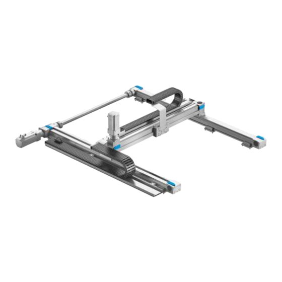
Page 29: Planar Surface Gantry Yxcf
The following figure shows an example for the fundamental structure of the planar surface gantry. X-axes Energy chain Y Energy chain X Y-axis Motor Y (optional) Adapter, attachment components Motor X (optional) Mounting components Connecting shaft 1) Dependent on order Festo – GDCP-YXC-EN – 1506a – English... -
Page 30: Three-Dimensional Gantry Yxcr
X-axes Connecting shaft Mounting components Energy chain Y Energy chain X Y-axis Motor Y (optional) Z-axis (electric/pneumatic) Motor Z (optional) Adapter, attachment components Motor X (optional) Energy chain Z 1) Dependent on order Festo – GDCP-YXC-EN – 1506a – English... -
Page 31: Handling Systems Without Motors
Overview Handling systems without motors • Use the following motors from Festo (recommended). X-module EHMX Axes Motor EGC-50-TB-KF EMMS-AS-40-M-LS-… EGC-80-TB-KF EMMS-AS-70-M-LS-… EGC-120-TB-KF EMMS-AS-100-M-HS-… EGC-185-TB-KF EMMS-AS-140-L-HS-… Y-module EHMY Axis Motor EGC-50-TB-KF EMMS-AS-40-M-LS-… EGC-80-TB-KF EMMS-AS-70-S-LS-… EGC-120-TB-KF EMMS-AS-100-S-HS-… EGC-125-TB-HD EMMS-AS-70-S-LS-… EGC-160-TB-HD EMMS-AS-100-S-HS-… EGC-185-TB-KF EMMS-AS-140-S-HS-…... -
Page 32: Installation Of The Single-Axis Systems And The Linear Gantries
2951 … 3550 – 3741 … 4370 3551 … 4150 – 4371 … 4500 4151 … 4500 1) Hy = stroke in Y-direction (è 1.1 Technical data) 2) n = number of mounting components Festo – GDCP-YXC-EN – 1506a – English... -
Page 33: Preparation Of The Mounting Surface
Depth of thread 9 9 13 1) Hy = stroke in Y-direction (è 1.1 Technical data) 2) n = number of mounting components (è 4.1.2 Number n of mounting components) Festo – GDCP-YXC-EN – 1506a – English... -
Page 34: Mounting Components
Mount product free of distortion. • • Use only the mounting kits supplied. Lock threaded connections. • • Make sure the mounting surface is sufficiently strong to absorb the maximum forces. Festo – GDCP-YXC-EN – 1506a – English... - Page 35 • Mount Y-module to a machine frame correspondingly. On the reverse side: 1. Unscrew screws on the support profile of the energy chain. Festo – GDCP-YXC-EN – 1506a – English...
- Page 36 7. Turn screw into the adjusting piece. 8. Place washer below the nut. 9. Screw nut onto the screw. 1) The accompanying screw and tightening torque are designed for mounting on steel. Festo – GDCP-YXC-EN – 1506a – English...
- Page 37 (Tightening torque 2.5 … 10 Nm) Check: – The screw has not twisted. – The alignment has been maintained. 13.Evenly tighten screws. Screw size and tightening EHMY-LP-EGC-...-KF EHMY-LP-EGC-...-HD torque M3x8 M5x16 M8x20 M5x16 M8x20 [Nm] Festo – GDCP-YXC-EN – 1506a – English...
- Page 38 On the reverse side: For mounting onto a machine frame: 15.Evenly tighten screw on the support profile of the energy chain. Screw size and tightening EHMY-LP-EGC-...-KF EHMY-LP-EGC-...-HD torque M5x8 M5x8 M5x12 M5x12 M5x10 M5x10 M5x10 [Nm] Festo – GDCP-YXC-EN – 1506a – English...
-
Page 39: Mounting Linear Gantry (Partially Mounted)
• Secure vertically or diagonally moving parts. Described is attachment of the Y-/Z modules to a linear gantry. • Pay attention to transport locks (è 2.4 Transport locks). Structure Linear gantry YXCL Y-module Z-module Festo – GDCP-YXC-EN – 1506a – English... -
Page 40: Mounting Of The Y-Module Ehmy-Lp
– Transport lock in the shipping crate is removed (è 2.4.1 Securing in the transport protection crate). – Transport lock for lifting is mounted (è 2.4.2 Securing when lifting ). – Function of the mounting components is known (è 4.2 Mounting components). Festo – GDCP-YXC-EN – 1506a – English... - Page 41 Installation of the single-axis systems and the linear gantries Mounting • Place Y-module slowly and carefully onto the prepared mounting surface. • Align Y-module (base module) horizontally and fasten it. Y-axis Screw set Mounting kit Adjusting piece Festo – GDCP-YXC-EN – 1506a – English...
-
Page 42: Mounting Of The Z-Module Ehmz/Dhmz
Installation of the single-axis systems and the linear gantries 4.3.2 Mounting of the Z-module EHMZ/DHMZ Structure DHMZ-DGSL EHMZ-EGSL EHMZ-EGC EHMZ-DGEA (motor position left) (Motor position right) Z-axis Adapter Y/Z Festo – GDCP-YXC-EN – 1506a – English... - Page 43 1. Place Z-module slowly and carefully onto the Y-module. 2. Press cylindrical dowel pins into the drill holes of the adapters. 3. Lock screws with adhesive. Observe safety instructions for adhesive in the manufacturer’s safety data sheet (è www.festo.com/en/msds). Festo – GDCP-YXC-EN – 1506a – English...
-
Page 44: Screw Size And Tightening Ehmy-Lp-Egc
Installation of the single-axis systems and the linear gantries 4. Fasten the adapter Z to the adapter Y with the screws. Screw size and tightening EHMY-LP-EGC-...-KF EHMY-LP-EGC-...-HD torque M4x10 M6x16 M8x14 M6x16 M8x14 [Nm] Festo – GDCP-YXC-EN – 1506a – English... -
Page 45: Installation Of Single-Axis System And Linear Gantry (Completely Mounted)
– Transport lock in the shipping crate is removed (è 2.4.1 Securing in the transport protection crate). – Transport lock for lifting is mounted (è 2.4.2 Securing when lifting ). – Function of the mounting components is known (è 4.2.1 Mounting kit with adjustment possibility). Festo – GDCP-YXC-EN – 1506a – English... - Page 46 Installation of the single-axis systems and the linear gantries Installation • Place handling system slowly and carefully onto the prepared mounting surface. • Align Y-module (base module) horizontally and fasten it. Y-axis Adjusting piece Screw set Festo – GDCP-YXC-EN – 1506a – English...
-
Page 47: Installation Of The Planar Surface Gantries And The Three-Dimensional Gantries
– 3851 … 4425 4351 … 4500 – 4426 … 4500 – 1) Hx = stroke in X-direction (è 1.1 Technical data) 2) n = total number of mounting components for both X-axes Festo – GDCP-YXC-EN – 1506a – English... -
Page 48: Preparation Of The Mounting Surface
The required flatness depends on the size of the handling system. Flatness [mm] 3 1000 1001 … 2000 2001 … 3000 3 1000 [mm] 1001 … 2000 0.2 2001 … 3000 0.3 3001 … 4000 0.4 4001 … 5000 0.5 Festo – GDCP-YXC-EN – 1506a – English... - Page 49 The drive shafts of the gear units and the hollow shafts must be sufficiently aligned (è 5.6.1 Mounting of the connecting shaft). EHMX-EGC-...-M Dimensions [mm] – 0.5 26.5 Depth of thread G2 14 Festo – GDCP-YXC-EN – 1506a – English...
- Page 50 1) By = width in Y-direction (è 1.1 Technical data) 2) Hx = stroke in X-direction (è 1.1 Technical data) 3) n = total number of mounting components for both X-axes (è 5.1.2 Number n of mounting components) Festo – GDCP-YXC-EN – 1506a – English...
- Page 51 The drive shafts of the gear units and the hollow shafts must be sufficiently aligned (è 5.6.1 Mounting of the connecting shaft). EHMX-EGC-...-M Dimensions [mm] 18.5 20.6 39.5 8 ± 3 8 ± 3 8 ± 3 Depth of thread G2 14 Festo – GDCP-YXC-EN – 1506a – English...
-
Page 52: Mounting Components
The mounting kits are pre-mounted to the X-axes. • Check number n and support spacing X2. • Place X-axes Partially mounted system è chapter 5.3 page 59 Completely mounted system è chapter 5.4 page 77. Festo – GDCP-YXC-EN – 1506a – English... - Page 53 Installation of the planar surface gantries and the three-dimensional gantries X-axis Mounting kit 1. Unscrew the screws of the upper part slightly. 2. Position mounting kit. Festo – GDCP-YXC-EN – 1506a – English...
- Page 54 M8x20 [Nm] 1) Accompanying screw and tightening torque are designed for mounting on steel. 5. Evenly tighten screws of the upper part. Screw size and tightening EHMX-EGC- torque M3x7 M5x16 M8x20 M8x20 [Nm] Festo – GDCP-YXC-EN – 1506a – English...
-
Page 55: Adjusting Kit
The adjusting kits are pre-mounted to the X-axes. • Check number n and support spacing X2. • Place X-axes. Partially mounted system è chapter 5.3 page 59 Completely mounted system è chapter 5.4 page 77. Festo – GDCP-YXC-EN – 1506a – English... - Page 56 Installation of the planar surface gantries and the three-dimensional gantries X-axis Adjusting kit 1. Slightly unscrew the screws on the underside. 2. Position adjusting plate. Festo – GDCP-YXC-EN – 1506a – English...
- Page 57 6. Lightly clamp the adjusting plate to the mount ing surface with the screws. 7. Use spanner with t 5 mm. If t 5 mm, the maximum height compensator is smaller by the difference (t − 5) mm. Festo – GDCP-YXC-EN – 1506a – English...
-
Page 58: Torque 1)
M5x30 M8x40 [Nm] 12 15 [mm] [mm] 7 ± 2 8 ± 3 Max. height compensator [mm] 1) Screw, tightening torque and screw-in depth are designed for mounting on steel. Festo – GDCP-YXC-EN – 1506a – English... - Page 59 • Bring vertically or diagonally moving parts into the lower end position in a controlled manner. • Secure vertically or diagonally moving parts. Described is mounting of the X-/Y-/Z-modules to a linear gantry or three-dimensional gantry. • Pay attention to transport protection (è 2.4 Transport locks). Festo – GDCP-YXC-EN – 1506a – English...
- Page 60 Installation of the planar surface gantries and the three-dimensional gantries Structure Planar surface gantry YXCF Three-dimensional gantry YXCR X-module Z-module Y-module Festo – GDCP-YXC-EN – 1506a – English...
-
Page 61: Mounting Of The X-Module Ehmx-Rp
Installation of the planar surface gantries and the three-dimensional gantries 5.3.1 Mounting of the X-module EHMX-RP Structure EHMX-...-L (Motor position left) EHMX-...-R (Motor position right) X-axis Connecting shaft X-axis with energy chain Festo – GDCP-YXC-EN – 1506a – English... - Page 62 Installation of the planar surface gantries and the three-dimensional gantries EHMX-...-M (Motor position middle) X-axis Connecting shaft with motor X-axis with energy chain Accompanying components Screw (12x) Centring sleeve (4x) Festo – GDCP-YXC-EN – 1506a – English...
- Page 63 Remove connector at the end of the respective motor cable. 2. Place X-axes slowly and carefully onto the prepared mounting surface. Check: – The guide rails lie inside. Guide rail 3. Lightly clamp X-axis with energy chain to the mounting surface. Festo – GDCP-YXC-EN – 1506a – English...
- Page 64 4. Align X-axis with energy chain to the underside. Check: straightness 0.1 mm × (Hx/1000) 5. Fasten X-axis with energy chain to the mounting surface. x = Hx/1000 y = By/1000 Festo – GDCP-YXC-EN – 1506a – English...
- Page 65 The height offset can be adjusted only with adjusting kits. For mounting kits without ad justment, the mounting surface must be correspondingly flat. 9. Fasten second X-axis to the mounting surface. Hollow shaft x = Hx/1000 y = By/1000 Festo – GDCP-YXC-EN – 1506a – English...
- Page 66 1) Calculation of the dimensions Y1 and X1, depending on the mounting component (è 5.1.3 Preparation of the mounting surface) The height offset can be adjusted only with adjusting kits. For mounting kits without ad justment, the mounting surface must be correspondingly flat. Festo – GDCP-YXC-EN – 1506a – English...
- Page 67 High wear and tension. • Align slides with each other. x = Hx/1000 y = By/1000 14.Fasten open coupling of the connecting shaft (è 5.6 Connecting shaft). 15.Mount Y-module (è 5.3.2 Mounting of the Y-module EHMY-RP). Festo – GDCP-YXC-EN – 1506a – English...
-
Page 68: Mounting Of The Y-Module Ehmy-Rp
(è 2.4.1 Securing in the transport protection crate ). – Transport lock for lifting is mounted (è 2.4.2 Securing when lifting ). – X-module is mounted (è 5.3.1 Mounting of the X-module EHMX-RP). Festo – GDCP-YXC-EN – 1506a – English... - Page 69 – Motor position of the Y-module is on the side of the energy chain on the X-module. X-module Y-module 4. Place centring sleeves (2x each) in the centring holes. 5. Fasten Y-module with the screws. Evenly tighten all screws (12x). Festo – GDCP-YXC-EN – 1506a – English...
- Page 70 Installation of the planar surface gantries and the three-dimensional gantries Screw size and tightening EHMX-EGC- torque M4x12 M5x12 M6x20 M8x20 [Nm] 6. Position Y-module in the middle on the X-module. X-module Y-module Festo – GDCP-YXC-EN – 1506a – English...
- Page 71 • Have the premounted bolt 1 fastened. Do not unscrew it. Fasten the adapter on one side: 7. Tighten screws evenly. Bolt (1x) Adapter (1x) Screw (6x ... 8x) Screw size and tightening EHMY-EGC- torque M3x8 M5x12 M6x16 M5x12 M6x16 [Nm] Festo – GDCP-YXC-EN – 1506a – English...
- Page 72 Installation of the planar surface gantries and the three-dimensional gantries 8. Move Y-module back and forth on the X-module one time. 9. Move Y-module into the middle. Festo – GDCP-YXC-EN – 1506a – English...
- Page 73 • Have the premounted bolt 1 fastened. Do not unscrew it. Fasten the adapter on the other side: 10.Tighten screws evenly. Bolt (1x) Adapter (1x) Screw (6x ... 8x) Screw size and tightening EHMY-EGC- torque M3x8 M5x12 M6x16 M5x12 M6x16 [Nm] Festo – GDCP-YXC-EN – 1506a – English...
-
Page 74: Mounting Of The Z-Module Ehmz/Dhmz
Installation of the planar surface gantries and the three-dimensional gantries 5.3.3 Mounting of the Z-module EHMZ/DHMZ Structure DHMZ-DGSL EHMZ-EGSL EHMZ-EGC EHMZ-DGEA (motor position left) (Motor position right) Z-axis Adapter Y/Z Festo – GDCP-YXC-EN – 1506a – English... - Page 75 1. Place Z-module slowly and carefully onto the Y-module. 2. Press cylindrical dowel pins into the drill holes of the adapters. 3. Lock screws with adhesive. Observe safety instructions for adhesive in the manufacturer’s safety data sheet (è www.festo.com/en/msds). Festo – GDCP-YXC-EN – 1506a – English...
-
Page 76: Screw Size And Tightening Ehmy-Lp-Egc
Installation of the planar surface gantries and the three-dimensional gantries 4. Fasten the adapter Z to the adapter Y with the screws. Screw size and tightening EHMY-LP-EGC-...-KF EHMY-LP-EGC-...-HD torque M4x10 M6x16 M8x14 M6x16 M8x14 [Nm] Festo – GDCP-YXC-EN – 1506a – English... - Page 77 Installation of the planar surface gantries and the three-dimensional gantries Installation of the planar surface gantries and the three-dimensional gantries (completely mounted) Structure Planar surface gantry YXCF Three-dimensional gantry YXCR X-module Z-module Y-module Festo – GDCP-YXC-EN – 1506a – English...
- Page 78 4. Fasten X-axis with energy chain to the mounting surface. 5. Align second X-axis flush with the mounted X-axis. – Length offset ± 0.4 mm × (By/1000) 6. Lightly clamp second X-axis to the mounting surface. Festo – GDCP-YXC-EN – 1506a – English...
- Page 79 1001 … 2000 0.2 2001 … 3000 0.3 3001 … 4000 0.4 4001 … 5000 0.5 1) Calculation of the dimensions Y1 and X1, depending on the mounting component (è 5.1.3 Preparation of the mounting surface) Festo – GDCP-YXC-EN – 1506a – English...
- Page 80 11.The slides of the X-module are blocked with motor position left/right. To be able to move the slides for alignment: – For motor with brake. Remove motor (è 5.7 Motor with brake (EMMS-...-RSB/RMB). – For motor without brake Remove connector at the end of the respective motor cable. Festo – GDCP-YXC-EN – 1506a – English...
- Page 81 Installation of the planar surface gantries and the three-dimensional gantries 12.Move Y-module back and forth on the X-module one time. 13.Move Y-module into the middle of the X-axes. Festo – GDCP-YXC-EN – 1506a – English...
- Page 82 Installation of the planar surface gantries and the three-dimensional gantries 14.Tighten screws evenly. Screw size and tightening EHMY-EGC- torque M3x8 M5x12 M6x16 M5x12 M6x16 [Nm] 15.Check mechanical alignment and structure (è 5.5 Check the alignment and structure). Festo – GDCP-YXC-EN – 1506a – English...
-
Page 83: Check The Alignment And Structure
Align handling system again, if necessary. For motor with brake: Mount motor (è 5.7 Motor with brake (EMMS-...-RSB/RMB)/(è 5.6 Connecting shaft). 3. Execute test run (è 8 Commissioning). Festo – GDCP-YXC-EN – 1506a – English... -
Page 84: Connecting Shaft
Installation of the planar surface gantries and the three-dimensional gantries Connecting shaft 5.6.1 Mounting of the connecting shaft Structure For motor position left/right Connecting tube (1x) Screw (2x) Screw (6x) Drive shaft (2x) Coupling (2x) Plug (2x) Festo – GDCP-YXC-EN – 1506a – English... - Page 85 (è 5.4 Installation of the planar surface gantries and the three-dimensional gantries (completely mounted)). – Y-module is mounted and aligned (è 5.3.2 Mounting of the Y-module EHMY-RP), (è 5.4 Installation of the planar surface gantries and the three-dimensional gantries (completely mounted)). – Hollow shafts are aligned. Festo – GDCP-YXC-EN – 1506a – English...
- Page 86 – Drive shafts on the gear unit Check connecting tube and couplings for excellent condition. Check: no kinks, dents, deflections. Insert a screwdriver into the cut-out. Lift off covers at the hollow shafts. Festo – GDCP-YXC-EN – 1506a – English...
- Page 87 – The hollow shafts no longer turn when the clamping screws are tightened. 5. Push the drive shaft with the expanding man drel as far as possible into the hollow shaft. 6. Tighten clamping screws. Screw size and tightening EHMX-EGC- torque [Nm] Festo – GDCP-YXC-EN – 1506a – English...
- Page 88 • Turn screw into the thread G1. • Push out expanding mandrel cone. Thread size EHMX-EGC- 7. Unscrew the screws. 8. Lift off half-shell. 9. Push couplings as far as possible onto the drive shafts. Festo – GDCP-YXC-EN – 1506a – English...
- Page 89 Installation of the planar surface gantries and the three-dimensional gantries Tighten screw slightly: è All couplings are fixed. Only for EHMX 185 • Push the plugs into the connecting tube. Festo – GDCP-YXC-EN – 1506a – English...
- Page 90 Installation of the planar surface gantries and the three-dimensional gantries For motor position left/right 1. Place connecting tube into the couplings. 2. Continue with point 8. (è page 92). Festo – GDCP-YXC-EN – 1506a – English...
- Page 91 4. Fasten gear unit to the mounting surface. 5. Push couplings as far as possible onto the drive shafts. 6. Tighten the screws lightly. Check: The couplings are fixed on both sides. Festo – GDCP-YXC-EN – 1506a – English...
- Page 92 7. Place connecting tubes into the coupling. 8. Unscrew the coupling screws slightly. 9. Align couplings in the middle. 10.Observe push-in depth B of the shaft. Push-in depth EHMX-EGC- 10.2 13.1 21.6 26 [mm] Festo – GDCP-YXC-EN – 1506a – English...
- Page 93 [Nm] 12.Place half shells. Tighten screws only lightly at first. 13.Clamp connecting tube to the half shell evenly and symmetrically. 14.Tighten screws. Screw size and tightening EHMX-EGC- torque M4x16 M5x18 M10x30 M12x40 [Nm] Festo – GDCP-YXC-EN – 1506a – English...
-
Page 94: Motor With Brake (Emms
• Push motor onto the X-axis. Check: correct position of the coupling hubs in relation to each other. • Connect motor flanges together. Tightening torques M4: 3 Nm M6: 10 Nm M8: 18 Nm Festo – GDCP-YXC-EN – 1506a – English... -
Page 95: Attachment Components
For linear gantry and three-dimensional gantry: • Mount attachment components to the Z-module. The corresponding interface is taken from the CAD model (è 1.1 Technical data). • Connect attachment components to the earth potential (è 7.2 Earthing). Festo – GDCP-YXC-EN – 1506a – English... -
Page 96: Installation
Start work on plug connectors and interfaces only when the residual voltage has fallen to a harmless level (è documentation of the controller used). • Switch the power supply back on only after completion of work. Festo – GDCP-YXC-EN – 1506a – English... - Page 97 Injury due to whipping. • Cut hoses off at right angles. • Push hoses into the fitting up to the stop. • Check hoses for tight fit. Festo – GDCP-YXC-EN – 1506a – English...
-
Page 98: Earthing
(è 7.3 Cables and hoses). 1. Emplace serrated washer. 2. Place cable lugs of the earthing cables between serrated washer and washer. 3. Tighten nut or bolt (tightening torque 4 Nm). Serrated washer Washer Festo – GDCP-YXC-EN – 1506a – English... -
Page 99: Earthing Points At The Single-Axis System
• Connect earthing point 2 of the Y-module with low impedance to earthing point 3 at the moment compensator. • Connect attachment components with low impedance to earthing point 3 at the moment com pensator. Festo – GDCP-YXC-EN – 1506a – English... -
Page 100: Earthing Points At The Linear Gantry
• Connect earthing point 2 of the Y-module with low impedance to earthing point 3 at the moment compensator. • Connect earthing point 3 at the moment compensator with low impedance to earthing point 4 of the Z-module • Connect attachment components with low impedance to earthing point 5. Festo – GDCP-YXC-EN – 1506a – English... -
Page 101: Earthing Points At The Planar Surface Gantry
• Connect attachment components with low impedance to earthing point 5 at the moment com pensator. 1) The earthing points 3 and 4 can be designed as one or two earthing points, depending on the order. Festo – GDCP-YXC-EN – 1506a – English... -
Page 102: Earthing Points At The Three-Dimensional Gantry
• Connect earthing point 5 at the moment compensator with low impedance to earthing point 6 of the Z-module. • Connect attachment component with low impedance to earthing point 7. 1) The earthing points 3 and 4 can be designed as one or two earthing points, depending on the order. Festo – GDCP-YXC-EN – 1506a – English... -
Page 103: Cables And Hoses
Multi-pin plug 1 -1X1 -2X1 -3X1 Multi-pin plug 2 -3X2 (optional) 7.3.2 Hoses Hoses must be uniquely identifiable. Hose colour Function Black Extend pneumatic drive Silver Retract pneumatic drive Blue For customer-specific applications Festo – GDCP-YXC-EN – 1506a – English... - Page 104 Installation Hose size Minimum ben DHMZ-DGSL- ding radius PUN-3x0,5 12 mm PUN-4x0,75 17 mm PUN-6x1 26.5 mm Festo – GDCP-YXC-EN – 1506a – English...
-
Page 105: Energy Chain Subdivision Z-Modules
Chambers for EHMZ-DGEA or EHMZ-EGSL For customer-specific allocation For customer-specific allocation Plug sockets with cable Earthing cable 1) View of open end of the energy chain, Z-module to the left beside the energy chain Festo – GDCP-YXC-EN – 1506a – English... -
Page 106: Energy Chain Subdivision Y-Modules
Motor cable (servo motor) or hoses for pneumatic drive Encoder cable and earthing cable Plug sockets with cable For customer-specific allocation For customer-specific allocation 1) View of open end of the energy chain Festo – GDCP-YXC-EN – 1506a – English... - Page 107 Motor cable (servo motor) or hoses for pneumatic drive Encoder cable and earthing cable Plug sockets with cable For customer-specific allocation For customer-specific allocation For customer-specific allocation 1) View of open end of the energy chain Festo – GDCP-YXC-EN – 1506a – English...
-
Page 108: Energy Chain Subdivision X-Modules
1. Push the slide of the Y-module up to the end stop so that the maximum possible length of the en ergy chain Y lies flat. 2. Place cables and hoses from the energy chain Z into the energy chain Y. Festo – GDCP-YXC-EN – 1506a – English... -
Page 109: Checking The Energy Chain
7.3.7 Checking the energy chain • Perform movement of the energy chains over the respective entire stroke. – The energy chain must be able to move without hindrance. Festo – GDCP-YXC-EN – 1506a – English... -
Page 110: Commissioning
– installation and operation of pneumatic systems – installation and operation of handling systems – documentation for the product. For support: • Contact your regional Festo contact person. Additional information è www.festo.com/sp. Note The power supply is not switched off. - Page 111 • Before commissioning, take corresponding safeguarding measures in order to fulfil fundamental safety and health protection requirements. Warning Exposed, rotating connecting shaft. Injury from being drawn in and burns. • Install reliable protection devices, e.g. protective guards, covers. Festo – GDCP-YXC-EN – 1506a – English...
-
Page 112: Limit Switches
– Check function of the limit switches. 3. Start test run at crawling speed: – Increase speed step-by-step up to the maximum necessary travel speed. – Eliminate malfunctions that occur (è 12 Fault clearance). 4. Exit the test run. Festo – GDCP-YXC-EN – 1506a – English... -
Page 113: Operation
If the conditions in real operation change: • Take into account the limit speed of the connecting shaft (KSK). Maximum permitted speed n dependent on the length L1. KSK-50 KSK-70 KSK-80 KSK-120 KSK-185 Festo – GDCP-YXC-EN – 1506a – English... -
Page 114: Maintenance And Care
– installation and operation of pneumatic systems – installation and operation of handling systems – the documentation for the product. For support: • Contact your regional Festo contact person. Additional information è www.festo.com. Note The power supply is not switched off. -
Page 115: Cleaning
The handling system is lubricated initially. Note Trouble-free operation and a long service life require regular relubrication. • Lubricate axes properly. • Observe specifications for lubrication. • Use appropriate grease gun. Accessories (è www.festo.com/catalogue). Specifications Lubrication interval [km] 2500 Lubricating grease See documentation for the axes (è... -
Page 116: Decommissioning, Disassembly, Disposal
• Observe the local regulations for disposal of modules. • Process lubricants (greases/oils) in accordance with the applicable regulations for health and safety and hazardous substances. • Observe the local regulations regarding waste disposal and the environment. Festo – GDCP-YXC-EN – 1506a – English... -
Page 117: Fault Clearance
Coupling broken at connecting Overloading • Replace coupling. shaft • Observe limit values. Too much offset • Align axes/slides. Distortion If the remedy does not result in fault clearance (è 12.2 Repair). Festo – GDCP-YXC-EN – 1506a – English... -
Page 118: Repair
Fault clearance 12.2 Repair • Contact Festo Service. This way the required fine tuning and tests will be taken into special consideration. Information about spare parts and accessories (è www.festo.com/spareparts). Festo – GDCP-YXC-EN – 1506a – English... -
Page 119: A Technical Appendix
Screws and centring pins Ball bearings Toothed belt pulleys/flanged pulleys High-alloy steel Multiple connector plate holder Moment compensator Energy chains Plastic Buffer Cover caps Toothed belt Polychloroprene with glass cord and nylon coating Festo – GDCP-YXC-EN – 1506a – English... - Page 120 Copyright: Festo AG & Co. KG Postfach D-73726 Esslingen Germany Phone: +49 711 347 0 Fax: +49 711 347 2144 e-mail: service_international@festo.com Reproduction, distribution or sale of this document or communica tion of its contents to others without express authorization is Internet: prohibited.
Need help?
Do you have a question about the YXC Series and is the answer not in the manual?
Questions and answers