Table of Contents
Advertisement
Quick Links
Advertisement
Table of Contents

Related Manuals for Festo YXCF


Summary of Contents for Festo YXCF
- Page 1 YXCF Planar surface gantry Operating instruc- tions 8087859 2021-07b [8087861]...
- Page 2 Translation of the original instructions...
-
Page 3: Table Of Contents
6.11 Attachment component........... . . 82 Festo — YXCF — 2021-07b... - Page 4 Technical data..............95 Festo — YXCF — 2021-07b...
-
Page 5: Applicable Documents
These documents form part of the product documentation and can be downloaded as follows. 1. Read the order ID/product key from the product labelling. 2. Download the documents from the Festo Support Portal by entering the order ID/Product Key è www.festo.com/sp. -
Page 6: Intended Use
The qualified personnel have skills and experience in dealing with electropneumatic (open-loop) control technology. Additional information – Contact the regional Festo contact if you have technical problems è www.festo.com. – Accessories and spare parts è www.festo.com/catalogue. Festo — YXCF — 2021-07b... -
Page 7: Product Overview
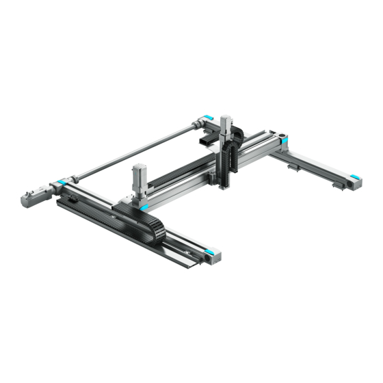
– The X-module moves the Y-module along the X-axis. – The Y-module moves customer-mounted attachments along the Y-axis. Fig. 1: Product version with EGC axes, example X-module connecting shaft Slide with Y-Z adapter plate X-module EHMX-EGC Y-module EHMY-RP-EGC Mounting attachment Festo — YXCF — 2021-07b... - Page 8 Product overview Fig. 2: Product version with ELGC axes, example X-module EHMX-ELGC Slide with Y-Z adapter plate Mounting attachment Y-module EHMY-RP-ELGC Festo — YXCF — 2021-07b...
-
Page 9: Modules Of The Product
– Energy chain (optional for product version with ELGC axes) – Multi-pin plug for sensors (optional) Product version with EGC axes Fig. 3: X-module EHMX-EGC-...-L, motor position left Motor (optional) Slide with X-Y adapter Connecting shaft Energy chain X-axis Multi-pin plug/sensors (optional) Festo — YXCF — 2021-07b... - Page 10 Connecting shaft Energy chain Motor (optional) X-axis Multi-pin plug/sensors (optional) Slide with X-Y adapter Fig. 5: X-module EHMX-EGC-...-M, motor position centre Motor (optional) Slide with X-Y adapter Connecting shaft Energy chain X-axis Multi-pin plug/sensors (optional) Festo — YXCF — 2021-07b...
- Page 11 Product overview Product version with ELGC axes Fig. 6: X-module EHMX-ELGC, motor position left axial, example Motor (optional) Support of the energy chain (optional) Slide with X-Y adapter Drive axis Guide axis Energy chain (optional) Festo — YXCF — 2021-07b...
-
Page 12: Y-Module
– Energy chain (optional for product version with ELGC axes) – Multi-pin plug for sensors (optional) Product version with EGC axis Fig. 7: Y-module EHMY-RP-EGC, motor position on right, example Energy chain Slide with Y-Z adapter plate Motor (optional) Y-axis Y-X adapter plate Festo — YXCF — 2021-07b... - Page 13 Product overview Product version with ELGC axis Fig. 8: Y-module EHMY-RP-ELGC, motor position left axial, example Energy chain (optional) Slide with Y-Z adapter plate Support of the energy chain (optional) Motor (optional) Y-axis Festo — YXCF — 2021-07b...
-
Page 14: Delivery Status
– Use suitable aids to lift and set down the product, e.g. crane. Lift the product out of the transportation protection with the mounted transport kit è 5.3.3 Lifting the product with the transport kit. Festo — YXCF — 2021-07b... -
Page 15: Remove Transportation Locks From The Transportation Protection
• Secure unsecured moving parts with transportation locks. Fig. 10: Identification of the transportation lock for moving parts • Do not remove the marked transportation locks for the moving parts until the product has been mounted. Festo — YXCF — 2021-07b... -
Page 16: Transport Kit
Lifting eye bolt (4x) Brace (2x) • Use the mounted transport kit to lift the product safely. Mounting lifting eye bolts on the mounting bracket Fig. 12: Mount the lifting eye bolt on the mounting bracket Festo — YXCF — 2021-07b... - Page 17 Mounting braces on X-axes Fig. 14: Mounting braces • For clamping the Y-width [By]: Fasten the braces to the mounting brackets with the screws and slot nuts. EHMX-EGC- Screw size M5 x 8 Tightening torque [Nm] Festo — YXCF — 2021-07b...
-
Page 18: Mounting The Transport Kit (Ehmx-Elgc)
Lifting eye bolt (4x) Brace (2x) Nut (4x) Slot nut (8x) Screw (4x) Screw (8x) Profile mounting (4x) Mounting bracket (4x) Slot nut (4x) • Use the mounted transport kit to lift the product safely. Festo — YXCF — 2021-07b... - Page 19 Fig. 17: Mounting braces • For clamping the Y-width [By]: Fasten the braces to the profile of the X-axes with the mounting profiles, screws and slot nuts. EHMX-ELGC- Screw size M5 x 10 Tightening torque [Nm] Festo — YXCF — 2021-07b...
-
Page 20: Lifting The Product With The Transport Kit
3. Tighten the nuts of the lifting eye bolts. Tightening torque: M8 = 12 Nm, M12 = 24 Nm Lifting the product with the mounted transport kit Requirement: the transportation locks for mounting on the transportation protection are removed. Festo — YXCF — 2021-07b... - Page 21 – Apply load to lifting eye bolts evenly at an angle of £ 45°. – Do not apply lateral stress to the lifting eye bolts. – Attach the lifting belts as vertically as possible: – Take adequate safety precautions. – Adjust the lifting speed. Festo — YXCF — 2021-07b...
-
Page 22: Removing Transportation Locks From The Moving Parts
– sufficient evenness WARNING Risk of injury due to falling product. • Make sure the mounting surface is sufficiently strong to absorb the maximum forces. • Only use the supplied mounting components. • Secure the screw connections. Festo — YXCF — 2021-07b... -
Page 23: Mounting Attachments
4426 … 4500 – Tab. 3: EHMX-EGC: number of required mounting components EHMX-ELGC- Mounting attachments [number per X-axis] £ 500 Stroke Hx [mm] in X-direction 600 … 1000 Tab. 4: EHMX-ELGC: number of required mounting components Festo — YXCF — 2021-07b... -
Page 24: Preparing Mounting Surface
2) Hx = stroke in X-direction è Technical data 3) n = number of mounting components per X-axis Tab. 5: Dimensions for mounting kit for EHMX-EGC EHMX-ELGC- [mm] By + 140 By + 180 [mm] Festo — YXCF — 2021-07b... - Page 25 X-axis. If necessary: move the mounting kits and change the dimension X2 accordingly. 4. With EHMX-EGC-...-M, motor position centre: Prepare the mounting for the motor è 6.3.3 Preparing motor mounting at centre motor position (EHMX-EGC-...-M). Festo — YXCF — 2021-07b...
-
Page 26: Preparing Mounting Surface For The Adjusting Kit
3) n = number of mounting components per X-axis Tab. 8: Dimensions for adjusting kit for EHMX-EGC EHMX-ELGC- [mm] By + 165 By + 205 [mm] 105 ± 5 125 ± 5 [mm] Hx – 69.5 Hx – 81.5 [mm] X1/(n – 1) Festo — YXCF — 2021-07b... - Page 27 X-axis. If necessary: move the adjusting kits and change the dimension X2 accordingly. 4. With EHMX-EGC-...-M, motor position centre: Prepare the mounting for the motor è 6.3.3 Preparing motor mounting at centre motor position (EHMX-EGC-...-M). Festo — YXCF — 2021-07b...
-
Page 28: Preparing Motor Mounting At Centre Motor Position (Ehmx-Egc
Tab. 11: EHMX-EGC-...-M with adjusting kit: dimensions for mounting motor/gear unit • Prepare the mounting holes on the mounting surface for secure mounting of the gear unit/motor. Make sure that the motor is placed outside the movement range of the Y-module. Festo — YXCF — 2021-07b... -
Page 29: Using Mounting Components
Strength class of screws at least 8.8 Mounting flange Screw (8x) Profile mounting (2x) Fig. 27: Mounting kit for EHMX-...-ELGC Strength class of the screws at least 10.9 The screws and their tightening torque are designed for mounting on steel. Festo — YXCF — 2021-07b... - Page 30 Tab. 12: Dimension of length offset A of the X-axes on the drive side 1. Loosen the screws on the profile mountings. Do not unscrew the screws. 2. Position the mounting kits on the prepared mounting surface. Festo — YXCF — 2021-07b...
- Page 31 4. Tighten the screws evenly on the profile mountings. EHMX-EGC- Screw size M3 x 7 M5 x 16 M8 x 20 M8 x 20 Tightening torque [Nm] EHMX-ELGC- Screw size M5 x 12 Tightening torque [Nm] Festo — YXCF — 2021-07b...
-
Page 32: Application Of Adjusting Kit
Washer (2x) Adjusting plate Adjusting bolt (2x) Fig. 30: Adjusting kit for EHMX -...- ELGC Strength class of the screws at least 10.9 The screws and their tightening torque are designed for mounting on steel Festo — YXCF — 2021-07b... - Page 33 With ELGC axes Size YXCF-1 … 4 YXCF-1-B YXCF-2-B X-module EHMX-EGC-… EHMX-ELGC-60 EHMX-ELGC-80 Length offset A [mm] 46.5 Tolerance ± 0.4 × (By/1000) Tab. 13: Dimension of length offset A of the X-axes on the drive side Festo — YXCF — 2021-07b...
- Page 34 2. Position the adjusting kits on the prepared mounting surface. 3. Tighten the screws on the underside. EHMX-EGC- Screw size M3 x 16 M5 x 25 M6 x 30 M6 x 30 Tightening torque [Nm] Festo — YXCF — 2021-07b...
- Page 35 3. Tighten the screws on the profile mountings. EHMX-ELGC- Screw size M5 x 16 Tightening torque [Nm] Fasten the adjusting kit to the mounting surface EHMX-ELGC- Screw size M8 x 40 Tightening torque [Nm] ³ 15 Screw-in depth m [mm] Festo — YXCF — 2021-07b...
- Page 36 3. Lightly secure the adjusting plate to the mounting surface with the screws. 4. Use an open-ended spanner with t < 5 mm. With t > 5 mm the maximum height compensation is reduced by the difference (t − 5) mm. Festo — YXCF — 2021-07b...
- Page 37 6. Tighten the screws. Hold the adjusting bolts while tightening the screws. Ä The adjusting bolt has not twisted. Ä The alignment has been maintained. Ä The minimum screw-in depth m of the screws is maintained. Festo — YXCF — 2021-07b...
-
Page 38: Product Assembly With "Partially Mounted" Delivery Status
Assembly Product assembly with “partially mounted” delivery status Fig. 33: Product version with EGC axes, example X-module connecting shaft Slide with Y-Z adapter plate X-module EHMX-EGC Y-module EHMY-RP-EGC Mounting attachment Festo — YXCF — 2021-07b... - Page 39 Assembly Fig. 34: Product version with ELGC axes, example X-module EHMX-ELGC Slide with Y-Z adapter plate Mounting attachment Y-module EHMY-RP-ELGC Screws Centring sleeves Fig. 35: Enclosed components, example Festo — YXCF — 2021-07b...
-
Page 40: Mounting X-Module
Fig. 36: X-module EHMX-EGC-...-L, motor position left Connecting shaft with motor X-axis X-axis with energy chain Fig. 37: X-module EHMX-EGC-...-R, motor position right Connecting shaft with motor X-axis with energy chain X-axis Fig. 38: X-module EHMX-EGC-...-M, motor position centre Festo — YXCF — 2021-07b... - Page 41 When mounting with mounting kits: the mounting surface must have the required flatness. When mounting with adjusting kits: unevenness of the mounting surface can be compensated. Fig. 40: Dimensions and limit values for alignment Length offset A of the X-axes on the drive side Festo — YXCF — 2021-07b...
- Page 42 Hx + 78 Hx + 118 Hx + 204 1) By = width in Y-direction è Technical data 2) Hx = stroke in X-direction è Technical data Tab. 19: Dimensions for adjusting kit for EHMX-EGC Festo — YXCF — 2021-07b...
- Page 43 Ä The guides of the X-axes must lie entirely in a theoretical plane with the required flatness. The required flatness depends on the size. 11. EHMX-EGC only: open the coupling on one side of the connecting shaft. Festo — YXCF — 2021-07b...
- Page 44 EHMX-EGC only: push both slides into the centre of the X-axes. Ä Check: slide offset £ 0.1 mm × (By/1000) 13. EHMX-EGC only: fasten the open coupling of the connecting shaft. Next step: • Mount the Y-module according to the product version. Festo — YXCF — 2021-07b...
-
Page 45: Mounting Y-Module
– The X-module is mounted. – The moving parts are secured with the transportation locks. Y-axis Y-X adapter plate Fig. 41: Y-module EHMY-RP-EGC, motor position left Y-axis Y-X adapter plate Fig. 42: Y-module EHMY-RP-EGC, motor position right Festo — YXCF — 2021-07b... - Page 46 Slacken the screws for fastening to the mounting surface on an X-axis, preferable the X-axis without energy chain, approximately 1 revolution. Apply counter pressure to the adjusting bolts with adjusting kits. Make sure that there is sufficient backlash in the mounting components of the detached X-axis for parallel alignment. Festo — YXCF — 2021-07b...
- Page 47 Tighten the screws evenly. EHMX-EGC- EHMY-RP-EGC- 80/125 120/160 185/220 Screw size M4 x 12 M5 x 12 M6 x 20 M8 x 20 Tightening torque [Nm] 6. Position the Y-module on the X-module in the middle. Festo — YXCF — 2021-07b...
- Page 48 Tightening torque [Nm] 8. Push the Y-module back and forth once by hand over the complete stroke length of the X-module. Ä The detached X-axis is aligned without tension and parallel to the mounted X-axis. Festo — YXCF — 2021-07b...
- Page 49 Tab. 22: EHMX-EGC with adjusting kit: screw size and tightening torque • Tighten all screws for mounting the X-axes on the mounting surface in accordance with the mounting component. Apply counter pressure to the adjusting bolts with adjusting kits. Festo — YXCF — 2021-07b...
- Page 50 On an X-axis, preferably on the guide axis, turn the screws approx. 1 revolution for mounting on the mounting surface. Apply counter pressure to the adjusting bolts with adjusting kits. Make sure that there is sufficient backlash in the mounting components of the detached X-axis for parallel alignment. Festo — YXCF — 2021-07b...
- Page 51 2. Place the Y-module on the X-Y adapters of the X-module. 3. Fasten the Y-module with the 4 profile mountings, 8 screws and slot nut to the 2 X-Y adapters of the X-module. Do not tighten the screws yet. Festo — YXCF — 2021-07b...
- Page 52 Clearances A/B between the angle profile of the XY adapter up to the cover of the Y-axis Clearance A: [mm] 42.7 on drive axis of the X- module (motor side) Clearance B: [mm] 75.2 66.6 83.4 on guide axis of the X-module (opposite motor side) Festo — YXCF — 2021-07b...
- Page 53 6. Move the Y-module by hand over the complete stroke length of the X-module. Ä The detached guide axis is aligned stress-free and parallel to the mounted drive axis of the X-module. 7. Push the Y-module into the centre of the X-axes. Festo — YXCF — 2021-07b...
- Page 54 Tab. 24: EHMX-ELGC with adjusting kit: screw size and tightening torque • Tighten all screws for mounting the X-axes on the mounting surface in accordance with the mounting component. Apply counter pressure to the adjusting bolts with adjusting kits. Festo — YXCF — 2021-07b...
-
Page 55: Mounting Connecting Shaft At Centre Of Motor Position (Ehmx-Egc
– The X-module is mounted. – Align the hollow shafts on the X-axes. Fig. 44: Motor position middle Shaft journal (2x) Gear unit/motor Clamping screw (2x) Size 185: plug (4x) Coupling (4x) Screw (12x) Connecting tube (2x) Festo — YXCF — 2021-07b... - Page 56 – Shaft journal; exception: leave the expanding mandrel cone greased on the inside. – Hollow shafts on the X-axes – Shaft journals on the gear unit The coupling will only grip without slipping if surfaces are dry and grease-free. Festo — YXCF — 2021-07b...
- Page 57 Mounting at the opposite ends of the X-axes is not permissible and would cause collisions. 4. Push the slides into the motor-side end position of the X-axes. Ä The hollow shafts no longer turn when the clamping screws are tightened. Festo — YXCF — 2021-07b...
- Page 58 7. If the expanding mandrel cone is stuck, the unit cannot be assembled. The shaft journal contains the extrusion thread G Screw a screw into G and press out the expanding mandrel cone. EHMX-EGC- Thread G Festo — YXCF — 2021-07b...
- Page 59 Assembly 8. Unscrew the screws on the half-shells. 9. Remove the half-shells. 10. Push the couplings onto the shaft journals to the stop. 11. Tighten the screw lightly. Ä The couplings are fixed. Festo — YXCF — 2021-07b...
- Page 60 Make sure that the shaft journal of the gear unit is aligned with the hollow shafts on the X-axes. 15. If there are featherkeys in the shaft journal of the gear unit: remove the featherkeys. 16. Push the couplings onto the shaft journals to the stop. Festo — YXCF — 2021-07b...
- Page 61 18. Place the connecting tubes in the coupling. 19. Loosen the screws of the couplings slightly. 20. Align the couplings centrally. 21. Observe push-in depth B of the shaft. EHMX-EGC- ³ 10.2 ³ 13.1 ³ 21.6 ³ 26 Push-in depth B [mm] Festo — YXCF — 2021-07b...
- Page 62 23. Position the half shells. Screw in the screws slightly. 24. Clamp the connecting tube to the half shell evenly and symmetrically. 25. Tighten the screws. EHMX-EGC- Screw size M4 x 16 M5 x 18 M10 x 30 M12 x 40 Tightening torque [Nm] Festo — YXCF — 2021-07b...
-
Page 63: Mounting Connecting Shaft At Motor Position Left/Right (Ehmx-Egc
Requirements: – The X-module is mounted. – Align the hollow shafts on the X-axes. Fig. 46: Motor position left/right Shaft journal (2x) Size 185: plug (2x) Clamping screw (2x) Connecting tube Coupling (2x) Screw (6x) Festo — YXCF — 2021-07b... - Page 64 – Shaft journal; exception: leave the expanding mandrel cone greased on the inside. – Hollow shafts on the X-axes – Shaft journals on the gear unit The coupling will only grip without slipping if surfaces are dry and grease-free. Festo — YXCF — 2021-07b...
- Page 65 Mounting at the opposite ends of the X-axes is not permissible and would cause collisions. 4. Push the slides into the motor-side end position of the X-axes. Ä The hollow shafts no longer turn when the clamping screws are tightened. Festo — YXCF — 2021-07b...
- Page 66 7. If the expanding mandrel cone is stuck, the unit cannot be assembled. The shaft journal contains the extrusion thread G Screw a screw into G and press out the expanding mandrel cone. EHMX-EGC- Thread G 8. Unscrew the screws on the half-shells. Festo — YXCF — 2021-07b...
- Page 67 Assembly 9. Remove the half-shells. 10. Push the couplings onto the shaft journals to the stop. 11. Tighten the screw lightly. Ä The couplings are fixed. Festo — YXCF — 2021-07b...
- Page 68 13. Place the connecting tube in the couplings. 14. Loosen the screws of the couplings slightly. 15. Align the couplings centrally. 16. Observe push-in depth B of the shaft. EHMX-EGC- ³ 10.2 ³ 13.1 ³ 21.6 ³ 26 Push-in depth B [mm] Festo — YXCF — 2021-07b...
- Page 69 18. Position the half shells. Screw in the screws slightly. 19. Clamp the connecting tube to the half shell evenly and symmetrically. 20. Tighten the screws. EHMX-EGC- Screw size M4 x 16 M5 x 18 M10 x 30 M12 x 40 Tightening torque [Nm] Festo — YXCF — 2021-07b...
-
Page 70: Product Assembly With Delivery Status "Completely Assembled
– The transportation kit for lifting the product is mounted. – The moving parts are secured with the transportation locks. Fig. 48: Product version with EGC axes, example X-module connecting shaft Slide with Y-Z adapter plate X-module EHMX-EGC Y-module EHMY-RP-EGC Mounting attachment Festo — YXCF — 2021-07b... - Page 71 Slide with Y-Z adapter plate Mounting attachment Y-module EHMY-RP-ELGC Mounting When mounting with mounting kits: the mounting surface must have the required flatness. When mounting with adjusting kits: unevenness of the mounting surface can be compensated. Festo — YXCF — 2021-07b...
- Page 72 1001 … 2000 2001 … 3000 3001 … 4000 4001 … 5000 1) The calculation of the dimensions X1 and Y1 depends on the mounting component used and the product version. Tab. 26: Requirements for alignment/evenness Festo — YXCF — 2021-07b...
- Page 73 Transport may have caused the product to become distorted. To remove distortion from the product and facilitate alignment of the X-axes: • Slightly loosen the connection between the X-module and Y-module; do not disconnect it. Festo — YXCF — 2021-07b...
- Page 74 On the left and right of the Y-module on the Y-X adapter plates 2 slacken the screws 3 maximum 1 revolution. Ä The Y-X adapter plates are loosened slightly at the profile of the Y-axis. Festo — YXCF — 2021-07b...
- Page 75 Check the alignment at the height of each position of the mounting components and adjust if necessary. Ä Check: – Evenness £ 0.1 mm × (Hx/1000) – Height offset and lateral tilt £ 0.1 mm × (By/1000) – Parallelism £ 0.1 mm × (By/1000) Festo — YXCF — 2021-07b...
- Page 76 Tighten the screws 3 on the left and right Y-module on the Y-X adapter plates. EHMX-EGC EHMY-RP-EGC- 80/125 120/160 185/220 Screw size M3 x 8 M5 x 12 M6 x 16 M6 x 16 Tightening torque [Nm] Festo — YXCF — 2021-07b...
- Page 77 Assembly Mounting Y-module on X-module (product version with ELGC axes) Fig. 54: Product version with ELGC axes: connection between X-module and Y-module Stop edge on the profile XY adapter Profile mounting bottom Profile mounting top Festo — YXCF — 2021-07b...
- Page 78 2. On the X-Y adapters on the left and right tighten the 8 screws of the top and bottom profile mountings evenly. Ä Check: – The upper profile mountings are in contact with the stop edges of the X-Y adapters. – Clearances A and B are maintained. Festo — YXCF — 2021-07b...
- Page 79 2. Push the Y-module back and forth once by hand over the complete stroke length of the X-module. Ä The detached X-axis is aligned without tension and parallel to the mounted X-axis. 3. Push the Y-module into the centre of the X-axes. Festo — YXCF — 2021-07b...
- Page 80 Apply counter pressure to the adjusting bolts with adjusting kits. • Check the alignment. Ä The guides of the X-axes must lie entirely in a theoretical plane with the required flatness. The required flatness depends on the size. Festo — YXCF — 2021-07b...
-
Page 81: Checking Structure And Alignment
Ä The module should be easily and evenly movable. If it is difficult to move at particular positions or over the entire length, this may be caused by offset or tension: align the product again. 2. For motor with brake: mount motor. Festo — YXCF — 2021-07b... -
Page 82: Motor With Brake
1. Mount the attachment component provided by the customer to the Y-Z adapter plate of the Y-module. Note the interface è CAD model of the product. 2. Earth the attachment component at the specified points è 7.2.4 Earthing. Festo — YXCF — 2021-07b... -
Page 83: Installation
-2 M1 Encoder cable (B1) -1 B1 -2 B1 Multi-pin plug 1 (X1) -1 X1 -2 X1 Multi-pin plug 2, – – optional (X2) Tab. 35: System of cable identification (product version with EGC axes) Festo — YXCF — 2021-07b... -
Page 84: Chamber Allocation For Energy Chain
The chambers are shown schematically from the point of view of the open end of the energy chain. Energy chain X-module Energy chain chambers Allocation Customer-specific Customer-specific Sensor cables, plug sockets with cable Encoder cables, earthing cable Motor cables or tubing Motor cables Tab. 38: Chamber allocation energy chain X-module EHMX-EGC Festo — YXCF — 2021-07b... - Page 85 Encoder cables or tubing Motor cables or tubing (optional) Sensor cables/plug sockets with cable or earthing cable (included) Tubing (optional) or customer-specific Earthing cable (intended) or customer-specific Tab. 41: Chamber allocation energy chain Y-module EHMY-RP-ELGC Festo — YXCF — 2021-07b...
-
Page 86: Installing Cables And Tubing
1. Move the energy chain through the entire stroke. Ä The energy chain must be able to move without hindrance. 2. In case of blockage: check and correct the installation of the cables and tubing. Festo — YXCF — 2021-07b... -
Page 87: Earthing
3. Earth the attachment component mounted by the customer. Earthing points The following illustration shows an example of the positions of the earthing points. The positions of the earthing points may vary depending on the configuration. Fig. 58: Earthing points, example Festo — YXCF — 2021-07b... - Page 88 Earthing point Washer Serrated washer 1. Position serrated washer. 2. Place the cable lugs of the earthing cables between the serrated washer and the washer. 3. Tighten the nut or screw. Tightening torque: 3.5 Nm Festo — YXCF — 2021-07b...
-
Page 89: Commissioning
• Check that the motor and gear housing is sufficiently fastened to the mounting surface. CAUTION Exposed, rotating connecting shaft. Risk of injury due to retraction or burning of body parts. • Install protective devices in the area of the connecting shaft, e.g. guard or covering. Festo — YXCF — 2021-07b... -
Page 90: Limit Switch
Commissioning Commissioning may only be performed by qualified specialised personnel who are familiar with: – Festo Configuration Tools (FCT)/Festo Automation Suite (FAS) – Installation and operation of handling systems Note the following during commissioning: – Never disconnect the plugs and electrical interfaces when powered. -
Page 91: Operation
Before disconnecting electrical connections: comply with the waiting time specified for the integrated electrical components è Observe the documentation of the electrical compo- nents. 2. Switch off compressed air supply. 3. Compressed air can be stored in the pneumatic attachment component: exhaust the attachment component. Festo — YXCF — 2021-07b... -
Page 92: Cleaning
The product is initially lubricated in the delivery status. NOTICE Trouble-free operation and a long service life require regular relubrication. • Lubricate the axes at the specified lubrication interval. • Observe the specifications for relubrication. • Use appropriate grease gun. Accessories è www.festo.com/catalogue. Specifications Lubrication interval [km] 2500 Lubricating grease See documentation for the axes è... -
Page 93: Fault Clearance
Too much offset Align axes/slides. scraping noise – Replace coupling. Coupling is broken at the con- Overload – Observe limit values. necting shaft. Too much offset – Align axes/slides. Torsional stresses Tab. 43: Fault clearance Festo — YXCF — 2021-07b... -
Page 94: Disassembly
Before disconnecting electrical connections: comply with the waiting time specified for the integrated electrical components è Observe the documentation of the electrical compo- nents. 3. Switch off compressed air supply. 4. Compressed air can be stored in the pneumatic attachment component: exhaust the attachment component. Festo — YXCF — 2021-07b... -
Page 95: Technical Data
Screws, centring pins Ball bearing Toothed belt pulleys, flanged High-alloy steel wheels Multi-pin retaining bracket Moment compensator Energy chains Plastic Buffer Cover caps Toothed belt Polychloroprene with glass cord and nylon coating Tab. 44: Technical data Festo — YXCF — 2021-07b... - Page 96 Copyright: Festo SE & Co. KG 73734 Esslingen Ruiter Straße 82 Deutschland Phone: +49 711 347-0 Internet: © 2021 all rights reserved to Festo SE & Co. KG www.festo.com...
Need help?
Do you have a question about the YXCF and is the answer not in the manual?
Questions and answers