
Related Manuals for HP HP 8719ET


Summary of Contents for HP HP 8719ET
- Page 1 Reference Guide HP 8719ET/20ET/22ET HP 8719ES/20ES/22ES Network Analyzers HP Part Number 08720-90393 Printed in USA August 1999 © Copyright 1999 Hewlett-Packard Company...
- Page 2 Notice The information contained in this document is subject to change without notice. Hewlett-Packard makes no warranty of any kind with regard to this material, including but not limited to, the implied warranties of merchantability and fitness for a particular purpose.
- Page 3 Certification Hewlett-Packard Company certifies that this product met its published specifications at the time of shipment from the factory. Hewlett-Packard further certifies that its calibration measurements are traceable to the United States National Institute of Standards and Technology, to the extent allowed by the Institute's calibration facility, and to the calibration facilities of other International Standards Organization members.
- Page 4 How to Use This Guide This guide uses the following conventions: This represents a key physically located on the Front-Panel Key instrument. This represents a “softkey,” a key whose label is SOFTKEY determined by the instrument’s firmware. This represents text displayed on the instrument’s screen. Screen Text...
- Page 5 The Service Guide is not part of a standard shipment and is available only as Option 0BW, or by ordering HP part number 08720-90397. A CD-ROM with the Service Guide in PDF format is included for viewing or printing from...
-
Page 7: Table Of Contents
Corrected System Performance (HP 8719/20ES) ........1-3... - Page 8 Contents 7. Options and Accessories Using This Chapter ............7-2 Analyzer Options Available .
- Page 9 Contents An Array of Data ............9-5 CITIfile Keyword .
- Page 10 Contents Contents-x...
- Page 11 HP 8719/20/22ES Specifications and Characteristics...
-
Page 12: Hp 8719/20/22Es Specifications And Characteristics
HP 8719/20/22ES Specifications and Characteristics Definitions Definitions All specifications and characteristics apply over a 23 °C ±3 °C range (unless otherwise stated) and 1/2 hour after the instrument has been turned on. Warranted performance. Specifications include guardbands to Specification (spec.): account for the expected statistical performance distribution, measurement uncertainties, and changes in performance due to environmental conditions. -
Page 13: Corrected System Performance (Hp 8719/20Es)
Assumes that an isolation calibration was performed with an averaging factor of 8. Table 1-1 System Dynamic Range, All Device Connector Types HP 8719/20ES, All Cal Kits, All Cables, 10 Hz IF BW Description Specification... - Page 14 HP 8719/20/22ES Specifications and Characteristics Corrected System Performance (HP 8719/20ES) Table 1-2 System Dynamic Range, All Device Connector Types HP 8722ES, All Cal Kits, All Cables, 10 Hz IF BW Description Specification Supplemental Information System Transmission Dynamic Range HP 8722ES (Standard)
- Page 15 Corrected System Performance (HP 8719/20ES) Table 1-3 3.5-mm Device Connector Type Network Analyzer: HP 8719ES/20ES, Standard Calibration Kit: HP 85052D (3.5-mm, 50 Ω) Cables: HP 85131F Calibration: Full 2-Port IF BW = 10 Hz, Avg off, Temp = 23 ± 3°C with < 1°C deviation from cal temp, Isol cal with avg = 8 Description Specification...
- Page 16 Corrected System Performance (HP 8719/20ES) Table 1-4 3.5-mm Device Connector Type Network Analyzer: HP 8719ES/20ES, Standard Calibration Kit: HP 85052B (3.5-mm, 50 Ω) Cables: HP 85131F Calibration: Full 2-Port IF BW = 10 Hz, Avg off, Temp = 23 ± 3°C with < 1°C deviation from cal temp, Isol cal with avg = 8 Description Specification...
- Page 17 Corrected System Performance (HP 8719/20ES) Table 1-5 3.5-mm Device Connector Type Network Analyzer: HP 8719ES/20ES, Option 400 Calibration Kit: HP 85052C (3.5-mm, 50 Ω) Cables: HP 85131F Calibration: TRL IF BW = 10 Hz, Avg off, Temp = 23 ± 3°C with < 1°C deviation from cal temp, Isol cal with avg = 8 Description Specification...
- Page 18 Corrected System Performance (HP 8719/20ES) Table 1-6 3.5-mm Device Connector Type Network Analyzer: HP 8719ES/20ES, Option 007 Calibration Kit: HP 85052B (3.5-mm with Sliding Loads, 50 Ω) Cables: HP 85132F Calibration: Full 2-Port IF BW = 10 Hz, Avg off, Temp = 23 ± 3°C with < 1°C deviation from cal temp, Isol cal with avg = 8 Description Specification...
- Page 19 Corrected System Performance (HP 8719/20ES) Table 1-7 3.5-mm Device Connector Type Network Analyzer: HP 8719ES/20ES, Option 007 Calibration Kit: HP 85052D (3.5-mm 50 Ω) Cables: HP 85132F Calibration: Full 2-Port IF BW = 10 Hz, Avg off, Temp = 23 ± 3°C with < 1°C deviation from cal temp, Isol cal with avg = 8 Description Specification...
- Page 20 Corrected System Performance (HP 8719/20ES) Table 1-8 7-mm Device Connector Type Network Analyzer: HP 8719ES/20ES, Standard Calibration Kit: HP 85050B (7-mm, 50 Ω) Cables: HP 85132F Calibration: Full 2-Port IF BW = 10 Hz, Avg off, Temp = 23 ± 3°C with < 1°C deviation from cal temp, Isol cal with avg = 8 Description Specification...
- Page 21 Corrected System Performance (HP 8719/20ES) Table 1-9 7-mm Device Connector Type Network Analyzer: HP 8719ES/20ES, Option 400 Calibration Kit: HP 85050C (7-mm, 50 Ω) Cables: HP 85132F Calibration: TRL IF BW = 10 Hz, Avg off, Temp = 23 ± 3°C with < 1°C deviation from cal temp, Isol cal with avg = 8 Description Specification...
- Page 22 Corrected System Performance (HP 8719/20ES) Table 1-10 Type-N Device Connector Type Network Analyzer: HP 8719ES/20ES, Standard Calibration Kit: HP 85054D (Type-N, 50 Ω) Cables: HP 85132F Calibration: Full 2-Port IF BW = 10 Hz, Avg off, Temp = 23 ± 3°C with < 1°C deviation from cal temp, Isol cal with avg = 8 Description Specification...
- Page 23 Corrected System Performance (HP 8719/20ES) Table 1-11 Type-N Device Connector Type Network Analyzer: HP 8719ES/20ES, Standard Calibration Kit: HP 85054B (Type-N, 50 Ω) Cables: HP 85132F Calibration: Full 2-Port IF BW = 10 Hz, Avg off, Temp = 23 ± 3°C with < 1°C deviation from cal temp, Isol cal with avg = 8 Description Specification...
-
Page 24: Corrected System Performance (Hp 8722Es)
HP 8719/20/22ES Specifications and Characteristics Corrected System Performance (HP 8722ES) Corrected System Performance (HP 8722ES) The specifications in this section apply for measurements made using 10 Hz IF bandwidth, no averaging, and at an environmental temperature of 23 ±3 °C, with less than 1 °C deviation from the calibration temperature. - Page 25 Corrected System Performance (HP 8722ES) Table 1-12 2.4-mm Device Connector Type Network Analyzer: HP 8722ES, Standard Calibration Kit: HP 85056A (2.4-mm, 50 Ω) Cables: HP 85133F Calibration: Full 2-Port IF BW = 10 Hz, Avg off, Temp = 23 ± 3°C with < 1°C deviation from cal temp, Isol cal with avg = 8 Description Specification...
- Page 26 Corrected System Performance (HP 8722ES) Table 1-13 2.4-mm Device Connector Type Network Analyzer: HP 8722ES, Standard Calibration Kit: HP 85056D (2.4-mm, 50 Ω) Cables: HP 85133F Calibration: Full 2-Port IF BW = 10 Hz, Avg off, Temp = 23 ± 3°C with < 1°C deviation from cal temp, Isol cal with avg = 8 Description Specification...
- Page 27 Corrected System Performance (HP 8722ES) Table 1-14 3.5-mm Device Connector Type Network Analyzer: HP 8722ES, Standard Calibration Kit: HP 85052D (3.5-mm, 50 Ω) Cables: HP 85131F Calibration: Full 2-Port IF BW = 10 Hz, Avg off, Temp = 23 ± 3°C with < 1°C deviation from cal temp, Isol cal with avg = 8 Description Specification...
- Page 28 Corrected System Performance (HP 8722ES) Table 1-15 3.5-mm Device Connector Type Network Analyzer: HP 8722ES, Standard Calibration Kit: HP 85052B (3.5-mm, 50 Ω) Cables: HP 85131F Calibration: Full 2-Port IF BW = 10 Hz, Avg off, Temp = 23 ± 3°C with < 1°C deviation from cal temp, Isol cal with avg = 8 Description Specification...
- Page 29 Corrected System Performance (HP 8722ES) Table 1-16 3.5-mm Device Connector Type Network Analyzer: HP 8722ES, Option 400 Calibration Kit: HP 85052C (3.5-mm, 50 Ω) Cables: HP 85131F Calibration: TRL IF BW = 10 Hz, Avg off, Temp = 23 ± 3 °C with < 1 °C deviation from cal temp, Isol cal with avg = 8 Description Specification...
- Page 30 Corrected System Performance (HP 8722ES) Table 1-17 Type-N Device Connector Type Network Analyzer: HP 8722ES, Standard Calibration Kit: HP 85054D (Type-N, 50 Ω) Cables: HP 85132F Calibration: Full 2-Port IF BW = 10 Hz, Avg off, Temp = 23 ± 3 °C with < 1 °C deviation from cal temp, Isol cal with avg = 8 Description Specification...
- Page 31 Corrected System Performance (HP 8722ES) Table 1-18 2.4-mm Device Connector Type Network Analyzer: HP 8722ES, Option 007 Calibration Kit: HP 85056A (2.4-mm with sliding loads, 50 Ω) Cables: HP 85133F Calibration: Full 2-Port IF BW = 10 Hz, Avg off, Temp = 23 ± 3 °C with < 1 °C deviation from cal temp, Isol cal with avg = 8 Description Specification...
- Page 32 Corrected System Performance (HP 8722ES) Table 1-19 2.4-mm Device Connector Type Network Analyzer: HP 8722ES, Option 007 Calibration Kit: HP 85056D (2.4-mm 50 Ω) Cables: HP 85133F Calibration: Full 2-Port IF BW = 10 Hz, Avg off, Temp = 23 ± 3 °C with < 1 °C deviation from cal temp, Isol cal with avg = 8 Description Specification...
- Page 33 Corrected System Performance (HP 8722ES) Table 1-20 Type-N Device Connector Type Network Analyzer: HP 8722ES, Standard Calibration Kit: HP 85054B (Type-N, 50 Ω) Cables: HP 85132F Calibration: Full 2-Port IF BW = 10 Hz, Avg off, Temp = 23 ± 3 °C with < 1 °C deviation from cal temp, Isol cal with avg = 8 Description Specification...
-
Page 34: Instrument Specifications
HP 8719/20/22ES Specifications and Characteristics Instrument Specifications Instrument Specifications Uncorrected Port Performance Table 1-21 3.5-mm Device Connector Type HP 8719ES/20ES (3.5-mm, 50 Ω) Characteristic Description 50 to 500 MHz 0.5 to 2 GHz 2 to 8 GHz 8 to 20 GHz... - Page 35 HP 8719/20/22ES Specifications and Characteristics Instrument Specifications Table 1-22 2.4-mm Device Connector Type HP 8722ES (2.4-mm, 50 Ω) Description Characteristic 50 to 0.5 to 2 to 8 to 20 to 500 MHz 2 GHz 8 GHz 20 GHz 40 GHz...
-
Page 36: Test Port Output
HP 8719/20/22ES Specifications and Characteristics Instrument Specifications Test Port Output Table 1-23 Test Port Output HP 8719ES/20ES/22ES Test Port Output Description Specification Supplemental Information Frequency Range HP 8719ES 0.05 to 13.51 GHz HP 8720ES 0.05 to 20.05 GHz HP 8722ES 0.05 to 40.05 GHz... - Page 37 HP 8719/20/22ES Specifications and Characteristics Instrument Specifications Table 1-24 Test Port Output HP 8719ES/20ES/22ES Test Port Output Description Specification Supplemental Information Output Power Maximum Leveled Power HP 8719/20ES (Standard) +5 dBm, char. HP 8719ES/20ES (Option 007) +10 dBm, char. HP 8722ES (Standard) −5 dBm, char.
- Page 38 HP 8719/20/22ES Specifications and Characteristics Instrument Specifications Table 1-25 Test Port Output HP 8719ES/20ES Test Port Output Description Specification Supplemental Information Output Power Power Resolution 0.01 dB Attenuator Switch Points: Note: For Option 400, the switch point between Range 0 and Range 1 is −10 dBm.
- Page 39 HP 8719/20/22ES Specifications and Characteristics Instrument Specifications Table 1-26 Test Port Output HP 8722ES Test Port Output Description Specification Supplemental Information Output Power Power Resolution 0.01 dB Attenuator Switch Points: Note: For Option 400, the switch point between Range 0 and Range 1 is 0 dBm.
- Page 40 Supplemental Information Test Reference Powers: Linearity Standard HP 8719/20ES: −5 dBm −5 dB from reference ±0.35 dB HP 8719/20ES Option 007: 0 dBm ±0.35 dB +5 dB from reference −10 dB from reference ±0.6 dB ±1.0 dB +10 dB from reference Impedance 50 Ω, nominal...
- Page 41 Specification Supplemental Information Test Reference Powers: Linearity Standard HP 8722ES: −10 dBm −5 dB from reference HP 8722ES Option 007: −5 dBm ±0.35 dB 50 MHz to 20 GHz ±0.6 dB 20 GHz to 40 GHz +5 dB from reference ±0.35 dB...
- Page 42 HP 8719/20/22ES Specifications and Characteristics Instrument Specifications Table 1-29 Test Port Output HP 8719ES/20ES/22ES Test Port Output Description Specification Supplemental Information Signal Purity 2nd Harmonic 0.05 GHz to one half the maximum source frequency < −15 dBc, typ. at the maximum output level...
-
Page 43: Test Port Input
HP 8719/20/22ES Specifications and Characteristics Instrument Specifications Test Port Input Table 1-30 Test Port Input HP 8719ES/20ES/22ES Test Port Input Description Specification Supplemental Information Frequency Range HP 8719ES 0.05 to 13.51 GHz HP 8720ES 0.05 to 20.05 GHz HP 8722ES 0.05 to 40.05 GHz... - Page 44 HP 8719/20/22ES Specifications and Characteristics Instrument Specifications Table 1-31 Test Port Input HP 8719ES/20ES/22ES Test Port Input Description Specification Supplemental Information 0.1 dB Compression (Option 012), direct receiver input −5 dBm, typ. 0.05 to 0.5 GHz −5 dBm, typ. 0.5 to 2 GHz −5 dBm, typ.
- Page 45 HP 8719/20/22ES Specifications and Characteristics Instrument Specifications Table 1-32 Test Port Input HP 8719/20/22ES Test Port Input Description Supplemental Information System Bandwidths 3000 Hz 10 Hz Trace Noise Magnitude 0.05 GHz to 13.5 GHz < 0.03 dB rms, typ. < 0.003 dB rms, typ.
- Page 46 HP 8719/20/22ES Specifications and Characteristics Instrument Specifications Table 1-34 Test Port Input HP 8719/20ES Test Port Input Dynamic Accuracy (Characteristic) For input ports 1 and 2, accuracy of the test port input power reading relative to the reference input power level.
- Page 47 HP 8719/20/22ES Specifications and Characteristics Instrument Specifications Table 1-34 Test Port Input HP 8719/20ES Test Port Input 1-37...
- Page 48 HP 8719/20/22ES Specifications and Characteristics Instrument Specifications Table 1-35 Test Port Input HP 8722ES Test Port Input Dynamic Accuracy (Characteristic) For input ports 1 and 2, accuracy of the test port input power reading relative to the reference input power level.
- Page 49 HP 8719/20/22ES Specifications and Characteristics Instrument Specifications Table 1-35 Test Port Input HP 8722ES Test Port Input 1-39...
-
Page 50: General Information
HP 8719/20/22ES Specifications and Characteristics Instrument Specifications General Information Table 1-36 General Information HP 8719/20/22ES General Information Description Specification Supplemental Information Display Range ±200 dB (at 20 dB/div), max Magnitude ±180°, max Phase Polar 10 pico units, min 1000 units, max... - Page 51 HP 8719/20/22ES Specifications and Characteristics Instrument Specifications Table 1-37 General Information HP 8719/20/22ES General Information Description Specification Supplemental Information Group Delay Aperture (selectable) (frequency span)/(number of points −1) Maximum Aperture 20% of frequency span with smoothing enabled 1/2 × (1/minimum aperture)
- Page 52 HP 8719/20/22ES Specifications and Characteristics Instrument Specifications Table 1-38 General Information HP 8719/20/22ES General Information Description Supplemental Information System Bandwidths IF bandwidth settings 6000 Hz, nom. 3700 Hz, nom. 3000 Hz, nom. 1000 Hz nom. 300 Hz, nom. 100 Hz, nom.
- Page 53 HP 8719/20/22ES Specifications and Characteristics Instrument Specifications Table 1-39 General Information HP 8719/20/22ES General Information Description Specification Supplemental Information Rear Panel Test Port Bias Input ±40 Vdc Maximum voltage ±500 mA Maximum current External Reference In 1, 2, 5, and 10 MHz ±200 Hz at 10 MHz Input Frequency −10 dBm to +20 dBm, typ.
- Page 54 HP 8719/20/22ES Specifications and Characteristics Instrument Specifications Table 1-40 General Information HP 8719/20/22ES General Information Description Specification Front Panel Display Pixel Integrity Red, Green, or Blue Pixels Red, green, or blue "stuck on" pixels may appear against a black background. In a...
- Page 55 HP 8719/20/22ES Specifications and Characteristics Instrument Specifications Table 1-41 General Information HP 8719/20/22ES General Information Description Specification Supplemental Information General Environmental RFI/EMI Susceptibility Defined by CISPR Pub. 11 and FCC Class B standards. Minimize using static-safe work procedures and an antistatic bench mat (HP part number 9300-0797).
-
Page 56: Speed Parameters
HP 8719/20/22ES Specifications and Characteristics Instrument Specifications Speed Parameters Table 1-42 HP 8719/20/22ES Measurement and Data Transfer Speed Performance Typical Time for Completion (ms) Number of Points Description 1601 Swept Stepped Swept Stepped Swept Stepped Swept Stepped Typical Time for Completion (in ms), Start 1 GHz, Span 10 MHz, IFWB=6000... - Page 57 0.778 0.471 0.364 Sweep only (no Recall) Dual Chan. 1601 0.420 0.414 Instrument State: CF = 1 GHz, Span = 2 MHz, IF BW = 6 kHz. HP-IB commands sent for timing are Recall;OPC?;SING; or, for sweep only, OPC?;SING;. 1-47...
- Page 58 HP 8719/20/22ES Specifications and Characteristics Instrument Specifications Table 1-44 Sweep Time vs. IF Bandwidth IF Bandwidth Typical Sweep Time (seconds) 6000 0.066 3700 0.091 3000 0.116 1000 0.243 0.700 2.018 7.058 21.475 a. Preset condition, CF = 1 GHz, Span = 100 MHz; includes retrace time, 201 points.
-
Page 59: Power Meter Calibration Accuracy
HP 8719/20/22ES Specifications and Characteristics Instrument Specifications Power Meter Calibration Accuracy Table 1-46 Power Meter Calibration Sweep Speed and Accuracy Power Desired at Number of Sweep Time Characteristic Test Port Readings Setting (seconds) Accuracy (dB) ±0.7 +5 dBm ±0.2 ±0.1 ±0.7... - Page 60 HP 8719/20/22ES Specifications and Characteristics Instrument Specifications 1-50...
- Page 61 HP 8719/20/22ET Specifications and Characteristics...
-
Page 62: Hp 8719/20/22Et Specifications And Characteristics
HP 8719/20/22ET Specifications and Characteristics Definitions Definitions All specifications and characteristics apply over a 23 °C ±3 °C range (unless otherwise stated) and 1/2 hour after the instrument has been turned on. Warranted performance. Specifications include guardbands to Specification (spec.): account for the expected statistical performance distribution, measurement uncertainties, and changes in performance due to environmental conditions. -
Page 63: Corrected System Performance (Hp 8719/20Et)
Assumes that an isolation calibration was performed with an averaging factor of 8. Table 2-1 System Dynamic Range, All Device Connector Types HP 8719/20ET, All Options, All Cal Kits, All Cables, 10 Hz IF BW Description Specification... - Page 64 HP 8719/20/22ET Specifications and Characteristics Corrected System Performance (HP 8719/20ET) Table 2-3 3.5-mm (50 Ω) Device Connector Type Network Analyzer: HP 8719/20ET Standard or Option 004 Attenuator Calibration Kit: HP 85052B (3.5-mm, 50 Ω) Cal Kit Cables: HP 85131E Cables Calibration: One-Port, Response, or Enhanced Response IF BW = 10 Hz, Avg = off, Temp = 23 ±...
- Page 65 HP 8719/20/22ET Specifications and Characteristics Corrected System Performance (HP 8719/20ET) Transmission Uncertainty: Enhanced Response Calibration (Specification) Transmission Uncertainty: Response Calibration (Specification) Reflection Uncertainty: One-Port Calibration (Specification) a. Option 004 may degrade transmission source match as much as 2 dB, resulting in up to...
-
Page 66: Corrected System Performance (Hp 8722Et)
HP 8719/20/22ET Specifications and Characteristics Corrected System Performance (HP 8722ET) Corrected System Performance (HP 8722ET) The specifications in this section apply for measurements made using 10 Hz IF bandwidth, no averaging, and at an environmental temperature of 23 ±3 °C, with less than 1 °C deviation from the calibration temperature. - Page 67 HP 8719/20/22ET Specifications and Characteristics Corrected System Performance (HP 8722ET) Table 2-4 2.4-mm (50 Ω) Device Connector Type Network Analyzer: HP 8722ET Standard or Option 004 Attenuator Calibration Kit: HP 85056A (2.4-mm, 50 Ω) Cables: HP 85133E Cables Calibration: One-Port, Response, or Enhanced Response IF BW = 10 Hz, Avg = off, Temp = 23 ±...
- Page 68 HP 8719/20/22ET Specifications and Characteristics Corrected System Performance (HP 8722ET) Transmission Uncertainty: Enhanced Response Calibration (Specification) Transmission Uncertainty: Response Calibration (Specification) Reflection Uncertainty: One-Port Calibration (Specification) a. Option 004 may degrade transmission source match as much as 2 dB, resulting in up to...
-
Page 69: Instrument Specifications
HP 8719/20/22ET Specifications and Characteristics Instrument Specifications Instrument Specifications Uncorrected Port Performance Table 2-5 3.5-mm (50 Ω) Device Connector Type HP 8719/20ET (3.5-mm, 50 Ω) Specification Description 50 to 500 MHz 0.5 to 2 GHz 2 to 8 GHz 8 to 20 GHz... - Page 70 HP 8719/20/22ET Specifications and Characteristics Instrument Specifications Table 2-6 2.4-mm (50 Ω) Device Connector Type HP 8722ET (2.4-mm, 50 Ω) Specification Description 0.5 to 2 GHz 2 to 8 GHz 8 to 20 GHz 20 to 40 GHz 50 to 500 MHz...
-
Page 71: Test Port Output
HP 8719/20/22ET Specifications and Characteristics Instrument Specifications Test Port Output Table 2-7 Test Port Output HP 8719ET/20ET/22ET Test Port Output Description Specification Supplemental Information Frequency Range HP 8719ET 0.05 to 13.51 GHz HP 8720ET 0.05 to 20.05 GHz HP 8722ET 0.05 to 40.05 GHz... - Page 72 HP 8719/20/22ET Specifications and Characteristics Instrument Specifications Table 2-8 Test Port Output HP 8719ET/20ET/22ET Test Port Output Description Specification Supplemental Information Output Power Level Accuracy ± 2 dB HP 8719ET/20ET at 5 dBm ± 3 dB at −5 dBm HP 8722ET...
- Page 73 HP 8719/20/22ET Specifications and Characteristics Instrument Specifications Table 2-9 Test Port Output HP 8719ET/20ET Test Port Output Description Specification Supplemental Information Output Power (Option 004 Only) Power Resolution 0.01 dB Attenuator Switch Points: 2-13...
- Page 74 HP 8719/20/22ET Specifications and Characteristics Instrument Specifications Table 2-10 Test Port Output HP 8722ET Test Port Output Description Specification Supplemental Information Output Power (Option 004 Only) Power Resolution 0.01 dB Attenuator Switch Points: 2-14...
- Page 75 HP 8719/20/22ET Specifications and Characteristics Instrument Specifications Table 2-11 Test Port Output HP 8719ET/20ET Test Port Output Description Specification Supplemental Information Output Power Test Reference Power: 0 dBm Linearity −5 dB from reference ± 0.35 dB ± 0.35 dB +5 dB from reference −10 dB from reference...
- Page 76 HP 8719/20/22ET Specifications and Characteristics Instrument Specifications Table 2-12 Test Port Output HP 8722ET Test Port Output Description Specification Supplemental Information Output Power Test Reference Power: −5 dBm Linearity −5 dB from reference ± 0.35 dB 50 MHz to 20 GHz ±...
-
Page 77: Test Port Input
HP 8719/20/22ET Specifications and Characteristics Instrument Specifications Test Port Input Table 2-13 Test Port Input HP 8719ET/20ET/22ET Test Port Input Description Specification Supplemental Information Frequency Range HP 8719ET 0.05 to 13.51 GHz HP 8720ET 0.05 to 20.05 GHz HP 8722ET 0.05 to 40.05 GHz... - Page 78 HP 8719/20/22ET Specifications and Characteristics Instrument Specifications Table 2-14 Test Port Input HP 8719/20/22ET Test Port Input Description Supplemental Information System Bandwidths 3000 Hz 10 Hz Trace Noise Magnitude 0.05 GHz to 13.5 GHz < 0.03 dB rms, typ. < 0.003 dB rms, typ.
- Page 79 HP 8719/20/22ET Specifications and Characteristics Instrument Specifications Table 2-15 Test Port Input HP 8719/20/22ET Test Port Input Description Specification Supplemental Information Reference Level Magnitude ± 500 dB Range Resolution 0.001 dB Phase ± 500° Range Resolution 0.01° 2-19...
- Page 80 HP 8719/20/22ET Specifications and Characteristics Instrument Specifications Table 2-16 Test Port Input HP 8719/20ET Test Port Input (Transmission) Dynamic Accuracy (Characteristic) For transmission accuracy of the test port input power reading relative to the reference input power level. • Inputs: transmission port •...
- Page 81 HP 8719/20/22ET Specifications and Characteristics Instrument Specifications Table 2-16 Test Port Input HP 8719/20ET Test Port Input (Transmission) 2-21...
- Page 82 HP 8719/20/22ET Specifications and Characteristics Instrument Specifications Table 2-17 Test Port Input HP 8719/20ET Test Port Input (Reflection) Dynamic Accuracy (Characteristic) For reflection accuracy of the test port input power reading relative to the reference input power level. • Inputs: reflection port •...
- Page 83 HP 8719/20/22ET Specifications and Characteristics Instrument Specifications Table 2-17 Test Port Input HP 8719/20ET Test Port Input (Reflection) 2-23...
- Page 84 HP 8719/20/22ET Specifications and Characteristics Instrument Specifications Table 2-18 Test Port Input HP 8722ET Test Port Input (Transmission) Dynamic Accuracy (Characteristic) For transmission accuracy of the test port input power reading relative to the reference input power level. • Inputs: transmission port •...
- Page 85 HP 8719/20/22ET Specifications and Characteristics Instrument Specifications Table 2-18 Test Port Input HP 8722ET Test Port Input (Transmission) 2-25...
- Page 86 HP 8719/20/22ET Specifications and Characteristics Instrument Specifications Table 2-19 Test Port Input HP 8722ET Test Port Input (Reflection) Dynamic Accuracy (Characteristic) For reflection accuracy of the test port input power reading relative to the reference input power level. • Inputs: reflection port •...
- Page 87 HP 8719/20/22ET Specifications and Characteristics Instrument Specifications Table 2-19 Test Port Input HP 8722ET Test Port Input (Reflection) 2-27...
-
Page 88: General Information
HP 8719/20/22ET Specifications and Characteristics Instrument Specifications General Information Table 2-20 General Information HP 8719/20/22ET General Information Description Specification Supplemental Information Display Range ± 200 dB (at 20 dB/div), max Magnitude ± 180°, max Phase Polar 10 pico units, min... - Page 89 HP 8719/20/22ET Specifications and Characteristics Instrument Specifications Table 2-21 General Information HP 8719/20/22ET General Information Description Specification Supplemental Information Group Delay Aperture (selectable) (frequency span)/(number of points − 1) Maximum Aperture 20% of frequency span 1/2 × (1/minimum aperture) Range...
- Page 90 HP 8719/20/22ET Specifications and Characteristics Instrument Specifications Table 2-22 General Information HP 8719/20/22ET General Information Description Supplemental Information System Bandwidths IF bandwidth settings 6000 Hz, nom. 3700 Hz, nom. 3000 Hz, nom. 1000 Hz nom. 300 Hz, nom. 100 Hz, nom.
- Page 91 HP 8719/20/22ET Specifications and Characteristics Instrument Specifications Table 2-23 General Information HP 8719/20/22ET General Information Description Specification Supplemental Information Rear Panel External Reference In 1, 2, 5, and 10 MHz ± 200 Hz at 10 MHz Input Frequency −10 dBm to +20 dBm, typ.
- Page 92 HP 8719/20/22ET Specifications and Characteristics Instrument Specifications Table 2-24 General Information HP 8719/20/22ET General Information Description Specification Front Panel Display Pixel Integrity Red, Green, or Blue Pixels Red, green, or blue "stuck on" pixels may appear against a black background. In a...
- Page 93 HP 8719/20/22ET Specifications and Characteristics Instrument Specifications Table 2-25 General Information HP 8719/20/22ET General Information Description Specification Supplemental Information General Environmental RFI/EMI Susceptibility Defined by CISPR Pub. 11 and FCC Class B standards. Minimize using static-safe work procedures and an antistatic bench mat (HP part number 9300-0797).
-
Page 94: Speed Parameters
HP 8719/20/22ET Specifications and Characteristics Instrument Specifications Speed Parameters Table 2-26 HP 8719/20/22ET Measurement and Data Transfer Speed Performance Typical Time for Completion (ms) Number of Points Description 1601 Swept Stepped Swept Stepped Swept Stepped Swept Stepped Typical Time for Completion (in ms), Start 1 GHz, Span 10 MHz, IFWB=6000... - Page 95 0.778 0.471 0.364 Sweep only (no Recall) Dual Chan. 1601 0.420 0.414 Instrument State: CF = 1 GHz, Span = 2 MHz, IF BW = 6 kHz. HP-IB commands sent for timing are Recall;OPC?;SING; or, for sweep only, OPC?;SING;. 2-35...
- Page 96 HP 8719/20/22ET Specifications and Characteristics Instrument Specifications Table 2-28 Sweep Time vs. IF Bandwidth IF Bandwidth Typical Sweep Time (seconds) 6000 0.066 3700 0.091 3000 0.116 1000 0.243 0.700 2.018 7.058 21.475 a. Preset condition, CF = 1 GHz, Span = 100 MHz; includes retrace time, 201 points.
- Page 97 HP 8719/20/22ET Specifications and Characteristics Instrument Specifications Power Meter Calibration Accuracy Table 2-30 Power Meter Calibration Sweep Speed and Accuracy Power Desired at Number of Sweep Time Characteristic Test Port Readings Setting (seconds) Accuracy (dB) ±0.7 +5 dBm ±0.2 ±0.1 −15 dBm...
- Page 98 HP 8719/20/22ET Specifications and Characteristics Instrument Specifications 2-38...
-
Page 99: Front/Rear Panel
Front/Rear Panel... -
Page 100: Front Panel Features
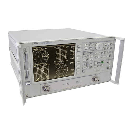
Do not mistake the line switch for the disk eject button. See the following illustrations. If the line switch is mistakenly pushed, the instrument will be turned off, losing all settings and data that have not been saved. Figure 3-1 HP 8719/20/22ES Front Panel Figure 3-2 HP 8719/20/22ET Front Panel... - Page 101 Front/Rear Panel Front Panel Features The location of the following front panel features and key function blocks is shown in Figure 3-1 Figure 3-2. These features are described in more detail later in this chapter, and in Chapter 5 , “Hardkey/Softkey Reference.” LINE switch.
- Page 102 • frequency offset mode (Option 089) • test sequence function • time domain transform (Option 010) HP-IB STATUS indicators are also included in this block. key. This key returns the instrument to either a known factory Preset preset state, or a user preset state that can be defined. Refer to Chapter 8 , “Preset State and Memory Allocation”...
-
Page 103: Analyzer Display
Front/Rear Panel Analyzer Display Analyzer Display Figure 3-3 Analyzer Display (Single Channel, Cartesian Format) The analyzer display shows various measurement information: • The grid where the analyzer plots the measurement data. • The currently selected measurement parameters. • The measurement data traces. Figure 3-3 illustrates the locations of the different information labels described below. - Page 104 Front/Rear Panel Analyzer Display Stimulus Start Value. This value could be any one of the following: • The start frequency of the source in frequency domain measurements. • The start time in CW mode (0 seconds) or time domain measurements. •...
- Page 105 Front/Rear Panel Analyzer Display C2 (ES) Full two-port error-correction is on and the reverse sweep is not updated each sweep Any one of the following causes the reverse sweep not to be updated each sweep: • the instrument uses a mechanical switch, for example Options 85 and 007.
- Page 106 Front/Rear Panel Analyzer Display Source power is unleveled at start or stop of sweep. (Refer to the service guide for troubleshooting.) P↓ Source power has been automatically set to minimum, due to receiver overload. (See Chapter 5 , POWER “Hardkey/Softkey Reference.”) (ES or ET Option 004.) Power range is in manual mode.
- Page 107 Front/Rear Panel Analyzer Display Measured Input(s). This shows the parameter, input, or ratio of inputs currently measured, as selected using the key. Also indicated in Meas this area is the current display memory status. Format. This is the display format that you selected using the Format key.
-
Page 108: Rear Panel Features And Connectors
Requirements for input signals to the rear panel connectors are provided in the specifications and characteristics chapter. HP-IB connector. This allows you to connect the analyzer to an external controller, compatible peripherals, and other instruments for an automated system. Refer to Chapter 7 , “Options and Accessories”... - Page 109 Front/Rear Panel Rear Panel Features and Connectors KEYBOARD input (mini-DIN). This connector allows you to connect an external keyboard. This provides a more convenient means to enter a title for storage files, as well as substitute for the analyzer's front panel keyboard.
- Page 110 Front/Rear Panel Rear Panel Features and Connectors LIMIT TEST. This outputs a TTL signal of the limit test results as follows: • Pass: TTL high • Fail: TTL low MEASURE RESTART. This allows the connection of an optional foot switch. Using the foot switch will duplicate the key sequence Meas MEASURE RESTART TEST SET INTERCONNECT.
-
Page 111: Menu Maps
Menu Maps... - Page 112 Menu Maps Menu Maps Menu Maps This chapter contains menus maps for the hardkeys listed below. The figure number of these menu maps is listed next to the name of the hardkey. Fold Outs are located at the end of this chapter. Table 4-1 Menu Map Locations Menu Map Figure Number...
- Page 113 Menu Maps Menu Maps Figure 4-2 Menu Map for Copy...
- Page 114 Menu Maps Menu Maps Figure 4-3 Menu Map for Display...
- Page 115 Menu Maps Menu Maps Figure 4-4 Menu Map for Format Figure 4-5 Menu Map for Local...
- Page 116 Menu Maps Menu Maps Figure 4-6 Menu Map for , and Marker Marker Fctn Marker Search...
- Page 117 Menu Maps Menu Maps Figure 4-7 Menu Map for (ET Models only) Meas Aux Input Conversion Input Ports S-Parameter Meas Menu Menu Menu Menu REFLECTION RESOLUTION [LOW] Z:Ref l TRANSMISSN AUX OUT on OFF Z:Trans COUNTER: Y: Ref I ANALOG BUS Y:Trans FRAC N ANALOG IN...
- Page 118 Menu Maps Menu Maps Figure 4-9. Menu Map for (ET only) Power Sweep Setup...
- Page 119 Menu Maps Menu Maps Figure 4-10 Menu Map for (ES only) Power Sweep Setup...
- Page 120 Menu Maps Menu Maps Figure 4-11. Menu Map for Preset 4-10...
- Page 121 Menu Maps Menu Maps Figure 4-12 Menu Map for Save/Recall 4-11...
- Page 122 Menu Maps Menu Maps Figure 4-13 Menu Map for Scale Ref 4-12...
- Page 123 ERASE STD DONE STD DONE STD DONE STD DONE DONE TITLE RETURN (DEFINED) (DEFINED) (DEFINED) (DEFINED) (DEFINED) MORE DONE MORE LABEL LABEL LABEL CLASS DONE RETURN DONE CLASS DONE CLASS DONE DONE Menu Map for Cal (HP 8719/20/22ET only) ka529e...
- Page 124 DO BOTH RESPONSE EXTENSIONS DEFINE S11A FWD TRANS SPECIFY: ENHANCED S11/S21 REFLECT'N SHORT PORT RECALL THRUS HP 85050 HP 85056 REMOVAL on OFF STANDARD RESPONSE ENH. RESP. OPEN EXTENSIONS CAL PORT 1 TRL THRU OPEN TRANS- ISOL 'N STD REV TRANS S11B 3.5mmC...
- Page 125 Select Seq New / Modify TTL I/O TTL Out Seq Menu Menu Menu Menu TTL OUT TTL OUT SEQUENCE X SEQUENCE 1 HIGH SEQ X SEQ 1 PARALLEL TTL OUT SEQUENCE 2 OUT ALL SEQ 2 SET BIT END SWEEP SEQUENCE 3 HIGH PULSE CLEAR BIT...
- Page 126 Option 010. EDIT UPPER BEEP FAIL MINUTES EDIT LIMIT Service menu key descriptions are on OFF located in the HP 8753D Option 011 K36 MODE DELETE LOWER DELETE Network Analyzer Service Guide. HOUR on OFF LIMIT * * * Loss appears thru the power loss path.
- Page 127 EDIT UPPER on OFF BEEP FAIL MINUTES EDIT LIMIT Service menu key descriptions are on OFF located in the HP 8753D Option 011 K39 MODE DELETE LOWER DELETE Network Analyzer Service Guide. HOUR on OFF LIMIT Loss appears thru the power loss path.
-
Page 128: Hardkey/Softkey Reference
Hardkey/Softkey Reference... -
Page 129: Key Reference
Hardkey/Softkey Reference Key Reference Key Reference This chapter contains information on the following topics: • softkey and front-panel functions in alphabetical order (includes a brief description of each function) • cross reference of programming commands to key functions • cross reference of softkeys to front-panel access keys NOTE keys are not included in this chapter. -
Page 130: Where To Look For More Information
• “Operating Concepts” chapter of the user’s guide contains explanatory-style information about many applications and analyzer operation. • The programmer’s guide provides a complete description of all HP-IB mnemonics. Guide Terms and Conventions The eight keys along the right side of the analyzer display are called softkeys. Their labels are shown on the display. -
Page 131: Analyzer Functions
Hardkey/Softkey Reference Analyzer Functions Analyzer Functions This section contains an alphabetical listing of softkey and front-panel functions, and a brief description of each function. is used to add a decimal point to the number you are entering. − is used to add a minus sign to the number you are entering. - Page 132 Hardkey/Softkey Reference Analyzer Functions The second function of this key is to move marker information off of the graticules so that the display traces are clearer. If there are two or more markers activated on a channel on the right side of the display, pressing will turn off the softkey menu and move the marker information into the softkey display area.
- Page 133 1 and 3 in 2X: [1&3]/[2&4] the top graticule and channels 2 and 4 in the bottom graticule. selects the HP 85056A/D cal kit. 2.4 mm HP 85056 selects the HP 85056K cal kit. 2.92* HP 85056K selects the 2.92 mm cal kit model.
- Page 134 > and selected with the softkey. SEGMENT sets the HP-IB address of the analyzer, using the entry ADDRESS: 8720 controls. There is no physical address switch to set in the analyzer. The default HP-IB address is 16.
- Page 135 Hardkey/Softkey Reference Analyzer Functions sets the sequence bit in the Event Status Register, which ASSERT SRQ can be used to generate an SRQ (service request) to the system controller. turns the plotter auto feed function on or off when in the AUTO FEED ON off define plot menu.
- Page 136 Hardkey/Softkey Reference Analyzer Functions averaging starts at 1 and averages each new sweep into AVERAGING RESTART the trace until it reaches the specified averaging factor. The sweep count is displayed in the status notations area below "Avg" and updated every sweep as it increments. is used to access three different noise reduction techniques: sweep-to-sweep averaging, display smoothing, and variable IF bandwidth.
- Page 137 Hardkey/Softkey Reference Analyzer Functions is used to enter the C0 term in the definition of an OPEN standard in a calibration kit, which is the constant term of −15 the cubic polynomial and is scaled by 10 is used to enter the C1 term, expressed in F/Hz −27 (Farads/Hz) and scaled by 10 is used to enter the C2 term, expressed in F/Hz...
- Page 138 — 2.4 mm HP 85056 — 2.92* HP 85056K — 2.92 mm other kits — 3.5 mm C HP 85033C — 3.5 mm D HP 85052D — 7-16 HP 85038 — 7 mm HP 85050 Ω...
- Page 139 Hardkey/Softkey Reference Analyzer Functions brings up the printer color selection menu. The channel 1 CH1 DATA [ ] data trace default color is magenta for color prints. selects channel 1 data trace and limit line for display color CH1 DATA LIMIT LN modification.
- Page 140 Hardkey/Softkey Reference Analyzer Functions allows you to select channel 2 as the active channel. Chan 2 The active channel is indicated by an amber LED adjacent to the corresponding channel key. All of the channel-specific functions you select, such as format or scale, apply to the active channel.
- Page 141 Hardkey/Softkey Reference Analyzer Functions defines the standard (and the offset) as coaxial. This COAX causes the analyzer to assume linear phase response in any offsets. applies a linear phase compensation to the trace for use COAXIAL DELAY with electrical delay. That is, the effect is the same as if a corresponding length of perfect vacuum dielectric coaxial transmission line was added to the reference signal path.
- Page 142 Hardkey/Softkey Reference Analyzer Functions switches the internal counter off and removes the counter COUNTER: OFF display from the LCD. toggles the channel coupling of stimulus values. With COUPLED CH ON off (the preset condition), both channels COUPLED CH ON have the same stimulus values (the inactive channel takes on the stimulus values of the active channel).
- Page 143 Hardkey/Softkey Reference Analyzer Functions → stores the current active measurement data in the DATA MEMORY memory of the active channel. It then becomes the memory trace, for use in subsequent math manipulations or display. If a parameter has just been changed and the * status notation is displayed at the left of the display, the data is not stored in memory until a clean sweep has been executed.
- Page 144 DISK UNIT NUMBER is to be accessed in an external disk store or load routine. This is used in conjunction with the HP-IB address of the disk drive, and the volume number, to gain access to a specific area on a disk. The access hierarchy is HP-IB address, disk unit number, disk volume number.
- Page 145 Hardkey/Softkey Reference Analyzer Functions provides access to a series of menus for instrument and Display active channel display functions. The first menu defines the displayed active channel trace in terms of the mathematical relationship between data and trace memory. Other functions include auxiliary channel enabling, dual channel display (overlaid or split), display intensity, color selection, active channel display title, and frequency blanking.
- Page 146 Low power levels require more time for the power meter to settle. The power meter correction table in memory is updated after each sweep. This table can be read or changed via HP-IB. 5-19...
- Page 147 EMIT BEEP terminates the HP-GL "LB" command. END OF LABEL sets the TTL output on TEST SEQ BNC or the test set END SWEEP HIGH PULSE interconnect to normally high with a 10 microseconds pulse high at the end of each sweep.
- Page 148 Hardkey/Softkey Reference Analyzer Functions is used when the sweep is triggered on an externally EXT TRIG ON SWEEP generated signal connected to the rear panel EXT TRIGGER input. The sweep is started with a high to low transition of a TTL signal. If this key is pressed when no external trigger signal is connected, the notation “Ext”...
- Page 149 Hardkey/Softkey Reference Analyzer Functions is used only with a polar or Smith format. It changes the FIXED MKR AUX VALUE auxiliary response value of the fixed marker. This is the second part of a complex data pair, and applies to a magnitude/phase marker, a real/imaginary marker, an R+jX marker, or a G+jB marker.
- Page 150 Hardkey/Softkey Reference Analyzer Functions causes subsequent disk initialization to use the DOS disk FORMAT: DOS format. causes subsequent disk initialization to use the LIF disk FORMAT: LIF format. is the default setting. FORMAT: LIF initializes media in external drive, and formats the disk FORMAT EXT DISK using the selected (DOS or LIF) format.
- Page 151 Hardkey/Softkey Reference Analyzer Functions measures the forward transmission frequency response in FWD TRANS THRU a two-port calibration. displays the complex admittance values of the active G+jB MKR marker in rectangular form. The active marker values are displayed in terms of conductance (in Siemens), susceptance, and equivalent capacitance or inductance.
- Page 152 When diagnostics are on, the analyzer scrolls a history of incoming HP-IB commands across the display in the title line. Nonprintable characters are represented as pi. If a syntax error is received, the commands halt and a pointer wedge indicates the misunderstood character.
- Page 153 Hardkey/Softkey Reference Analyzer Functions prompts the user to select a destination sequence position IF LOOP < > COUNTER 0 (SEQUENCE 1 through 6). When the value of the loop counter is no longer zero, the sequence in the specified position will run. displays only the imaginary (reactive) portion of the IMAGINARY measured data on a Cartesian format.
- Page 154 Hardkey/Softkey Reference Analyzer Functions finishes the label class function and returns to the modify LABEL CLASS DONE cal kit menu. leads to a menu for constructing a label for the LABEL KIT user-modified cal kit. If a label is supplied, it will appear as one of the five softkey choices in the select cal kit menu.
- Page 155 * is shown next to any measured point that is out of limits. A bit is set in the HP-IB status byte. puts the result of a limit test into the display title.
- Page 156 LO control mode on and off for frequency offset. LO CONTROL on OFF leads to the LO menu. Allows you to configure the external LO MENU source for frequency offset. shows the HP-IB address of the LO source. LO SOURCE ADDRESS 5-29...
- Page 157 This key will also abort a test sequence or hardcopy print/plot. In this local mode, with a controller still connected on HP-IB, the analyzer can be operated manually (locally) from the front panel. This is the only front panel key that is not disabled when the analyzer is remotely controlled over HP-IB by a computer.
- Page 158 Hardkey/Softkey Reference Analyzer Functions displays the current value of the loop counter and allows LOOP COUNTER you to change the value of the loop counter. Enter any number from 0 to 32767 and terminate with the key. The default value of the counter is zero. This command should be placed in a sequence that is separate from the measurement sequence.
- Page 159 Hardkey/Softkey Reference Analyzer Functions waits for a manual trigger for each point. Subsequent MANUAL TRG ON POINT pressing of this softkey triggers each measurement. The annotation "man" will appear at the left side of the display when the instrument is waiting for the trigger to occur. This feature is useful in a test sequence when an external device or instrument requires changes at each point.
- Page 160 Hardkey/Softkey Reference Analyzer Functions → sets the midpoint for using the active MARKER MIDDLE DELTA LIMITS marker to set the middle amplitude value of a limit segment. Move the marker to the desired value or device specification, and press this key to make that value the midpoint of the delta limits.
- Page 161 Hardkey/Softkey Reference Analyzer Functions turns off all the markers and the delta reference marker, MARKER all OFF as well as the tracking and bandwidth functions that are accessed with the key. MKR FCTN key activates a marker if one is not already active, and Marker Fctn provides access to additional marker functions.
- Page 162 Hardkey/Softkey Reference Analyzer Functions or step attenuator. This softkey will override the test set hold mode for one measurement. If the analyzer is taking a number of groups, the sweep counter is reset at 1. If averaging is on, resets the sweep-to-sweep MEASURE RESTART averaging and is effectively the same as .
- Page 163 “Using Measurement Functions” chapter of the user’s guide for information on modifying display elements. provides access to more power ranges. (ES only) MORE RANGES Ω selects the HP 85054 cal kit. N 50 HP 85054 Ω selects the HP 85036B/E cal kit.
- Page 164 Hardkey/Softkey Reference Analyzer Functions is used to select the number of data points per sweep to be NUMBER of POINTS measured and displayed. Using fewer points allows a faster sweep time but the displayed trace shows less horizontal detail. Using more points gives greater data density and improved trace resolution, but slows the sweep and requires more memory for error correction or saving instrument states.
- Page 165 Note that the sex of a calibration standard always refers to the test port. gets data from an HP-IB device set to the address at which P MTR/HPIB TO TITLE the analyzer expects to find a power meter. The data is stored in a title string.
- Page 166 Hardkey/Softkey Reference Analyzer Functions while creating a sequence, this softkey inserts a command PARALL IN IF BIT L to jump to another sequence if the single input selected is in a low state. sets the printer or plotter port to parallel. PARALLEL toggles the parallel output port between the copy and PARALLEL [COPY/GPIO]...
- Page 167 (internal or external). PLTR PORT: DISK directs plots to the HP-IB port and sets the HP-IB address PLTR PORT HPIB the analyzer will use to communicate with the plotter. configures the analyzer for a plotter that has a parallel PLTR PORT PARALLEL (centronics) interface.
- Page 168 Hardkey/Softkey Reference Analyzer Functions selects a pen plotter such as the HP 7440A, HP 7470A, PLTR TYPE [PLOTTER] HP 7475A, or HP 7550B as the plotter type. selects a PCL5 compatible printer, which supports PLTR TYPE [HPGL PRT] HP-GL/2, such as the LaserJet III or LaserJet 4 for a monochrome plotter type, or the DeskJet 1200C for a color plotter type.
- Page 169 . These power meters POWER MTR 436A 438A/437 are HP-IB compatible with the analyzer. The model number in the softkey label must match the power meter to be used. turns on a power sweep mode that is used to characterize POWER SWEEP power-sensitive circuits.
- Page 170 PRINTER FORM FEED configures the port the analyzer will use to communicate PRINTER PORT with the printer. directs prints to the HP-IB port and sets the HP-IB PRNTR PORT HPIB address the analyzer will use to communicate with the printer.
- Page 171 Hardkey/Softkey Reference Analyzer Functions turns on or off power loss correction. Power loss correction PWR LOSS on OFF should be used when the power output is measured by a directional coupler. Enter the power loss caused by the coupled arm with the softkey LOSS/SENSR LISTS submenus described below.
- Page 172 Hardkey/Softkey Reference Analyzer Functions selects whether sampler and attenuator offsets are ON or RAW OFFSET On Off OFF. By selecting raw offsets OFF, a full two port error correction can be performed without including the effects of the offsets. It also saves substantial time at recalls and during frequency changes.
- Page 173 RECALL STATE instrument to the known preset state without turning off the sequencing function. This is not the same as pressing key: no preset tests are run, and the HP-IB Preset and sequencing activities are not changed. provides access to the Receiver Cal Menu.
- Page 174 Hardkey/Softkey Reference Analyzer Functions measures the reflection and thru paths of the current REFLECT AND LINE calibration standard. leads to the reflection calibration menu. REFLECTION leads to the reflection calibration menu. (ET only) REFLECTION 1-PORT completes the adapter removal procedure, removing the REMOVE ADAPTER effects of the adapter being used.
- Page 175 Hardkey/Softkey Reference Analyzer Functions isolation is an impedance-matched load (usually 50 or 75 Ωs). Response and directivity calibration procedures for reflection and transmission measurements are provided in the following pages. turns off the tabular listing and returns the measurement RESTORE DISPLAY display to the screen.
- Page 176 Hardkey/Softkey Reference Analyzer Functions draws a quarter-page plot in the lower right quadrant of RIGHT LOWER the page. draws a quarter-page plot in the upper right quadrant of RIGHT UPPER the page. resets the seconds counter to zero in real-time clock. ROUND SECONDS presents the S-parameter menu, which is used to define S PARAMETERS...
- Page 177 Hardkey/Softkey Reference Analyzer Functions is used to enter the standard numbers for the second class S22B required for an S 1-port calibration. (For default cal kits, this is the short.) is used to enter the standard numbers for the third class S22C required for an S 1-port calibration.
- Page 178 Hardkey/Softkey Reference Analyzer Functions makes scale per division the active function. A menu is Scale Ref displayed that is used to modify the vertical axis scale and the reference line value and position. In addition this menu provides electrical delay offset capabilities for adding or subtracting linear phase to maintain phase linearity.
- Page 179 Hardkey/Softkey Reference Analyzer Functions sets the frequency or power span of a subsweep about a SEGMENT: SPAN specified center frequency. sets the start frequency of a subsweep. SEGMENT: START sets the stop frequency of a subsweep. SEGMENT: STOP leads to the select quadrant menu, which provides the SEL QUAD capability of drawing quarter-page plots.
- Page 180 Hardkey/Softkey Reference Analyzer Functions goes to the address menu, which is used to set the HP-IB SET ADDRESSES address of the analyzer, and to display and modify the addresses of peripheral devices in the system, such as the printer, plotter, disk drive, and power meter.
- Page 181 Hardkey/Softkey Reference Analyzer Functions for cal kits with different models for male and female test SHORT (F) port standards, this selects the short model for a female test port. Note that the sex of a calibration standard always refers to the test port. for cal kits with different models for male and female test SHORT (M) port standards, this selects the short model for a male test...
- Page 182 Hardkey/Softkey Reference Analyzer Functions toggles the power slope function on or off. With slope on, SLOPE on OFF the output power increases with frequency, starting at the selected power level. defines a sloping limit line segment that is linear with SLOPING LINE frequency or other stimulus value, and is continuous to the next stimulus value and limit.
- Page 183 Hardkey/Softkey Reference Analyzer Functions leads to the specify class menu. After the standards are SPECIFY CLASS modified, use this key to specify a class to consist of certain standards. finishes the specify class function and returns to the SPECIFY CLASS DONE modify cal kit menu.
- Page 184 Hardkey/Softkey Reference Analyzer Functions defines the standard type as a short used for calibrating STD TYPE: SHORT reflection measurements. Shorts are assigned a terminal impedance of 0 Ωs, but delay and loss offsets may still be added. is used to specify the subsweep in frequency steps instead STEP SIZE of number of points.
- Page 185 HP-IB. If you try to set system controller mode when another controller is present, the message ANOTHER SYSTEM CONTROLLER ON HP-IB BUS is displayed. Do not attempt to use this mode for programming.
- Page 186 Hardkey/Softkey Reference Analyzer Functions A talker is a device capable of sending out data when it is addressed to talk. There can be only one talker at any given time. The analyzer is a talker when it sends information over the bus. A listener is a device capable of receiving data when it is addressed to listen.
- Page 187 Hardkey/Softkey Reference Analyzer Functions presents the service test menu. TESTS selects all the non-data display text for color modification. TEXT For example: operating parameters. brings up the print color definition menu. The default color TEXT [ ] for text is black. a calibration standard type.
- Page 188 Hardkey/Softkey Reference Analyzer Functions outputs a title string to any device with an HP-IB address TITLE TO P MTR/HPIB that matches the address set with the analyzer Local commands. SET ADDRESSES ADDRESS: P MTR/HPIB This softkey is generally used for two purposes: •...
- Page 189 TRIGGER MENU and number of the sweep trigger. turns off external trigger mode. TRIGGER: TRIG OFF selects the HP 85052C cal kit. TRL 3.5 mm HP 85052C leads to the TRL*/LRM* 2-port calibration menu. TRL*/LRM* 2-PORT selects the TRL/LRM Option Menu, under the modify cal TRL/LRM OPTION kit menu.
- Page 190 USE PASS CONTROL HP-IB as with the talker/listener mode, and also allows the analyzer to become a controller in order to plot, print, or directly access an external disk. During this peripheral...
- Page 191 3.5 inch floppy disks are considered one volume (volume 0). For hard disk drives, such as the HP 9153A (Winchester), a switch in the disk drive must be set to define the number of volumes on the disk.
- Page 192 Hardkey/Softkey Reference Analyzer Functions is used to set the amplitude parameter (for example 3 dB) WIDTH VALUE that defines the start and stop points for a bandwidth search. The bandwidth search feature analyzes a bandpass or band reject trace and calculates the center point, bandwidth, and Q (quality factor) for the specified bandwidth.
- Page 193 Hardkey/Softkey Reference Analyzer Functions is used to terminate basic units: dB, dBm, Hz, dB/GHz, degrees, or seconds. It may also be used to terminate unitless entries such as averaging factor. toggles the PLOTTER/PRINTER serial port data transmit XMIT CNTRL [ ] control mode between the Xon-Xoff protocol handshake and the DTR-DSR (data terminal ready-data set ready) hardwire handshake.
-
Page 194: Error Messages
Error Messages... - Page 195 Error Messages This chapter contains the following information to help you interpret any error messages that may be displayed on the analyzer LCD or transmitted by the instrument over HP-IB: • An alphabetical listing of all error messages, including: An explanation of the message Suggestions to help solve the problem •...
-
Page 196: Error Messages In Alphabetical Order
The power level of the analog input is too high. Reduce the power level of the analog input source. ANOTHER SYSTEM CONTROLLER ON HP-IB BUS Error Number You must remove the active controller from the bus or the controller must... - Page 197 ASCII: MISSING 'BEGIN' STATEMENT Error Number The CITIfile you just downloaded over the HP-IB or via disk was not properly organized. The analyzer is unable to read the "BEGIN" statement. ASCII: MISSING 'CITIFILE' STATEMENT Error Number The CITIfile you just downloaded over the HP-IB or via disk was not properly...
- Page 198 Error Messages Error Messages in Alphabetical Order BATTERY LOW! STORE SAVE REGS TO DISK Error Number The battery protection of the non-volatile CMOS memory is in danger of failing. If this occurs, all of the instrument state registers stored in CMOS memory will be lost.
- Page 199 S11 on Channel 1 and S22 on Channel 2 COPY: device not responding; copy aborted Error Number The printer or plotter is not accepting data. Verify the cable connections, HP-IB addresses, and otherwise ensure that the copy device is ready. COPY OUTPUT COMPLETED Information The analyzer has completed outputting data to the printer or plotter.
- Page 200 Error Messages Error Messages in Alphabetical Order CORRECTION AND DOMAIN RESET Error Number When you change the frequency range, sweep type, or number of points, error-correction is switched off and the time domain transform is recalculated, without error-correction. You can either correct the frequency range, sweep type, or number of points to match the calibration, or perform a new calibration.
- Page 201 Error Number The device at the selected address cannot be accessed by the analyzer. Verify that the device is switched on, and check the HP-IB connection between the analyzer and the device. Ensure that the device address recognized by the analyzer matches the HP-IB address set on the device itself.
- Page 202 Error Messages Error Messages in Alphabetical Order DISK READ/WRITE ERROR Error Number There may be a problem with your disk. Try a new floppy disk. If a new floppy disk does not eliminate the error, suspect hardware problems. DISK WEAR - REPLACE DISK SOON Error Number Cumulative use of the disk is approaching the maximum.
- Page 203 The number of points selected for setting the low pass transform frequencies is too high. Reduce the number of points so that the low pass criteria is met. FUNCTION NOT AVAILABLE Error Number The function you requested over HP-IB is not available on the current instrument. FUNCTION NOT VALID Error Number The function you requested is incompatible with the current instrument state.
- Page 204 HPIB COPY IN PROGRESS, ABORT WITH LOCAL Error Number An HP-IB copy was already in progress when you requested the HP-IB for another function. To abort the first copy, press , otherwise the HP-IB is Local unavailable until the first copy is completed.
- Page 205 Error Messages Error Messages in Alphabetical Order INSUFFICIENT MEMORY FOR PRINT/PLOT Error Number There is not enough memory available for the print or plot function. Increase the available memory by changing or eliminating a memory-intensive operation such as reducing the number of points in the sweep. INSUFFICIENT MEMORY, PWR MTR CAL OFF Error Number There is not enough memory space for the power meter calibration array.
- Page 206 Error Messages Error Messages in Alphabetical Order MEMORY FOR CURRENT SEQUENCE IS FULL Error Number All the memory in the sequence you are modifying is filled with instrument commands. MORE SLIDES NEEDED Error Number When you use a sliding load (in a user-defined calibration kit), you must set at least three slide positions to complete the calibration.
- Page 207 Preset NOT ALLOWED DURING POWER METER CAL Error Number When the analyzer is performing a power meter calibration, the HP-IB bus is unavailable for other functions such as printing or plotting. NOT ENOUGH SPACE ON DISK FOR STORE Error Number The store operation will overflow the available disk space.
- Page 208 PARALLEL PORT NOT AVAILABLE FOR GPIO Error Number You have defined the parallel port as COPY for sequencing in the HP-IB menu. To access the parallel port for general purpose I/O (GPIO), set the selection to PARALLEL [GPIO]...
- Page 209 Error Number The plotter does not respond to control. Verify power to the plotter, and check the HP-IB connection between the analyzer and the plotter. Ensure that the plotter address recognized by the analyzer matches the HP-IB address set on the plotter itself.
- Page 210 Error Messages Error Messages in Alphabetical Order POSSIBLE FALSE LOCK Error Number Phase lock has been achieved, but the source may be phase locked to the wrong harmonic of the synthesizer. Perform the source pretune correction routine documented in the "Adjustments and Correction Constants" chapter in the service guide.
- Page 211 Error Number The printer does not respond to control. Verify power to the printer, and check the HP-IB connection between the analyzer and the printer. Ensure that the printer address recognized by the analyzer matches the HP-IB address set on the printer itself.
- Page 212 Error Messages Error Messages in Alphabetical Order REQUESTED DATA NOT CURRENTLY AVAILABLE Error Number The analyzer does not currently contain the data you have requested. For example, this condition occurs when you request error term arrays and no calibration is active. SAVE FAILED.
- Page 213 Error Messages Error Messages in Alphabetical Order SLIDES ABORTED (MEMORY REALLOCATION) Error Number You cannot perform sliding load measurements due to insufficient memory. Increase the available memory by clearing one or more save/recall registers and pressing , or by storing files to a disk and then deleting them from Preset internal memory.
- Page 214 Error Messages Error Messages in Alphabetical Order SYNTAX ERROR Error Number You have improperly formatted an HP-IB command. Refer to the programmer’s guide for proper command syntax. SYST CTRL OR PASS CTRL IN LOCAL MENU Error Number The analyzer is in talker/listener mode. In this mode, the analyzer cannot control a peripheral device on the bus.
- Page 215 Information This message is displayed between the start and finish of a read or write Message operation to a disk. WAITING FOR HP-IB CONTROL Information You have instructed the analyzer to use pass control (USEPASC). When you Message send the analyzer an instruction that requires active controller mode, the analyzer requests control of the bus and simultaneously displays this message.
-
Page 216: Error Messages In Numerical Order
Error Messages Error Messages in Numerical Order Error Messages in Numerical Order Error Error Number OPTIONAL FUNCTION; NOT INSTALLED INVALID KEY CORRECTION CONSTANTS NOT STORED PHASE LOCK CAL FAILED NO IF FOUND: CHECK R INPUT LEVEL POSSIBLE FALSE LOCK PHASE LOCK FAILURE PHASE LOCK LOST LIST TABLE EMPTY CONTINUOUS SWITCHING NOT ALLOWED... - Page 217 SYNTAX ERROR BLOCK INPUT ERROR BLOCK INPUT LENGTH ERROR SYST CTRL OR PASS CTRL IN LOCAL MENU ANOTHER SYSTEM CONTROLLER ON HP-IB BUS DISK: not on, not connected, wrong addrs DISK HARDWARE PROBLEM DISK MEDIUM NOT INITIALIZED NO DISK MEDIUM IN DRIVE...
- Page 218 Error Messages Error Messages in Numerical Order Error Error Number CALIBRATION REQUIRED CURRENT PARAMETER NOT IN CAL SET CORRECTION AND DOMAIN RESET CORRECTION TURNED OFF DOMAIN RESET ADDITIONAL STANDARDS NEEDED NO CALIBRATION CURRENTLY IN PROGRESS NO SPACE FOR NEW CAL. CLEAR REGISTERS MORE SLIDES NEEDED EXCEEDED 7 STANDARDS PER CLASS SLIDES ABORTED (MEMORY REALLOCATION)
- Page 219 Error Messages Error Messages in Numerical Order Error Error Number FREQ OFFSET ONLY VALID IN NETWORK ANALYZER MODE NO LIMIT LINES DISPLAYED SWEEP TYPE CHANGED TO LINEAR SWEEP LOG SWEEP REQUIRES 2 OCTAVE MINIMUM SPAN SAVE FAILED / INSUFFICIENT MEMORY D2/D1 INVALID: CH1 CH2 NUM PTS DIFFERENT SEQUENCE MAY HAVE CHANGED, CAN'T CONTINUE INSUFFICIENT MEMORY, PWR MTR CAL OFF...
- Page 220 Error Messages Error Messages in Numerical Order Error Error Number BATTERY FAILED. STATE MEMORY CLEARED BATTERY LOW! STORE SAVE REGS TO DISK CANNOT FORMAT DOS DISKS ON THIS DRIVE OK TO ALTER CORRECTION CONSTANTS? SWEEP MODE CHANGED TO CW TIME SWEEP DIRECTORY FULL DISK READ/WRITE ERROR DISK MESSAGE LENGTH ERROR...
- Page 221 Error Messages Error Messages in Numerical Order Error Error Number CORRECTION ON: AUX CHANNEL(S) RESTORED CAUTION: CORRECTION OFF: AUX CHANNEL(S) DISABLED CAUTION: AUX CHANNELS MEASURE S-PARAMETERS ONLY 6-28...
-
Page 222: Options And Accessories
Options and Accessories... -
Page 223: Using This Chapter
Options and Accessories Using This Chapter Using This Chapter This chapter contains information on the following subjects: • Analyzer options available • Accessories available • Configuring the analyzer to use peripherals • Configuring the analyzer to use a computer controller... -
Page 224: Analyzer Options Available
Options and Accessories Analyzer Options Available Analyzer Options Available Option 1D5, High Stability Frequency Reference Option 1D5 offers ±0.05 ppm temperature stability from 0 to 55 °C (referenced to 25 °C), and aging rate of ±0.5 ppm per year (typical). Option 004, Source Attenuator (ET Only) This option adds a 55 dB step attenuator that extends the output power range by allowing lower power levels. -
Page 225: Option 085, High Power System (Es Only)
Options and Accessories Analyzer Options Available Option 085, High Power System (ES Only) This option is designed to permit the measurement of high power devices. With an external power amplifier, this configuration will allow up to 20 Watts (+43 dBm) of output at the test ports. -
Page 226: Accessories Available
• HP 85131C single, semi-rigid: 3.5-mm to 3.5-mm, 81-cm (32-in). For the HP 8719ET/ES or HP 8720ET/ES. • HP 85131D set, semi-rigid: 3.5-mm to 3.5-mm, 53-cm (21-in) each. For the HP 8719ET/ES or HP 8720ET/ES. • HP 85131E single, flexible: 3.5-mm to 3.5-mm, 96-cm (38-in). -
Page 227: Test-Port Cables: 7Mm
Options and Accessories Accessories Available • HP 85134F set, flexible: 3.5-mm to 2.4-mm, 53-cm (21-in) each. For the HP 8722ET/ES. Test-Port Cables: 7mm • HP 85132D set, semi-rigid: 7-mm to 3.5-mm, 53-cm (21-in) each. For the HP 8719ET/ES or HP 8720ET/ES. - Page 228 • HP 85050D 7-mm economy calibration kit (0.045 to 18 GHz) Contains fixed loads, open and short circuits, and adapters. • HP 85031B 7-mm RF calibration kit (30 kHz to 6 GHz) Contains open and short circuits, and a coax termination.
-
Page 229: Rf Electronic Calibration Modules And Pc Software
HP 85060-series or HP 85090-series calibration module in the appropriate connector type, and a PC running Windows(r) 95, 98, or NT 4.0. • HP 85062B 3.5-mm (m) to 3.55-mm (f) MW ECal module; 1 GHz to 26.5 GHz — Option 00F substitutes 3.5-mm (f) to 3.5-mm (f) MW ECal module. -
Page 230: Verification Kit
(f) to type-N (f) adapter type-N (m) to type-N (m) adapter • HP 85098A 7-16 (m) to 7-16 (f) connector ECal module; 30 kHz to 7.5 GHz — Option 00F substitutes 7-16 (f) to 7-16 (f) RF ECal module. -
Page 231: Adapters
Contains adapters for 3.5-mm(m) to 7-16(m), 3.5-mm(m) to 7-16(f), 3.5-mm(f) to 7-16(m), and 3.5-mm(f) to 7-16(f) adapters. • HP 85130B Test Port 3.5-mm to 7-mm adapter kit • HP 85130D Test Port 3.5-mm to 3.5-mm adapter kit • HP 85130E Test Port 2.4-mm to 7-mm adapter kit •... -
Page 232: Test Configuration Accessories
• HP 87300C coaxial: 1 to 26.5 GHz, 3.5-mm (f), 10 dB coupling • HP 87301D coaxial: 1 to 40 GHz, 2.4-mm (f) or optional 2.92-mm (f), 13 dB coupling • HP 87310B 90° coaxial: 1 to 18 GHz, SMA (f) 3 dB coupling •... -
Page 233: Keyboard Template
The analyzer is designed to accept most PC-AT-compatible keyboards with a mini-DIN connector. The keyboard can be used for control or data input, such as titling files. The information found on the analyzer keyboard template (HP part number 08753-80220) is also listed in Table 7-1. -
Page 234: Preset State And Memory Allocation
Preset State and Memory Allocation... -
Page 235: Preset State
FACTORY Preset NOTE When you send a preset over HP-IB, you will always get the factory preset. You can, however, activate the user-defined preset over HP-IB by recalling the register in which it is stored. - Page 236 40 GHz Start Time Time Span 100.5 ms CW Frequency 1000 MHz Source Power (HP 8719/20) 5 dBm Source Power (HP 8719/20, Opt. 007) 10 dBm Source Power (HP 8719/20, Opt. 400) 0 dBm −10 dBm Source Power (HP 8722)
- Page 237 Preset State and Memory Allocation Preset State Table 8-1 Preset Conditions Preset Conditions Preset Value −5 dBm Source Power (HP 8722, Opt. 007) −15.0 dBm Start Power (HP 8719/20) −10.0 dBm Start Power (HP 8719/20, Opt. 007) −20.0 dBm Start Power (HP 8719/20, Opt. 400) −20.0 dBm...
- Page 238 Test Set Switch (Opt. 007 or 085) hold Split Display Intensity 100% Beeper: Done Beeper: Warning D2/D1 to D2 Title Channel 1 = [hp] Channel 2 = Empty IF Bandwidth 3000 Hz IF Averaging Factor 16; Off Smoothing Aperture 1% SPAN; Off Phase Offset...
- Page 239 Preset State and Memory Allocation Preset State Table 8-1 Preset Conditions Preset Conditions Preset Value Calibration Correction Calibration Type None Calibration Kit (HP 8719/20) 3.5-mm Calibration Kit (HP 8722) 2.4-mm System Z0 50 Ohms Velocity Factor Extensions Port 1 Port 2...
- Page 240 Preset State and Memory Allocation Preset State Table 8-1 Preset Conditions Preset Conditions Preset Value Marker Tracking Marker Stimulus Offset 0 Hz Marker Value Offset 0 dB Marker Aux Offset (Phase) 0 Degrees Marker Statistics Polar Marker Lin Mkr Smith Marker R+jX Mkr Limit Lines Limit Lines...
- Page 241 Last Active State Printer Port Last Active State Printer Baud Rate Last Active State Printer Handshake Last Active State Printer HP-IB Address Last Active State Disk Save Configuration (Define Store) Data Array Raw Data Array Formatted Data Array Graphics Data Only...
- Page 242 Preset State Table 8-1 Preset Conditions Preset Conditions Preset Value Sequencing Loop Counter TTL OUT High Service Modes HP-IB Diagnostic Source Phase Lock Loop On Aux Input Resolution Analog Bus Node Plot Plot Data Plot Memory Plot Graticule Plot Text...
- Page 243 Preset State and Memory Allocation Preset State Table 8-1 Preset Conditions Preset Conditions Preset Value Line Type: Ch1/Ch3 Data Ch2/Ch4 Data Ch1/Ch3 Memory Ch2/Ch4 Memory Print Printer Mode Last Active State Auto-Feed Printer Colors Ch1/Ch3 Data Magenta Ch1/Ch3 Mem Green Ch2/Ch4 Data Blue Ch2/Ch4 Mem...
- Page 244 Polar 1.00 – Linear Magnitude Real Imaginary 1.00 Table 8-3 Power-On Conditions (versus Preset) HP-IB MODE Talker/listener. SAVE Power meter calibration data and calibration data not REGISTERS associated with an instrument state are cleared. COLOR DISPLAY Default color values. SEQUENCES Sequence 1 through 5 are erased.
- Page 245 Preset State and Memory Allocation Preset State Table 8-4 Results of Power Loss to Non-Volatile Memory HP-IB ADDRESSES are set to the following defaults: ANALYZER USER DISPLAY PLOTTER PRINTER POWER METER DISK DISK UNIT NUMBER DISK VOLUME NUMBER POWER METER TYPE is set to HP 438A/437...
-
Page 246: Memory Allocation
Preset State and Memory Allocation Memory Allocation Memory Allocation The analyzer is capable of saving complete instrument states for later retrieval. It can store these instrument states into the internal memory, to the internal disk, or to an external disk. This section contains information on the following subjects: •... - Page 247 • HP-IB addresses • copy configuration (printer and plotter type, port, baud rate, handshake) • power meter type (HP 436/437/438) • display colors • sequence titles • sixth sequence •...
-
Page 248: Determining Memory Requirements
Preset State and Memory Allocation Memory Allocation Determining Memory Requirements Table 8-5 shows the memory requirements of calibration arrays and memory trace arrays to help you approximate memory requirements. For example, add the following memory requirements: • a full 2-port calibration with 801 points (58 k) •... - Page 249 Preset State and Memory Allocation Memory Allocation Table 8-5 Memory Requirements of Calibration and Memory Trace Arrays Variable Approximate Totals (Bytes) Data Length (Bytes) 401 pts 801 pts 1601 pts 1 chan 1 chan 2 chans Calibration Arrays N × 6 + 52 Response 2.5 k 10 k...
-
Page 250: Storing Data To Disk
Preset State and Memory Allocation Memory Allocation Storing Data to Disk You can use the internal disk drive or connect an external disk drive for storage of instrument states, calibration data, measurement data, and plot files. (Refer to the "Printing, Plotting, and Saving Measurement Results" chapter in the user’s guide for more information on saving measurement data and plot files.) The analyzer displays one file name per stored instrument state when you list the disk directory. - Page 251 Preset State and Memory Allocation Memory Allocation Table 8-6 Suffix Character Definitions Char 1 Definition Char 2 Definition I, P Instrument state Four-channel instrument state Graphics Display graphics Graphics index Error corrected data Channel 1 Channel 2 Channel 3 Channel 4 Raw data 1 to 4 Channel 1/3, raw arrays 1 to 4...
-
Page 252: Conserving Memory
Refer to Chapter 1 , “HP 8719/20/22ES Specifications and Characteristics,” Chapter 2 , “HP 8719/20/22ET Specifications and Characteristics,” for allowable temperature ranges for individual specifications. 8-19... - Page 253 Preset State and Memory Allocation Memory Allocation 8-20...
-
Page 254: Understanding The Citifile Data Format
Understanding the CITIfile Data Format... -
Page 255: Using This Chapter
Understanding the CITIfile Data Format Using This Chapter Using This Chapter The descriptions and examples shown in this chapter demonstrate how CITIfile may be used to store and transfer both measurement information and data. The use of a single, common format will allow data to be more easily moved between instruments and computers. -
Page 256: The Citifile Data Format
Understanding the CITIfile Data Format The CITIfile Data Format The CITIfile Data Format Description and Overview CITIfile is a standardized data format, used for exchanging data between different computers and instruments. CITIfile is an abbreviation for "Common Instrumentation Transfer and Interchange file". This standard has been a group effort between instrument designers and designers of computer-aided design programs. -
Page 257: Definition Of Citifile Terms
Understanding the CITIfile Data Format The CITIfile Data Format Definition of CITIfile Terms This section will define the following terms: • package • header • data array • keyword A CITIfile Package A typical package is divided into two parts: The first part, the header, is made up of keywords and setup information. -
Page 258: The Citifile Header
Understanding the CITIfile Data Format The CITIfile Data Format The CITIfile Header The header section contains information about the data that will follow. It may also include information about the setup of the instrument that measured the data. For example, the header may include information such as: •... -
Page 259: Citifile Examples
Understanding the CITIfile Data Format The CITIfile Data Format CITIfile Examples Example 2, An 8510 Display Memory File Example 2 shows a simple file that contains no frequency information. Some instruments do not keep frequency information for display memory data, so this information is not included in the CITIfile package. -
Page 260: Example 3, 8510 Data File
Understanding the CITIfile Data Format The CITIfile Data Format Example 3, 8510 Data file Example 3 shows a CITIfile package created from the data register of an 8510 Network Analyzer. In this case 10 points of real and imaginary data was stored, and frequency information was recorded in a segment list table. -
Page 261: Example 4, 8510 3-Term Frequency List Cal Set File
Understanding the CITIfile Data Format The CITIfile Data Format Example 4, 8510 3-Term Frequency List Cal Set File Example 4 shows how CITIfile may be used to store instrument setup information. In the case of an 8510 Cal Set, a limited instrument state is needed in order to return the instrument to the same state that it was in when the calibration was done. - Page 262 Understanding the CITIfile Data Format The CITIfile Data Format BEGIN 4.45404E-1,4.31518E-1 8.34777E-1,-1.33056E-1 -7.09137E-1,5.58410E-1 4.84252E-1,-8.07098E-1 When an instrument’s frequency list mode is used, as it was in Example 4, a list of frequencies is stored in the file after the VAR_LIST_BEGIN statement. The unsorted frequency list segments used by this instrument to create the VAR_LIST_BEGIN data are defined in the #NA ARB_SEG statements.
-
Page 263: Citifile Keywords
Understanding the CITIfile Data Format CITIfile Keywords CITIfile Keywords Keyword Explanation and Examples CITIFILE CITIFILE A.01.01 identifies the file as a CITIfile, and indicates the revision level of the file. The CITIfile keyword and revision code must precede any other keywords. The CITIfile keyword at the beginning of the package assures the device reading the file that the data that follows is in the CITIfile format. - Page 264 Understanding the CITIfile Data Format CITIfile Keywords SEG_LIST _BEGIN SEG_LIST_BEGIN indicates that a list of segments for the independent variable follow. Format for the segments is: [segment type] [start] [stop] [number of points]. The current implementation only supports a single segment.
- Page 265 Understanding the CITIfile Data Format CITIfile Keywords CONSTANT CONSTANT [name] [value] allows for the recording of values which don’t change when the independent variable changes. CONSTANTs are part of the main CITIfile definition. Users must not define their own CONSTANTs. Use the #KEYWORD device specification to create your own KEYWORD instead.
-
Page 266: Useful Calculations
Understanding the CITIfile Data Format Useful Calculations Useful Calculations This section contains information on computing frequency points and expressing CITIfile data in other data formats. Computing Frequency Points In CITIfile, the frequency data is not listed point by point, only the start and stop values are given. -
Page 267: Expressing Citifile Data In Other Data Formats
Understanding the CITIfile Data Format Useful Calculations Expressing CITIfile Data in Other Data Formats CITIfile data is represented in real and imaginary pairs. Equations can be used to express this information in logarithmic magnitude, phase, polar, and Smith chart formats. Refer to the following table for these equations. -
Page 268: Example Data
Understanding the CITIfile Data Format Useful Calculations Example Data This example shows how the following CITIfile data for a three-point trace can be expressed in other data formats. CITIFILE A.01.00 #NA VERSION HP8753E.07.12 NAME DATA VAR FREQ MAG 3.0000 DATA S[11] RI SEG_LIST_BEGIN SEG 1550000000 1570000000 3.0000 SEG_LIST_END... - Page 269 Understanding the CITIfile Data Format Useful Calculations 9-16...
-
Page 270: Determining System Measurement Uncertainties
Determining System Measurement Uncertainties 10-1... -
Page 271: Introduction
Determining System Measurement Uncertainties Introduction Introduction In any measurement, certain measurement errors associated with the system add uncertainty to the measured results. This uncertainty defines how accurately a device under test (DUT) can be measured. This chapter describes how the various network analyzer measurement error sources contribute to uncertainties in the magnitude and phase measurements of both transmission and reflection. -
Page 272: Sources Of Measurement Errors
Determining System Measurement Uncertainties Sources of Measurement Errors Sources of Measurement Errors Measurement errors are made up of systematic errors, random errors, and drift errors. Each of these measurement error types is discussed in this section. Sources of Systematic Errors The residual (after measurement calibration) systematic errors result from imperfections in the calibration standards. -
Page 273: Sources Of Random Errors
Determining System Measurement Uncertainties Sources of Measurement Errors Sources of Random Errors The random error sources are noise, connector repeatability and interconnecting cable stability. There are two types of noise in any measurement system: low level noise (noise floor) and high level noise (trace noise). Low level noise is the broadband noise floor of the receiver which can be reduced through averaging or by changing the IF bandwidth. -
Page 274: Determining Expected System Performance
Determining System Measurement Uncertainties Determining Expected System Performance Determining Expected System Performance Improper connection techniques and contact surfaces can degrade measurement accuracy. Proper connection techniques include using a torque wrench with proper torque limits, ensuring that the connector pin depths meet specifications, ensuring that the center conductor of sliding loads is properly set, and observing proper handling procedures for beadless airlines. - Page 275 Figure 10-1, Figure 10-2, and Figure 10-3 show an example that demonstrates the concepts useful in determining cable stability. In each case, a cable (HP part number 8120-4779) was connected to port 1, with a fixed load connected to the free end. A reference...
-
Page 276: Determining Cable Stability Terms (Ctm1 Ctm2 Ctp1 Ctp2 )
Determining System Measurement Uncertainties Determining Cable Stability Terms (C Figure 10-2 Cable Stability with a Short Connected Figure 10-2 and Figure 10-3 demonstrate the concepts useful in determining cable transmission stability. A short is connected to the free end. The DATA/MEM feature provides an indication of the two-way cable transmission stability. -
Page 277: Forward Reflection Uncertainty
Determining System Measurement Uncertainties Measurement Uncertainty Equations Measurement Uncertainty Equations Any measurement result is the vector sum of the actual test device response plus all error terms. The precise effect of each error term depends on its magnitude and phase relationship to the actual test device response. -
Page 278: Forward Transmission Uncertainty
Determining System Measurement Uncertainties Measurement Uncertainty Equations Forward Transmission Uncertainty Equation 10-3. Forward Transmission Magnitude Uncertainty ∆S Systematic Stability Noise 21 mag Where: Systematic Stability Noise Equation 10-4. Forward Transmission Phase Uncertainty Systematic Stability Noise 1 – ∆S ... -
Page 279: Reverse Reflection Uncertainty
Determining System Measurement Uncertainties Measurement Uncertainty Equations Reverse Reflection Uncertainty Equation 10-5. Reverse Reflection Magnitude Uncertainty ∆S Systematic Stability Noise 22 mag Where: Systematic Stability Noise Equation 10-6. Reverse Reflection Phase Uncertainty Systematic Stability Noise 1 – ∆S ... -
Page 280: Reverse Transmission Uncertainty
Determining System Measurement Uncertainties Measurement Uncertainty Equations Reverse Transmission Uncertainty Equation 10-7. Reverse Transmission Magnitude Uncertainty ∆S Systematic Stability Noise 12 mag Where: Systematic Stability Noise Equation 10-8. Reverse Transmission Phase Uncertainty Systematic Stability Noise 1 – ∆S ... - Page 281 Determining System Measurement Uncertainties Measurement Uncertainty Equations 10-12...
- Page 282 Index connector repeatability 10-5 connectors and features, rear accessories available high power system, Option 085 panel 3-10 keyboard template 7-12 conserving memory 8-19 measurement accessories high stability frequency reference, adapters Option 1D5 allocation, memory 8-13 Analyzer data format, CITIfile panels data storage 8-13 instrument...
- Page 283 Index performance, determining 10-5 volatile memory 8-13 power meters 7-11 preset state rack mount flange kit with handles, Option 1CP rack mount flange kit without handles, Option 1CM random errors 10-2 10-4 raw error terms 10-2 rear panel features and connectors 3-10 repeatability, connector...
Need help?
Do you have a question about the HP 8719ET and is the answer not in the manual?
Questions and answers