
Related Manuals for Endress+Hauser Mycom S CPM 153


Summary of Contents for Endress+Hauser Mycom S CPM 153
- Page 1 Mycom S BA 233C/07/en/12.02 51513612 Software version 1.20 or later CPM 153 pH and Redox Transmitter Operating Instructions ENDRESS+HAUSER MYCOM S CPM 153 Measure 7.54 Select MEAS DIAG PARAM...
- Page 2 First Start-up page 25 Mycom S CPM 153 First Start-up ..........page 25 Using the menu "Quick Setup" in the chapter "First Start-up" you can configure the transmitter with the most important parameters quickly and easily. Important basic functions like language, measuring parameter, temperature compensation and current outputs are configured with the help of the on-site display.
-
Page 3: Table Of Contents
Mycom S CPM 153 Contents Safety instructions Quick Setup ......26 .... -
Page 4: Safety Instructions
1 Safety instructions Mycom S CPM 153 Safety instructions Safety symbols To avoid damage to persons and property, always pay attention to the safety instruc- tions in these Operating Instructions. The following symbols are used to provide you with important information:... -
Page 5: Designated Use
• Sewage treatment plants • Drinking water The Ex version of the Mycom S CPM 153 allows operation even in hazardous areas (refer to "Approvals" in the product structure on page 7). The manufacturer is not liable for damage caused by improper use or use other than that for which it is intended. -
Page 6: Operational Safety
1 Safety instructions Mycom S CPM 153 Operational safety Warning! If the device is used for any application other than those described in these Operating Instructions, it may lead to unsafe and improper functioning of the measuring system and is therefore not permitted. -
Page 7: Identification
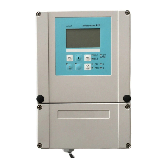
Mycom S CPM 153 2 Identification Identification Instrument designation 2.1.1 Product structure pH/redox transmitter in aluminium housing for wall mounting with one alarm and two output contacts for NAMUR, ChemoClean, and controller functions as well as three binary inputs, logbooks, data logger. Plain text operation. 247x167x111 mm (HxWxD). -
Page 8: Scope Of Delivery
Mycom S CPM 153 2.1.2 Nameplate Fig. 1: Example for a nameplate of the transmitter Mycom S CPM 153. Scope of delivery Check the scope of delivery using your order and the delivery documents for: • Completeness • Instrument type and version acc. to the nameplate (see Chap. 2.1.2) •... -
Page 9: Installation
The original packaging offers the best protection. Also, keep to the approved ambient conditions (see "Technical data"). • If you have any questions, please contact your supplier or your nearest Endress+Hauser sales centre (see the back page of these Operating Instructions). Installation conditions 3.2.1... - Page 10 Mount the parts of the mounting kit (see accompanying figure) at the back of the housing as depicted in Fig. 4. Required mounting cutout: 161 x 241 mm Installation depth: 134 mm Pipe diameter: max. 70 mm Fig. 3: Mounting kit Mycom S CPM 153 Endress+Hauser...
-
Page 11: Checking The Installation
Mycom S CPM 153 3 Installation Fig. 4: Panel mounting and post mounting for CPM 153, horizontal and vertikal " Caution! Danger of instrument damage. For outdoor use, the CYY 101 weather protection cover is required (see Fig. 5 and "Accessories"). -
Page 12: Electrical Connection
4 Electrical connection Mycom S CPM 153 Electrical connection Quick wiring guide 4.1.1 Wiring diagram pH electrode 1 IsFET pH sensor 1 ext. Hold n.c. Ref. Ref. ChemoClean "Clean" Temp. 1 Temp. 1 ChemoClean "User" n.c. 15 V Power supply... - Page 13 4 Electrical connection Warning! A mains disconnecting device must be installed near the instrument and must be identified as the mains disconnection device for the Mycom S CPM 153 (see EN 61010-1). Note! Connect unused signal wires from input and output lines to the internal PE rail of the CPM 153.
- Page 14 Terminal assignment in the lower housing section of the transmitter 4.1.3 Contact assignment In the basic version, the Mycom S CPM 153 possesses 1 alarm and 2 additional contacts. The instrument can be upgraded with the following additional equipment: • 3 contacts •...
-
Page 15: Sensor Connection And Measuring Cable
Mycom S CPM 153 4 Electrical connection Sensor connection and measuring cable 4.2.1 Cable types You require a screened special cable to connect pH and redox electrodes. You can use the following multicore and preterminated cable types: • CPK 1 for electrodes without Pt 100 •... - Page 16 4 Electrical connection Mycom S CPM 153 4.2.2 Changing the pH input from glass electrode to IsFET sensor With this device you can run the electrode types glass electrode / redox electrode or IsFET sensors. For adapt the electrical connection from glass electrodes to IsFET sensor CPS 401, please proceed as follows: Open housing cover of the CPM 153.
- Page 17 Mycom S CPM 153 4 Electrical connection 4.2.4 Cable extension If a cable extension is necessary, use • junction box VBM and the following types of non-terminated measuring cables: • for CPK 1, CPK 9: Cable CYK 71 • for CPK 6: Cable DMK •...
- Page 18 4 Electrical connection Mycom S CPM 153 Symmetrical (with PML) Unsymmetrical (without PML) If the instrument input is unsymmetrical, " Caution! pH measuring chains connected to With a symmetrical connection, the line assemblies can be connected without to the potential matching pin (PML) must an additional potential matching pin.
-
Page 19: Post Connection Check
Mycom S CPM 153 4 Electrical connection Post connection check After wiring up the electrical connection of the measuring instrument, carry out the following checks: Note Instrument status and specifications Is the measuring instrument or the cable damaged externally? Visual inspection... -
Page 20: Operation
13: ENTER key 5.1.2 Key assignment "PARAM" brings you to the Configuration menu of the Mycom S CPM 153. Note! "PARAM" allows you to return to the previous "return field" from any point in the menu. These are marked in bold in the menu overview (see Chap. 11.1). - Page 21 Mycom S CPM 153 5 Operation "MEAS" switches to Operation. This displays the measured values. Use the arrow keys to scroll through the different measuring menus. Note! Press "MEAS" to exit any of the "PARAM", "DIAG", "CAL" menus without terminating the settings / calibration.
- Page 22 5 Operation Mycom S CPM 153 5.1.4 Data logger In the CPM 153, you have two data loggers available. With these data loggers you can • Record a parameter with 500 sequential measuring points or • two parameters each with 250 sequential measuring points.
- Page 23 Mycom S CPM 153 5 Operation Locking the operation This key combination locks the instrument from in-field configuration operations. To lock it, press "CAL" and "DIAG" simultaneously. At the code prompt, the code appears as "9999". Only the settings in the "PARAM" menu can be seen.
-
Page 24: Replaceable Memory
5 Operation Mycom S CPM 153 5.1.7 Factory setting All the factory parameters are active when the instrument is switched on for the first time. The table below lists all the main settings. For all further factory settings, refer to the description of the function groups (from page 31), there the factory setting is printed in bold. -
Page 25: Start-Up
Mycom S CPM 153 6 Start-up Start-up Installation and function inspection Warning! Before power-up, make sure there is no danger to the measuring point. Uncontrolled actuated pumps, valves or similar could lead to damage to instruments. " Caution! • Before switching on, check all the connections again for correctness. -
Page 26: Quick Setup
6 Start-up Mycom S CPM 153 Quick Setup In this menu, configure the most important transmitter functions required for measurement. The Quick Setup ist started automatically when starting the instrument. You can open the Quick Setup at any time from the menu structure. - Page 27 Mycom S CPM 153 6 Start-up CODE DISPLAY CHOICE INFO (default = bold) Dual channel Selection (only two circuit) Hold Redundancy Dual channel: 2 electrodes work comple- Dual 1+2 channel Look-ahead tely independently of each other. Redundancy: Detection of electrode wear.
- Page 28 6 Start-up Mycom S CPM 153 CODE DISPLAY CHOICE INFO (default = bold) Temperature measurement K1 Hold (only for redox) ATC K1 Select temperature compensation K2 Hold ATC K2 (only pH, two circuit) MTC+Temp 025.0°C Temperature value K2 Hold (only for pH, two circuit and selection of MTC or MTC+Temp.
- Page 29 Mycom S CPM 153 6 Start-up CODE DISPLAY CHOICE INFO (default = bold) pH/redox K1 Select current output 1 Hold pH/redox K2 (K2 only for two-circuit) Temperature K1 Selection of the parameter, which shall be Temperature K2 output on the current output.
- Page 30 6 Start-up Mycom S CPM 153 Note! The two-circuit instrument offers you the possiblity of connecting two electrodes which • work completely independently of each other (dual channel) or • Redundancy measurement is always advisable when it is necessary to detect elec- trode wear at an early stage.
-
Page 31: Description Of Functions
Mycom S CPM 153 6 Start-up Description of functions 6.5.1 Set up 1 – Sensor input In this menu, you can change the measured value acquisition settings, such as the operating mode, the measuring principle, or the electrode type. Apart from the measured value attenuation, you have already made all the settings in the menu at the first commissioning in Quick Setup (s. - Page 32 6 Start-up Mycom S CPM 153 CODE CHOICE INFO (default = bold) Dual channel Selection (only two circuit) Redundancy Electrodes measure with: Look-ahead Dual channel: completely independent of each other (you can set the "Delta Alarm" in the alarm menu, s. page 43).
- Page 33 Mycom S CPM 153 6 Start-up 6.5.2 Set up 1 – Display To enter the menu, proceed as follows: ⇒ ⇒ PARAM CODE CHOICE INFO (default = bold) Select language Depending on ordered language version. Language version variants: -A: E / D...
- Page 34 6 Start-up Mycom S CPM 153 6.5.3 Set up 1 – Access codes To enter the menu, proceed as follows: ⇒ ⇒ ⇒ PARAM CODE CHOICE INFO (E1, 2 = editor types, s. page 23) (default = bold) 0000 Enter maintenance code In the range 0000 ...
- Page 35 Mycom S CPM 153 6 Start-up 6.5.4 Set up 1 – Current outputs The transmitter is equipped with two current outputs. To enter the menu, proceed as follows: ⇒ ⇒ PARAM CODE CHOICE INFO (default = bold) Current output 1...
- Page 36 6 Start-up Mycom S CPM 153 CODE CHOICE INFO (default = bold) linear: EAA1 0/4 mA: 02.00 pH Entry of the upper and lower measured value limits / 000.0°C / -0500 mV The maximum measured value range is 20 mA: 12.00 pH –2 ...
- Page 37 Mycom S CPM 153 6 Start-up – Linear delta pH on current output If the current outputs are defined via positive and negative delta values, there is a linear output on the current outputs (see table column 2). Delta pH as value on current output...
- Page 38 6 Start-up Mycom S CPM 153 6.5.5 Set up 1 – Relays To enter the menu, proceed as follows: ⇒ ⇒ PARAM CODE SELECTION INFO (default = bold) NAMUR: Contact functions Relay 1: free Depending on the equipment available, you can assign...
- Page 39 Mycom S CPM 153 6 Start-up CODE SELECTION INFO (default = bold) NC contact Selection acc. to NAMUR: NO contact (only, if NAMUR is activated) Assignment of NAMUR contacts as NC contact (= nor- mally closed contact, opens when relay active) or NO contact (= normally open contact, closes when relay active).
- Page 40 ATC: Automatic temperature compensation: The medium temperature is measured with a temperature sensor. This temperature is used via the temperature input in the Mycom S CPM 153 to adjust the electrode slope to the medium temperature. MTC: Manual temperature compensation: This is advisable in processes which run at a constant temperature.
- Page 41 Mycom S CPM 153 6 Start-up To enter the menu, proceed as follows: ⇒ ⇒ PARAM CODE CHOICE INFO (default = bold) Temperature Selection for temperature compensation Medium compensation Temperature = automatic (ATC) or manual (MTC) temperature compensation. Medium compensation (only for pH) = compensation of the medium using customer-specific tables (see below).
- Page 42 6 Start-up Mycom S CPM 153 CODE CHOICE INFO (default = bold) Medium compensation (only for pH): Select table Selection Create tables Enter / activate customer-specific temperature compen- Reference temperature sation tables. Select table = select for activation Select table:...
- Page 43 Mycom S CPM 153 6 Start-up 6.5.7 Set up 1 – Alarm The CPM 153 continuously monitors the most important functions. If an error occurs, an error message (list of all error messages s. page 93) is set, which can trigger one of the following actions: •...
- Page 44 6 Start-up Mycom S CPM 153 CODE CHOICE INFO (default = bold) E 025 Error/contact assignment Each error can be assigned individually: No.= error number E025 A = Assignment to alarm relay (activating/ deactivating). An activated error triggers an alarm.
- Page 45 Mycom S CPM 153 6 Start-up CODE CHOICE INFO (default = bold) 010 s Enter hold delay time (0 ... 999 s) The hold remains active for the given hold delay time after leaving the CAL, PARAM, DIAG menus. During the hold delay time in the display "Hold"...
- Page 46 6 Start-up Mycom S CPM 153 CODE CHOICE INFO (default = bold) Manual calibration: Enter spec. buffer Calibration parameters Manual buffer Sets the calibration type undertaken when the "CAL" Buffer table key is pressed: Auto. buffer recognition Data entry: Entry of zero point and sensor slope.
- Page 47 Mycom S CPM 153 6 Start-up CODE CHOICE INFO (default = bold) °C: Value pair entry 000.0 04.00 Enter temperature and pH/Redox (number of required 005.0 04.05 value pairs = number of support points desired in field JB3). Selection: Delete element(s)
- Page 48 6 Start-up Mycom S CPM 153 CODE CHOICE INFO (default = bold) Function1/2: Isothermic compensation Activate the isotherm compensation and insert the Uis 1/2: 00.00pH isotherm intersection point (Uis). (0...16pH) Function off: for E+H electrodes ≠ Function on: Only if the isotherm intersection point zero point of the electrode.
- Page 49 Mycom S CPM 153 6 Start-up Operating mode Redox To enter the menu, proceed as follows: ⇒ ⇒ PARAM CODE CHOICE INFO (default = bold) Offset Calibration menu selection Manual calibration Offset: Entry of a fixed value by which the mV value is dis- Cal.
- Page 50 6 Start-up Mycom S CPM 153 CODE CHOICE INFO (default = bold) threshold 02 mV Stability length 010s During calibration the mV values may maximally vary for the given threshold within the defined time range (length). During calibration, the mV value may change during the given period ("duration") at maximum by the stated...
- Page 51 Mycom S CPM 153 6 Start-up 6.5.10 Set up 2 – Data Log The data logger records two freely selectable parameters with their date and time. You can start it using the measuring menus: Use the arrow keys to scroll through the measuring menus until to you reach the Record mode of the data logger.
- Page 52 6 Start-up Mycom S CPM 153 6.5.11 Set up 2 – Check To enter the menu, proceed as follows: ⇒ ⇒ PARAM CODE CHOICE INFO (default = bold) SCS K1: Select SCS (= Sensor Check System) mode for meas- SCS Ref. K1:...
- Page 53 Mycom S CPM 153 6 Start-up 6.5.12 Set up 2 – Controller settings Requirements for controller settings: You have carried out the following settings which are necessary for controller configuration either in the Quick Setup, page 25 or on the appropriate menu page.
- Page 54 6 Start-up Mycom S CPM 153 With active control, the batch and inline processes are different in their relationship to Batch or inline process arrangement: the medium current: Pure batch process: the batch container is filled with the medium. During the subse- quent batch process, no additional medium is fed in.
- Page 55 Mycom S CPM 153 6 Start-up contact contact time [s] time [s] period T Fig. 18: left: pulse-width modulation (PWM) Right: pulse-frequency modulation (PFM) Three PS ("three-point step controller") With the Mycom S, this type of control is only possible for one process side (acid or alkali).
- Page 56 6 Start-up Mycom S CPM 153 This selection is not complete. If you wish to use additional functions such as NAMUR or ChemoClean, please check to see if you require additional relays (NAMUR: Alarm relay + 2 relays; ChemoClean: 2 relays).
- Page 57 Mycom S CPM 153 6 Start-up Selection aid for batch processes Required hardware equipment Process Dosing actuators for control Ordering variants CPM 153- Circuits Relay Current Current inputs outputs – – 1 PWM x1x0xxxxx – – 1 PFM x1x0xxxxx with 1-sided –...
- Page 58 6 Start-up Mycom S CPM 153 K (X) – 1/(T *S) T *S Fig. 20: Schematic diagram of the CPM 153controller with K (X) as the total gain Actual value Set point Control difference Set value Modulation gain (total gain)
- Page 59 Mycom S CPM 153 6 Start-up Kp(X) 100 % X too low X too big ⇒ dosing ⇒ dosing base acid -100 % BaseFull BaseTentative BaseNeutral SetPoint AcidNeutral AcidTentative AcidFull Fig. 22: Diagram to describe the most important corner points for control With this characteristic, a reference set value is prescribed to the controller for each pH value.
- Page 60 6 Start-up Mycom S CPM 153 To enter the menu, proceed as follows: ⇒ ⇒ PARAM CODE CHOICE INFO (default = bold) Selection of Controller settings Note! You must activate the controller settings after you have configured the controller in this menu branch.
- Page 61 Mycom S CPM 153 6 Start-up CODE CHOICE INFO (default = bold) +Relay n.c. Relay selection –Relay n.c. (for three-point step controller) Motor run time +Relay: Open the valve further (= increase dosing) Position feed- –Relay: Close the valve further (= reduce dosing) back (The first free relay is always offered as the default.)
- Page 62 6 Start-up Mycom S CPM 153 CODE CHOICE INFO (default = bold) 1 Output: MBA1 0 ... 20 mA Current output 4 ... 20 mA Selection of the current range, which should be output at current output 2. The neutral position (= current value which the control- ler outputs when it is not dosing) is in the middle of the selected range.
- Page 63 Mycom S CPM 153 6 Start-up CODE CHOICE INFO (default = bold) MBB7 Relay: n.c. Alkali dosing: Relay selection Period: 000.0 s (for pulse length) min: 000.0 s Description see above Sensor technology: Look-ahead measurement: Note in display: pH circuit 1 = controller...
- Page 64 6 Start-up Mycom S CPM 153 CODE CHOICE INFO (default = bold) Function Feedforward control Limit value 050.0 (only if 2 current inputs are available) Kffc=1: 050.0 The feedforward control has a multiplying effect, i.e. Kmax: the controller set value is multiplied with the modulation Kstop: gain Kstör.
- Page 65 Mycom S CPM 153 6 Start-up CODE CHOICE INFO (default = bold) curr. mA value: Assign a value for y = 0% ____ mA Drive the valve to y = 0%. The current current value is displayed. You can change the valve position either manually or by pressing the arrow keys on the transmitter.
- Page 66 6 Start-up Mycom S CPM 153 CODE CHOICE INFO (default = bold) Simulation Selection controller simulation Here, you can switch a configuration loop on or off. The hold is removed with an active controller simulation. Simulation on: The characteristic values entered in the previous field are used in the next field to simulate the controller behaviour.
- Page 67 Mycom S CPM 153 6 Start-up 6.5.13 Set up 2 – Limit switch The Mycom S has several possibilities for assigning a relay contact. The limit switch can be assigned to a switch-on and switch-off point, as well as a pickup and dropout delay.
- Page 68 6 Start-up Mycom S CPM 153 To enter the menu, proceed as follows: ⇒ ⇒ PARAM CODE CHOICE INFO (default = bold) Limit switch 1 Selection Limit switch 2 of the limit switch which you wish to configure. There are Limit switch 3 five limit switches available.
- Page 69 Mycom S CPM 153 6 Start-up 6.5.15 Set up 2 – ChemoClean ® hemoClean is an automatic cleaning system for pH/redox electrodes. The injector (e.g. CYR 10) conveys water and cleaner over two contacts to the electrode. MEAS DIAG PARAM Fig.
- Page 70 6 Start-up Mycom S CPM 153 Weekly programming: "PARAM" "Set up 2" "ChemoClean": Each day can be programmed individually. The following programmes are available • "Clean": Cleaning trigger by entering the start time • "Clean Int": Cleaning is carried out at intervals with a defined spacing. This pro- gramme cannot be started via the binary inputs directly.
- Page 71 Mycom S CPM 153 6 Start-up To enter the menu, proceed as follows: ⇒ ⇒ PARAM CODE CHOICE INFO (default = bold) Weekly progr. Select control levels Clean trigger Select the function which will trigger ChemoClean Ext. Control cleaning. Weekly progr.
- Page 72 6 Start-up Mycom S CPM 153 CODE CHOICE INFO (default = bold) OAA3 0010s Water / cleaner: Enter the time during which the valve remains open to (0 ... 9999s) allow the conveyance of water or cleaner. OAA4 Repeat x number of times...
- Page 73 Mycom S CPM 153 6 Start-up CODE CHOICE INFO (default = bold) Move to: NADA4 (Displays blocks as list) Select rows 01 Water You move the function selected in Field NADA1to the 02 +Cleaner highlighted position. 03 Wait Note! The highlighted position will be overwritten.
- Page 74 6 Start-up Mycom S CPM 153 6.5.16 Manual operation To enter the menu, proceed as follows: ⇒ ⇒ PARAM CODE CHOICE INFO (Default = bold) ChemoClean Select manual operation Hold Note! • Leave the manual operation menu by pressing "PARAM", "DIAG" or "MEAS".
- Page 75 Mycom S CPM 153 6 Start-up 6.5.17 Diagnosis To enter the menu, proceed as follows: ⇒ ⇒ CODE CHOICE INFO (Default = bold) Error list Error list: Displays the current active errors. Error log (Complete error list with description s. page 93)
- Page 76 6 Start-up Mycom S CPM 153 CODE CHOICE INFO (Default = bold) Service data / logbooks: YAA1 0000 Service code entry required Note! For service access code, see Field D1, p. 34. YAA2 Note in display: Incorrect service code entry...
- Page 77 Mycom S CPM 153 6 Start-up CODE CHOICE INFO (Default = bold) DAT handling: Save to DAT DAT selection Read from DAT Save to DAT: You can save the both the configuration Erase DAT and the logbooks of your transmitter to the DAT mod- ule.
- Page 78 6 Start-up Mycom S CPM 153 CODE CHOICE INFO (Default = bold) SW Version: Transmitter 2 data HW Version: Open transmitter data (2). Serial No.: 12345678 Card ID: SW Version: DC-DC converter HW Version: (only for two-circuit)) Serial No.: 12345678...
- Page 79 Mycom S CPM 153 6 Start-up 6.5.18 Calibration Note! The defaults for the on-site calibration are set in the menu "PARAM" "Set up 1" "Calibration" (s. page 80 for pH / page 82 for redox). The calibration can be protected with the maintenance and the specialist codes. No calibration can be carried out at the display level (compare with page 34).
- Page 80 6 Start-up Mycom S CPM 153 To enter the menu, proceed as follows: ⇒ ⇒ "Manual data entry" () pH calibration The numeric values for electrode zero point and slope are entered numerically and by hand. CODE CHOICE INFO (default = bold)
- Page 81 Mycom S CPM 153 6 Start-up CODE CHOICE INFO (default = bold) Electrode 1 Selection for calibration Electrode 2 (only two-circuit) shared Select electrode 1 or 2, and then run through calibra- Abort calibration tion for each individual electrode. Calibration with manual buf-...
- Page 82 6 Start-up Mycom S CPM 153 "Absolute data entry" Calibration redox absolute The transmitter has a calibrated mV display range. One absolute mV value is set with a single buffer solution (adaptation of the measuring chain offset). A buffer solution preferably with 225 or 475 mV is used.
- Page 83 Mycom S CPM 153 6 Start-up "Calibration absolute" Calibration redox absolute The transmitter has a calibrated mV display range. One absolute mV value is set with a single buffer solution (adaptation of the measuring chain offset). A buffer solution preferably with 225 or 475 mV is used.
- Page 84 6 Start-up Mycom S CPM 153 "Absolute data entry" Calibration redox relative The transmitter has a calibrated mV display range. One absolute mV value is set with a single buffer solution (adaptation of the measuring chain offset). A buffer solution preferably with 225 or 475 mV is used.
- Page 85 Mycom S CPM 153 6 Start-up "Calibration absolute" Calibration redox relative The transmitter has a calibrated mV display range. One absolute mV value is set with a single buffer solution (adaptation of the measuring chain offset). A buffer solution preferably with 225 or 475 mV is used.
- Page 86 6 Start-up Mycom S CPM 153 "Data entry relative" Calibration redox relative Entry of two % calibration points to which one mV value is assigned. CODE CHOICE INFO (default = bold) Electrode 1 Selection for calibration Electrode 2 (only two-circuit)
- Page 87 Mycom S CPM 153 6 Start-up "Calibration relative" Calibration redox relative For calibration, two tanks are filled with a sample of the medium. The contents of the first tank are detoxified and are called Buffer 1. The contents of the second tank are left unchanged and are called Buffer 2.
- Page 88 6 Start-up Mycom S CPM 153 "50 % turnover point" Calibration redox relative The 50 % turnover point must be known (e.g. through titration of the toxic solution). It is used as the buffer of a sample at this turnover point.
-
Page 89: Maintenance
Mycom S CPM 153 7 Maintenance Maintenance CPM 153 does not contain wear parts and is maintenance free. Measuring point maintenance comprises: • cleaning the assembly and electrode • inspecting cables and connections, • calibration (see page 83). Warning! Danger to persons. If you have to remove the electrode for servicing or calibration work, pay attention to the hazards caused by pressure, temperature and contamination. - Page 90 7 Maintenance Mycom S CPM 153 7.1.3 Calibration Calibration is necessary: • after electrode replacement • after downtimes (Caution: a pH glass electrode may not be stored in a dry environ- ment.) • At reasonable intervals, dependent on the process. The required interval can range between several times a day to once every three months.
- Page 91 Removing diaphragm blockages: Blocked reference system for reference electrode diaphragms can be mechanically cleaned (does not apply to IsFET pH sensor, teflon diaphragms or open ring electro- des): • Use a small key file. • Only file in one direction. Check for air bubbles in the glass electrode: air bubbles indicate incorrect installation.
-
Page 92: Troubleshooting
8 Troubleshooting Mycom S CPM 153 Troubleshooting Troubleshooting relates not only to measures which • can be carried out without opening the instrument but also to • instrument defects which require the replacement of components. Troubleshooting instructions In this chapter, you will find diagnosis information and information on eliminating errors which occur: Chap. - Page 93 Mycom S CPM 153 8 Troubleshooting 8.1.1 Error number list: Trouble-shooting and configuration In the following error list, you can find a description of all the error numbers occurring. For each error number, you can see whether the error triggers •...
- Page 94 8 Troubleshooting Mycom S CPM 153 Error NAMUR Error message Possible causes / measures Alarm Error Automatic class contact current cleaning start Fact User Fact User Fact User E027 Failure Compressed air fail- Pressure below permitted minimum E 030 Failure...
- Page 95 Mycom S CPM 153 8 Troubleshooting Error NAMUR Error message Possible causes / measures Alarm Error Automatic class contact current cleaning start Fact User Fact User Fact User E027 Failure Compressed air fail- Pressure below permitted minimum E 030 Failure...
- Page 96 8 Troubleshooting Mycom S CPM 153 Error NAMUR Error message Possible causes / measures Alarm Error Automatic class contact current cleaning start Fact User Fact User Fact User E055 Failure Display range of main parameter 1 under- shot E056 Failure...
- Page 97 Mycom S CPM 153 8 Troubleshooting Error NAMUR Error message Possible causes / measures Alarm Error Automatic class contact current cleaning start Fact User Fact User Fact User E073 Failure Temperature 1, table value undershot E074 Failure Temperature 2, table value undershot Check temperature value for plausibility;...
- Page 98 8 Troubleshooting Mycom S CPM 153 Error NAMUR Error message Possible causes / measures Alarm Error Automatic class contact current cleaning start Fact User Fact User Fact User E168 Mainte- SCS message IsFET – nance sensor 1 Leak current > 200 nA. Early warning.
- Page 99 Mycom S CPM 153 8 Troubleshooting 8.1.2 Process-specific errors Error Possible cause Remedial action Equipment needed, spare parts Instrument Instrument hardware is locked via Press "MEAS" and "PARAM" simultane- unconfigurable, keyboard (Keys "CAL" + "DIAG" ously to unlock. Display for code prompt...
- Page 100 8 Troubleshooting Mycom S CPM 153 Error Possible cause Remedial action Equipment needed, spare parts pH value in process No / incorrect temperature compen- ATC: Activate function incorrect sation MTC: Set process temperature Conductivity of medium too low Select pH electrode with salt supply e.
- Page 101 Mycom S CPM 153 8 Troubleshooting Error Possible cause Remedial action Equipment needed, spare parts Feed forward control Additional module M3R-x missing Additional module M3R-2 with 1 or See spare parts list in see Chap. 8.3 does not work M3R-1 with 2 current inputs...
-
Page 102: Response Of Outputs To Errors
8 Troubleshooting Mycom S CPM 153 Error Possible cause Tests and / or remedial Equipment, spare parts, action personnel Incorrect measured pH Transmitter module defective Test measuring inputs: If test negative: Replace module / mV value and / or (module: MKP2), please carry out... -
Page 103: Spare Parts
Mycom S CPM 153 8 Troubleshooting Behaviour with NAMUR setting Instrument status Alarm relay Maintenance Function Limit value/Controller relay check Normal operation Picked-up Appropriate (Fail-safe configuration and behaviour) operating status Failure Dropped out Maintenance required Picked up Function check Picked up... - Page 104 8 Troubleshooting Mycom S CPM 153 Spare parts list Pos. Kit name Contents / Use Order code Terminal module non-Ex Module M3K 51507084 Power supply 100 ... 230 VAC non-Ex Module M3G, power unit + 3 relay 51507087 Power supply 24 VAC/DC non-Ex...
-
Page 105: Installation And Removal Of Parts
Mycom S CPM 153 8 Troubleshooting Installation and removal of parts Please observe the danger instructions in Chap. 8.3. The position designations relate to the spare parts list on page 103. 8.4.1 Device view ƒig. 29: Interior view of the transmitter Mycom S Remarks: A: The figure shows the non-Ex fuse. -
Page 106: Replacing The Device Fuses
If the fuse should fail again, have the device checked. Disposal The Mycom S CPM 153 is a transmitter which contains electronic components and PCBs and therefore must be disposed of as electronic refuse. Please keep to the local regulations. -
Page 107: Accessories
Mycom S CPM 153 9 Accessories Accessories Offline configuration Parawin The Parawin tool provides you with a graphic PC operating program for configuring your measuring point at the PC using a simple and self-explanatory menu structure. Write the configuration to the DAT module using the RS232 interface on the PC. The module can then be plugged into the transmitter. - Page 108 Technical Information TI 046C/07/en, Order No. 50014223 Service adapter The service adapter aids communication between Endress+Hauser transmitters and Optoscope the PC using the service interface. You can use it to load new firmware and to save/write customer data (using a PC with the Windows 95/98 or Windows NT operating system).
- Page 109 Mycom S CPM 153 9 Accessories Measuring cable as yard Cable Description Order number goods Measuring cable, consisting of a coaxial cable and 4 pilot wires 50085333 CYK 71 Measuring cable for Ex applications 50085673 Connecting measuring cable, consisting of 3 coaxial cables...
-
Page 110: Technical Data
10 Technical data Mycom S CPM 153 Technical data 10.1 Input Measured variables pH, redox, temperature pH (glass / IsFET) Measuring range –2.00 ... +16.00 Measured value resolution pH 0.01 Zero point offset range pH –2 ... +16 Range of automatic temperature compensation –50 ... -
Page 111: Output Parameters
Mycom S CPM 153 10 Technical data Digital inputs Input voltage 10 ... 50 V = 5 k Ω Internal resistance : acc. to IEC 746-1, under nominal operating conditions 10.2 Output parameters Output signal pH, redox, temperature Current outputs Current range 0 / 4 ... -
Page 112: Accuracy
10 Technical data Mycom S CPM 153 With the maximum settable frequency in PFM 120 min With the maximum settable period length in PWM 1 ... 999.9 s With PWM minimum switch-on period 0.4 s Relay contacts The NC/NO contact type can be set by software. -
Page 113: Ambient Conditions
Mycom S CPM 153 10 Technical data 10.4 Ambient conditions Ambient temperature –10 ... +55°C Ambient temperature limit –20 ... +60°C Storage and transport –30 ... +80°C temperature Relative humidity 10 ... 95%, non-condensing Ingress protection IP 65 Electromagnetic Interference emission to EN 61326: 1997 / A1:1998; Class B resource (Housing sector) compatibility Interference immunity to EN 61326: 1997 / A1:1998;... - Page 114 10 Technical data Mycom S CPM 153 Endress+Hauser...
-
Page 115: Appendix
Mycom S CPM 153 11 Appendix Appendix 11.1 Operating matrix The basic structure of the operating menu is shown below. PARAM Sensor input Display PARAM Set up 1 Bus configuration Access codes Current output Relays Temperature Alarm Hold Calibration Data log... - Page 116 11 Appendix Mycom S CPM 153 PARAM Set up 1 PARAM Set up 2 Controller values Manual Operation First Set up Select dual input Select electrode Select Editing Damping Select Select operating Select measuring Select electrode (only dual input) type 1...
- Page 117 Mycom S CPM 153 11 Appendix Back to return field Query Info field Info field Table status Current output 1/2 Back to nvalid table return field Delete pair --> back Table active Valid table (then back to --> continue the support points)
- Page 118 11 Appendix Mycom S CPM 153 PARAM Set up 1 PARAM Set up 2 Controller values Manual Operation First Set up Select (Sensor input, Display, Access codes, Current output, Relays, Temperature see above) Select Warning, if Edit alarm delay Delta Alarm...
- Page 119 Mycom S CPM 153 11 Appendix Stability (Calibration) Threshold 02mV Back to (1...10) return field length 010s (10...130) Endress+Hauser...
- Page 120 11 Appendix Mycom S CPM 153 PARAM Set up 1 PARAM Set up 2 Controller values Manual operation Quick Setup Select Select Enter Data logger measuring interval Back to Data logger return field Measuring interval 00000s (0 … 36000s) Data logger1/2...
- Page 121 Mycom S CPM 153 11 Appendix Relay selection Dosing via Current output 2 Pulse length : Current output 2 : Assign Back to 100% acid dosing return field Relay: Rel. 1 0 ... 20 mA Period: 000.0s 4 ... 20 mA 0/4 mA t min: 000.0s...
- Page 122 11 Appendix Mycom S CPM 153 PARAM Set up 1 PARAM Set up 2 Controller values Manual operation Quick Setup Select (Data logger, Check, Controller config. and limit functions see above) Select Status info field Select operation List of weekdays...
- Page 123 Mycom S CPM 153 11 Appendix Set number of repetitions Back to return field (0...10) Display programs Enter number of as list return lines in changed form Back to return field »Return field«: press the PARAM = Code entry required...
- Page 124 11 Appendix Mycom S CPM 153 PARAM Set up 1 PARAM Set up 2 Controller values Manual operation Quick Setup Infofield: Status Selection Cleaning Manual operation Select manual operation Automatic Abort Cleaning trigger off Start Chemoclean Ext. control Select Hold...
- Page 125 Mycom S CPM 153 11 Appendix Selection (only 2-circuit) Electrode 1 Electrode 2 Electrode 1+2 Abort Calibration Sensor mode pH: Data input: Data input: Edit Slope 1 Edit Slope 2 Calibration Note: Window info calibra- tion type Zero point 1...
- Page 126 11 Appendix Mycom S CPM 153 DIAG List of current Select error messages Error list List of errors entered in Error log error log List of last 20 operations Operation log List and status of last 20 Calibration log calibrations...
- Page 127 Mycom S CPM 153 11 Appendix DIAG Select Factory settings, simulation, instrument check, Set up 2 see above) DC DC: Relay: Order code: Controller: Basic module: Transmitter 1/2: Serial number: SW version: ---- SW version: ---- SW version: ---- SW version: ----...
-
Page 131: Buffer Tables
DIN 19267 °C 1,08 1,08 1,09 1,09 1,09 1,09 1,10 1,10 1,10 1,10 1,11 1,11 1,11 1,11 1,11 1,11 1,12 1,12 1,13 1,13 4,67 4,67 4,66 4,66 4,65 4,65 4,65 4,65 4,66 4,67 4,68 4,69 4,70 4,71 4,72 4,73 4,75 4,77 4,79 4,82... - Page 132 Mycom S CPM 153 Index Calibration redox preliminary work ......91 Abnormal transmitter behaviour ....77 Calibration relative (redox rel.).
- Page 133 Mycom S CPM 153 Flow velocity....... 63 flowmeter ....... . . 63 DAT memory module, slot.
- Page 134 Mycom S CPM 153 Maintenance code ......22 PFM ........54 entry .
- Page 135 Mycom S CPM 153 Sensor connection ......15 menu selection ......41 Sensor technology .
- Page 136 Declaration of contamination Dear customer, Because of legal determinations and for the safety of our employes and operating equipment we need this “Declaration of contamination” with your signature before your order can be handled. Please put the completely filled in declaration to the instrument and to the shipping documents in any case. Add also safety sheets and/or specific handling instructions if necessary.
- Page 137 Canada Philippines Poland Minsk ❑ Endress+Hauser Ltd. ❑ Endress+Hauser Philippines Inc. ❑ Endress+Hauser Polska Sp. z o.o. Tel. (0172) 263166, Fax (0172) 263111 Burlington, Ontario Metro Manila Warszawy Tel. (905) 6819292, Fax (905) 6819444 Tel. (2) 3723601-05, Fax (2) 4121944 Belgium / Luxembourg Tel.
Need help?
Do you have a question about the Mycom S CPM 153 and is the answer not in the manual?
Questions and answers