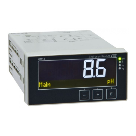
Endress+Hauser Liquiline CM14 Operating Instructions Manual
Four-wire transmitter with memosens input for oxygen content
Hide thumbs
Also See for Liquiline CM14:
- Operating instructions manual (48 pages) ,
- Manual (44 pages) ,
- Operating instructions manual (44 pages)

Related Manuals for Endress+Hauser Liquiline CM14


Summary of Contents for Endress+Hauser Liquiline CM14
- Page 1 Products Solutions Services BA01033C/09/EN/04.22-00 71591816 2022-10-31 Valid as of FW version: 02.01. Operating Instructions Liquiline CM14 Four-wire transmitter with Memosens input for oxygen content...
-
Page 3: Table Of Contents
Liquiline CM14 Table of contents Table of contents Safety instructions ....4 Calibration ..... 22 Workplace safety . -
Page 4: Safety Instructions
Safety instructions Liquiline CM14 Safety instructions Safe operation of the transmitter is only guaranteed if these Operating Instructions have been read and the safety instructions have been observed. Workplace safety When working on and with the device: ‣ Wear the required personal protective equipment as per national regulations. -
Page 5: Technical Improvement
Liquiline CM14 Safety instructions • The manufacturer accepts no liability for damages resulting from incorrect use or use other than that intended. It is not permitted to convert or modify the device in any way. • The device is designed for installation in a panel and must only be operated in an installed state. -
Page 6: Incoming Acceptance And Product Identification
Incoming acceptance and product identification Liquiline CM14 NOTICE Causes (/consequences) Consequences of non-compliance (if applicable) ‣ Protective measure ‣ This symbol alerts you to situations which may result in damage to property. 1.7.2 Document symbols Permitted Indicates procedures, processes or actions that are permitted. -
Page 7: Certificates And Approvals
• Firmware version and device revision 2.2.2 Name and address of manufacturer Name of manufacturer: Endress+Hauser Conducta GmbH+Co. KG Address of manufacturer: Dieselstraße 24, D-70839 Gerlingen Certificates and approvals For certificates and approvals valid for the device: see the data on the nameplate 2.3.1... -
Page 8: Mounting
Mounting Liquiline CM14 Mounting Installation conditions NOTICE Overheating due to buildup of heat in the device ‣ To avoid heat buildup, please always ensure that the device is sufficiently cooled. Operating the display in the upper temperature limit range decreases the operating life of the display. -
Page 9: Post-Installation Check
Liquiline CM14 Electrical connection Screw the threaded rods (item 2) into the positions provided on the mounting frame (item 1). Four opposing screw positions (item 3/4) are available for this purpose. Push the device with the sealing ring through the panel cutout from the front. -
Page 10: Connecting The Transmitter
Electrical connection Liquiline CM14 Energy-rich transients in the case of long signal lines ‣ Connect a suitable overvoltage protection in series upstream. The mixed connection of safety extra-low voltage and dangerous contact voltage to the relay is permitted. Connecting the transmitter A0015215 ... -
Page 11: Post-Connection Check
Liquiline CM14 Operation Terminal Description Terminal for analog output 2, + Terminal for analog output 2, - R11, R12, R13 Terminal for relay 1 R21, R22, R23 Terminal for relay 2 Post-connection check Device condition and specifications Notes Are cables or the device damaged? -
Page 12: Display And Device Status Indicator
Operation Liquiline CM14 Display and device status indicator / LED A0015891 3 Device display Dot matrix section 7-segment display LED status indicator, power supply connected LED status indicator, alarm function LED status indicator, limit switch relay 1/2 Operating keys The device offers users a backlit LC display which is divided into two sections. -
Page 13: Icons
Liquiline CM14 Operation • Open the Configuration menu • Confirm an entry • Select a parameter or submenu offered in the menu Within the Configuration menu: • Gradually scroll through the parameters / menu items / characters offered • Change the value of the selected parameter (increase or decrease) -
Page 14: Operating Functions
Commissioning Liquiline CM14 Reject entry. If this symbol is selected, the entry is rejected and you quit editing mode. The previously set text remains. Jump one position to the left. If this symbol is selected, the cursor jumps one position to the left. -
Page 15: Display Settings (Display Menu)
Liquiline CM14 Commissioning If you are commissioning the device for the first time, program the setup as described in the following sections of the Operating Instructions. If you are commissioning a device that is already configured or preset, the device starts measuring immediately as defined in the settings. -
Page 16: Configuration Of The Device
Commissioning Liquiline CM14 10. Confirm the last position of the code to exit the menu. The full code is displayed. Press + to scroll back to the last item of the x Back submenu and confirm this item. By confirming the point, the value is adopted and the display returns to the Setup level. -
Page 17: Extended Configuration
Liquiline CM14 Commissioning Parameter Possible settings Description Out 1 20 mA Numerical value –0.02 to 120 Physical value which corresponds to the upper 120 mg/l range limit of the analog output. When the configured value is exceeded, the current output is set to the saturation current of 20.5 mA. - Page 18 Commissioning Liquiline CM14 Parameter Possible settings Description Alarm delay 0 to 600 s Delay time for outputting an alarm. This suppresses alarm conditions that are present for a period that is shorter than the alarm delay time. Access code 0000…9999 User code to protect the device configuration.
- Page 19 Liquiline CM14 Commissioning Parameter Possible settings Description Duration 1 to 240 min Duration of the process check 60 min Tolerance 0.01 to 20 hPa Bandwidth for the process check 0.01 hPa Calib. settings This pressure value is used during the calibration for correct calculation.
-
Page 20: Device Diagnostics (Diagnostics Menu)
Commissioning Liquiline CM14 Parameter Possible settings Description Factory default Resets the device settings to the factory default settings. Please confirm no, yes Confirm the reset. 6.5.1 Configuration of the relays The device has two relays with limit values that are either switched off or can be allocated to the input signal. - Page 21 Liquiline CM14 Commissioning Parameter Possible settings Description Order code Displays the order code of the sensor Serial number Displays the serial number of the sensor Device Tag Displays the tag name of the sensor FW version Displays the firmware version...
-
Page 22: Calibration
Calibration Liquiline CM14 Parameter Possible settings Description Alarm out Reset device Reset sensor to factory defaults. Calibration Calibrate the sensor directly after polarization. Remove the sensor from the medium. Clean the outside of the sensor using a damp cloth. Then dry the sensor diaphragm carefully using a paper towel for example. - Page 23 Liquiline CM14 Calibration The (relative) slope characterizes the sensor condition. Decreasing values indicate that the electrolyte is being used up. You can control when the system prompts the user to change the electrolyte by specifying limit values which cause the system to trigger diagnostics messages.
-
Page 24: Device Functions For Calibration
Maintenance Liquiline CM14 Display reads "wait for stable value". When the value is stable, the display changes. Display reads "Zero point" 10. Press "+". Display reads "Save Calib. Data?" 11. Press "+". Display reads "Calib. successful" 12. Press "+". -
Page 25: Accessories
Liquiline CM14 Accessories Accessories Sensors Oxygen sensors Oxymax COS51D • Amperometric sensor for dissolved oxygen, with Memosens technology • Order as per product structure, see Technical Information TI00413C/07/en Diagnostics and troubleshooting To help you troubleshoot, the following section is designed to provide an overview of possible causes of errors and initial remedial measures. - Page 26 Diagnostics and troubleshooting Liquiline CM14 Error category (letter in front of the message number) • F = Failure. A malfunction has been detected. The measured value of the specific channel is no longer reliable. The cause of the malfunction should be sought in the measuring point. If a controller is connected, this should be set to manual mode.
- Page 27 Liquiline CM14 Diagnostics and troubleshooting Error code Message Description Sensor data invalid. Remedy: Sensor data • Update date of the transmitter • Replace sensor The sensor data could not be written. Remedy: Writing data • Repeat writing of the sensor data •...
- Page 28 Diagnostics and troubleshooting Liquiline CM14 Error code Message Description Faulty parameter checksum Possible cause: F846 Param error Firmware update Remedy: Reset parameters to factory defaults F847 Couldn' t save param Parameters could not be saved F848 Calib AO1 Faulty calibration values for analog output 1...
-
Page 29: Firmware History
Liquiline CM14 Diagnostics and troubleshooting Error code Message Description Measured value outside the specified range. Measured value outside the specified range. Possible reasons: • Sensor in air • Air cushion in the assembly S844 Process value • Incorrect sensor inflow •... -
Page 30: Spare Parts
Diagnostics and troubleshooting Liquiline CM14 10.4 Spare parts A0015745 4 Spare parts of the device Item no. Description Order no. Housing front + foil, incl. keyboard CM14, without display XPM0004-DA CPU/Display board CM14 DO amperometric XPM0004-CO Mainboard 24-230VDC/AC, CM14... -
Page 31: Return
Liquiline CM14 Technical data 10.5 Return The device must be packed in protective packaging if it is being returned for repair, for example. The original packaging offers the best protection. Repairs must only be carried out by your supplier' s service organization. -
Page 32: Current Outputs, Active
Technical data Liquiline CM14 11.2.4 Alarm output The alarm output is designed as an "open collector." In normal operation the alarm output is closed. In the event of a fault (F-fault, device without current) the "open collector" opens. Current max. -
Page 33: Wiring
Liquiline CM14 Technical data 11.5 Wiring 11.5.1 Electrical connection Sensor Com B Com A max 30 V 200 mA A0015303 Connection Description Terminal for Memosens cable, brown, sensor power supply U+ Terminal for Memosens cable, white, sensor power supply U-... -
Page 34: Performance Characteristics
Technical data Liquiline CM14 Connection Description Terminal for analog output 1, - Terminal for analog output 2, + Terminal for analog output 2, - R11, R12, R13 Terminal for relay 1 R21, R22, R23 Terminal for relay 2 11.5.2 Supply voltage... -
Page 35: Environment
Liquiline CM14 Technical data Installation position The orientation is determined by the legibility of the display. Max. viewing angle range of +/- 45° from the central display axis in every direction. 92 (3.62) A0010351 5 Panel cutout, dimensions in mm (in) 11.8... -
Page 36: Mechanical Construction
Technical data Liquiline CM14 11.9 Mechanical construction 11.9.1 Dimensions 118.6 (4.67) 16.7 96 (3.78) (0.66) 151.8 (5.98) A0015925 6 Dimensions of the transmitter in mm (in) 11.9.2 Weight 0.3 kg (0.66 lbs) 11.9.3 Materials Housing, casing: Polycarbonate Front foil: Polyester, UV-resistant 11.9.4... -
Page 37: 11.10 Display And Operating Elements
Liquiline CM14 Technical data 11.10 Display and operating elements 11.10.1 Operating elements A0018699 7 Display and operating elements LC display for displaying the measured values and configuration data Status LED, power supply connected Status LED, alarm function Status LED for limit switch relay 1... -
Page 38: Index
Index Liquiline CM14 Index Device configuration Access protection ....15 Diagnostic messages ....25 Display symbols . - Page 40 *71591816* 71591816 www.addresses.endress.com...
Need help?
Do you have a question about the Liquiline CM14 and is the answer not in the manual?
Questions and answers