Endress+Hauser CM14 Operating Instructions Manual
Transmitter, oxygen content
Hide thumbs
Also See for CM14:
- Operating instructions manual (48 pages) ,
- Manual (44 pages) ,
- Operating instructions manual (44 pages)

Related Manuals for Endress+Hauser CM14


Summary of Contents for Endress+Hauser CM14
-
Page 1: Operating Instructions
Products Solutions Services BA01033C/09/EN/02.14 71257167 Valid as of FW version: 02.00.xx Operating Instructions CM14 Transmitter, oxygen content... -
Page 3: Table Of Contents
CM14 Table of contents Table of contents Safety instructions ....4 Device functions for calibration ..24 Workplace safety ....4 Maintenance . -
Page 4: Safety Instructions
Conversions to the device Unauthorized modifications to the device are not permitted and can lead to unforeseeable dangers. ‣ If, despite this, modifications are required, consult with Endress+Hauser. Repair To ensure continued operational safety and reliability, ‣ Carry out repairs on the device only if they are expressly permitted. -
Page 5: Designated Use
If a plastic transmitter housing is permanently exposed to certain steam and air mixtures, this can damage the housing. ‣ If you are unsure, please contact your Endress+Hauser Sales Center for clarification. ‣ If used in an approval-related area, observe the information on the nameplate. - Page 6 Safety instructions CM14 CAUTION Causes (/consequences) Consequences of non-compliance (if applicable) ‣ Corrective action ‣ This symbol alerts you to a dangerous situation. Failure to avoid this situation can result in minor or more serious injuries. NOTICE Causes (/consequences) Consequences of non-compliance (if applicable) ‣...
-
Page 7: Identification
CM14 Identification Identification Device designation 2.1.1 Nameplate Compare the nameplate with the following diagram: Liquiline -10°C (14°F) < Ta < 60°C (140°F) â 1 A0015221 1 Nameplate of the transmitter (example) Device designation Order code, serial number and ID number of the device... -
Page 8: Certificates And Approvals
Identification CM14 Certificates and approvals CE mark, Declaration of Conformity The process display unit is designed to meet state-of-the-art safety requirements, has been tested, and left the factory in a condition in which it is safe to operate. The device complies with the applicable standards and regulations in accordance with EN 61 010-1 "Safety... -
Page 9: Installation
CM14 Installation Installation Incoming acceptance, transport, storage The permitted ambient and storage conditions must be observed. The precise specifications can be found in Section "Technical data" (→ 32). 3.1.1 Incoming acceptance On receipt of the goods, check the following points: •... -
Page 10: Installation Procedure
Installation CM14 Installation procedure The required panel cutout is 92 mm x 45 mm (3.62 in x 1.77 in). A0015216 2 Installation in the panel Screw the threaded rods (item 2) into the positions provided on the mounting frame (item 1). -
Page 11: Wiring
CM14 Wiring Wiring WARNING Danger from electrical voltage ‣ The entire connection of the electrical system must take place while the device is de- energized. Danger if protective ground is interrupted ‣ The protective ground connection must be established before any other connection is made. -
Page 12: Connecting The Transmitter
Wiring CM14 Connecting the transmitter A0015215 3 Connection diagram of the transmitter Terminal Description Terminal for Memosens cable, brown, sensor power supply U+ Terminal for Memosens cable, white, sensor power supply U- Terminal for Memosens cable, green, Com A... -
Page 13: Post-Connection Check
CM14 Wiring Post-connection check Device condition and specifications Notes Are the device or cables damaged? Visual inspection Electrical connection Notes Does the supply voltage match the specifications on the nameplate? 24 to 230 V AC/DC (–20 % / +10 %) 50/60 Hz... -
Page 14: Operation
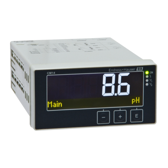
Operation CM14 Operation The easy operating concept of the device makes it possible for users to commission the device for many applications without a printed set of Operating Instructions. Display and device status indicator/LED A0015891 4 Display of the device... -
Page 15: Icons
CM14 Operation • Open the configuration menu • Confirm an entry • Select a parameter or submenu offered in the menu A0010421 Within the configuration menu: • Scroll step-by-step through the parameters/menu items/characters offered • Change the value of the selected parameter (increase or decrease) -
Page 16: Operating Functions
Operation CM14 Move one position to the left. If this icon is selected, the cursor moves one position to the left. Delete back. If this icon is selected, the character to the left of the cursor is deleted. Delete all. -
Page 17: Commissioning
CM14 Commissioning Commissioning Installation check and switching on the device Make sure that all post-connection checks have been carried out before you commission your device: • "Installation check" checklist, (→ 10). • "Post-connection check" checklist, (→ 13). Once the operating voltage is applied, the green LED lights up and the display indicates that the device is operational. -
Page 18: Extended Configuration
Commissioning CM14 The Setup menu includes the most important settings for the function of the device. Parameter Configuration options Description Current range 4-20 mA Configure the measuring range for the current 0-20 mA output. Out 1 0/4 mA Numerical Physical value corresponding to the lower value0.000 to 99 999... - Page 19 CM14 Commissioning Parameter Configuration options Description Alarm delay 0 to 600 s Delay time for issuing an alarm. This suppresses alarm conditions that occur for a period shorter than the alarm delay time. Input Settings of the device Main value Conc.
- Page 20 Commissioning CM14 Parameter Configuration options Description Medium press. Air pressure Use of the altitude or air pressure. Altitude Air pressure 500 to 9 999 mbar Air pressure is set if Medium Press. → Air 1 013 mbar pressure has been selected.
-
Page 21: Device Diagnostics (Diagnostics Menu)
CM14 Commissioning be assigned a channel or calculated value. In "Error" mode, the relay acts as an alarm relay and switches for each error or alarm. The following settings can be made for each of the two limit values: assignment, limit, hysteresis, switching behavior, delay and fault mode. -
Page 22: Calibration
Calibration CM14 Parameter Configuration options Description Sterile counter The system counts the number of operating hours in which the sensor is exposed to a temperature that is typical for a sterilization. This temperature depends on the sensor. Calibration info Calibration data of the last calibration Cal. -
Page 23: Definitions
CM14 Calibration Wait approx. 20 minutes for the sensor to adapt to the temperature of the ambient air. The sensor may not be exposed to harsh sunlight during this time. Once the measured value displayed at the transmitter has stabilized, perform the calibration as described in the Operating Instructions. -
Page 24: Device Functions For Calibration
Calibration CM14 Display reads "Keep sensor above water" Clean and dry the sensor and position it very close to the water. Press "+". Display reads "wait for stable value". When the value is stable, the display changes. Display reads "O2 cal air"... -
Page 25: Maintenance
CM14 Maintenance to open the menu. Select the "x Back" option at the end of each menu/submenu to navigate one level higher in the menu structure. Parameter Configuration options Description Calibration of dissolved oxygen measurement Slope air 100 % Read only... -
Page 26: Accessories
Accessories CM14 Accessories Sensors Oxygen sensors Oxymax COS51D • Amperometric sensor for dissolved oxygen, with Memosens technology • Order as per product structure, see Technical Information TI00413C/07/en Endress+Hauser... -
Page 27: Troubleshooting
CM14 Troubleshooting Troubleshooting The following section provides you with an overview of possible causes of errors to provide you with an initial troubleshooting aid. 10.1 Troubleshooting instructions WARNING Danger from electrical voltage ‣ Do not operate the device for troubleshooting purposes while it is open! - Page 28 Troubleshooting CM14 Sample display: F 61 sensor elec. A0015896 M 915 USP warning A0015897 S 844 Process value A0015898 C 107 Calib. active A0015899 Error code Message Description Sensor data invalid. Remedy: Sensor data • Update date of the transmitter •...
- Page 29 CM14 Troubleshooting Error code Message Description No sensor communication. Possible reasons: • No sensor connection • Faulty sensor connection • Short-circuit in the sensor cable • Short-circuit in the neighboring channel F100 Sensor comm. • Sensor firmware update canceled with an error Remedy: •...
- Page 30 Troubleshooting CM14 Error code Message Description Sensor calibration is active. C107 Calib. active Remedy: Wait for calibration Sensor data. No calibration data present, factory settings will be used. C154 No calib. data Remedy: • Check calibration information of the sensor •...
-
Page 31: Spare Parts
Spare parts A0015745 5 Spare parts of the device Item no. Description Order no. Housing front + foil, incl. keyboard CM14, without display XPM0004-DA CPU/Display board CM14 DO amperometric XPM0004-CO Mainboard 24-230VDC/AC, CM14 XPM0004-NA Relay board + 2 limit relays... -
Page 32: Disposal
Technical data CM14 Please enclose a note describing the fault and the application when sending the unit in for repair. 10.5 Disposal The device contains electronic components and must, therefore, be disposed of as electronic waste in the event of disposal. Please observe in particular the local waste disposal regulations of your country. - Page 33 CM14 Technical data 11.2.4 Alarm output The alarm output is designed as an "open collector." In normal operation the alarm output is closed. In the event of a fault (F-fault, device without current) the "open collector" opens. Current max. 200 mA Voltage max.
-
Page 34: Electrical Connection
Technical data CM14 11.5 Wiring 11.5.1 Electrical connection Sensor Com B Com A max 30 V 200 mA A0015303 Connection Description Terminal for Memosens cable, brown, sensor power supply U+ Terminal for Memosens cable, white, sensor power supply U- Terminal for Memosens cable, green, Com A... - Page 35 CM14 Technical data Connection Description Terminal for analog output 1, - Terminal for analog output 2, + Terminal for analog output 2, - R11, R12, R13 Terminal for relay 1 R21, R22, R23 Terminal for relay 2 11.5.2 Supply voltage...
- Page 36 Technical data CM14 Orientation The orientation is only determined by the legibility of the display. Max. viewing angle +/- 45° in every direction from the central axis of the display. 92 (3.62) A0010351 6 Panel cutout, dimensions in mm (in) 11.8...
- Page 37 CM14 Technical data 11.9 Mechanical construction 11.9.1 Dimensions 118.6 (4.67) 16.7 96 (3.78) (0.66) 151.8 (5.98) A0015925 7 Dimensions of the transmitter in mm (in) 11.9.2 Weight 0.3 kg (0.66 lbs) 11.9.3 Materials Housing, casing: Polycarbonate Front membrane: Polyester, UV-resistant 11.9.4...
-
Page 38: Operating Elements
Technical data CM14 11.10 Display and operating elements 11.10.1 Operating elements A0018699 8 Display and operating elements LC display for measured values and configuration data Status LED power supply connected Status LED alarm function Status LED limit function relay 1... - Page 39 CM14 Technical data Other standards and guidelines • IEC 60529: Degree of protection by housing (IP code) • IEC 61010-1: 2001 Cor 2003 Safety requirements for electrical equipment for measurement, control and laboratory use Endress+Hauser...
-
Page 40: Index
Index CM14 Index Diagnostic messages ....27 Display icons ....15 Error messages . - Page 44 www.addresses.endress.com...
Need help?
Do you have a question about the CM14 and is the answer not in the manual?
Questions and answers