Endress+Hauser Liquiline CM442R Operating Instructions Manual
Universal four-wire multichannel controller for cabinet installation
Hide thumbs
Also See for Liquiline CM442R:
- Operating instructions manual (172 pages) ,
- Technical information (52 pages) ,
- Brief operating instructions (40 pages)
Table of Contents

Related Manuals for Endress+Hauser Liquiline CM442R


Summary of Contents for Endress+Hauser Liquiline CM442R
- Page 1 Products Solutions Services BA01225C/07/EN/01.13 71220430 Valid as of: Softwareversion 01.04.00 Operating Instructions Liquiline CM442R/CM444R/CM448R Universal four-wire multichannel controller for cabinet installation Commissioning...
-
Page 3: Table Of Contents
Liquiline CM442R/CM444R/CM448R Table of contents Document information ..4 Operation options ..40 Warnings ......4 Overview . -
Page 4: Document Information
Document information Liquiline CM442R/CM444R/CM448R Document information Warnings The structure, signal words and color coding of the warnings follow the specifications of ANSI Z535.6 ("Product safety information in product manuals, instructions and other collateral materials"). Structure of the safety Meaning symbol This symbol alerts you to a dangerous situation. -
Page 5: Documentation
Liquiline CM442R/CM444R/CM448R Document information Documentation The Operating Instructions are split into several parts: Commissioning (BA01225C) • All steps that you have to carry out once only during initial commissioning • Descriptions of menus – General settings – Display/operation • Technical data Operation &... -
Page 6: Basic Safety Instructions
Basic safety instructions Liquiline CM442R/CM444R/CM448R Basic safety instructions Requirements for personnel ‣ Installation, commissioning, operation and maintenance of the measuring system must only be carried out by trained technical personnel. ‣ The technical personnel must be authorized to perform the tasks by the owner-operator. -
Page 7: Occupational Safety
Liquiline CM442R/CM444R/CM448R Basic safety instructions 2.2.3 Installation environment The device and associated power units can be operated with 24 V AC, 24 V DC or 100 to 230 V AC and provide shock protection as per the IP20 rating. The components have been designed for Pollution Degree 2. -
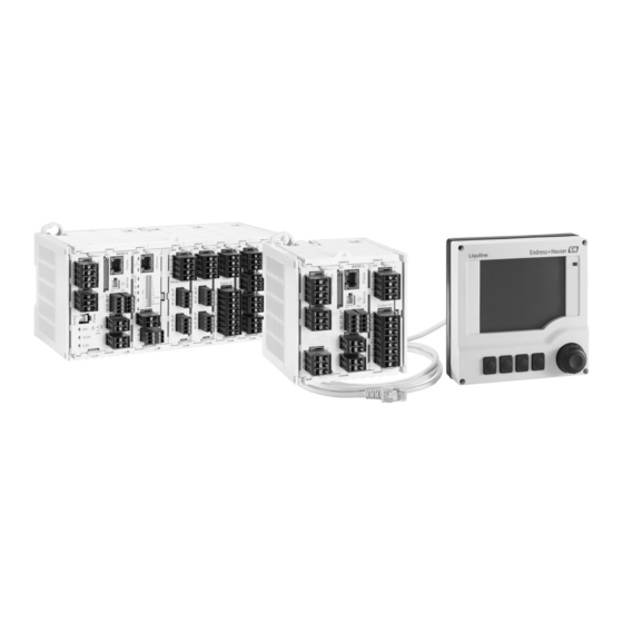
Page 8: Device Description
Device description Liquiline CM442R/CM444R/CM448R Device description Overview a0020573 Fig. 1: CM44xR with optional, external display (excluding cable) CM448R External display (optional) Extension modules (optional) Basic module Shock protection, dummy module CM442R Terminal strip External power unit (only CM444R or CM448R) -
Page 9: Device Architecture
Liquiline CM442R/CM444R/CM448R Device description Device architecture 3.2.1 Slot and port assignment a0019832 a0019833 Fig. 2: Slot and port assignment of the hardware modules • Inputs are assigned to measuring channels in the ascending order of the slots and ports. Adjacent example: "CH1: 1:1 pH glass"... - Page 10 Device description Liquiline CM442R/CM444R/CM448R 3.2.2 Terminal diagram The unique terminal name is derived from the following: Slot No. : Port No. : Terminal Example, NO contact of a relay: Device with 4 inputs for digital sensors, 4 current outputs and 4 relays •...
-
Page 11: Incoming Acceptance And Product Identification
Liquiline CM442R/CM444R/CM448R Incoming acceptance and product identification Incoming acceptance and product identification Incoming acceptance 1. Make sure the packaging is not damaged. Inform your supplier of any damage to the packaging. Please keep the damaged packaging until any issues have been resolved. -
Page 12: Scope Of Delivery
Incoming acceptance and product identification Liquiline CM442R/CM444R/CM448R 4.2.2 Identifying the product The order code and serial number of your device can be found in the following locations: • On the nameplate • On the front page of these Operating Instructions •... -
Page 13: Installation
Liquiline CM442R/CM444R/CM448R Installation Installation Installation conditions 5.1.1 DIN rail mounting CAUTION Power unit can become very hot at maximum load Risk of burns ‣ Avoid touching the power unit during operation. ‣ Make sure to maintain the minimum distances to other devices. - Page 14 Installation Liquiline CM442R/CM444R/CM448R a0020564 Fig. 5: Minimum spacing 5.1.2 Cable length Between power unit and CM44xR: Max. 1 m (3.3 ft) Display cable: Max. 5 m (16 ft) 5.1.3 Wall mounting Via lugs and open slotted holes on the housing a0020541 Fig.
- Page 15 Liquiline CM442R/CM444R/CM448R Installation 5.1.4 External display The mounting plate also acts as the drilling template. The marks at the side help you mark out the position for the drill holes. a0019718 Fig. 7: Mounting plate of the external display Holding clip...
-
Page 16: Mounting The Measuring Device
Installation Liquiline CM442R/CM444R/CM448R Mounting the measuring device 5.2.1 DIN rail mounting Mounting is the same for all the devices. CM448R is shown in the example. When the device is delivered, the retainer slides to secure the DIN rail are "tightened". - Page 17 Liquiline CM442R/CM444R/CM448R Installation 5.2.2 Wall mounting Mounting material (screws, wall plugs) are not included in the delivery and must be provided by the client. CM444R and CM448R: The external power unit can only be mounted on a DIN rail. Use the back of the housing to mark the drill holes for mounting (→ å 6).
- Page 18 Installation Liquiline CM442R/CM444R/CM448R a0019871 a0019872 a0019873 a0019874 a0019903 a0019881 Endress+Hauser...
-
Page 19: Post-Installation Check
Liquiline CM442R/CM444R/CM448R Installation NOTICE Installation errors Damage to cable, for instance, or malfunctions ‣ Route cables in such a way that they cannot be squashed in any way, e.g. when the cabinet door is closed. ‣ Make sure that the display cable is actually plugged... -
Page 20: Electrical Connection
Electrical connection Liquiline CM442R/CM444R/CM448R Electrical connection WARNING The device is live! Incorrect wiring can result in injury or fatality ‣ The electrical connection may only be established by an electrical technician. ‣ The electrical technician must have read and understood these Operating Instructions and must follow the instructions they contain. - Page 21 Liquiline CM442R/CM444R/CM448R Electrical connection 6.1.2 Remote operation via PROFIBUS DP Master class 1 (PLC, DCS) Master class 2 (FieldCare, PDM) PROFIBUS DP (RS485) CM442R/ CM442/ FXA291 CM444R/ CM444/ CM448R CM448 CSF48 CA80 FieldCare / Webbrowser Ethernet a0015874 Fig. 10: PROFIBUS DP...
- Page 22 Electrical connection Liquiline CM442R/CM444R/CM448R 6.1.3 Remote operation via Modbus RS485 Modbus Master / Gateway Modbus RS485 (RTU, ASCII) CM442 / CM442R/ FXA291 CM444 / CM444R/ CM448 CM448R CSF48 CA80 FieldCare / Webbrowser Ethernet a0015875 Fig. 11: Modbus RS485 Terminating resistor 6.1.4 Remote operation via ethernet/Web server/Modbus TCP...
-
Page 23: Connecting The Measuring Device
Liquiline CM442R/CM444R/CM448R Electrical connection Connecting the measuring device WARNING The device is live! Incorrect wiring can result in injury or fatality ‣ Prior to beginning any wiring work, make sure voltage is not applied to any of the cables. NOTICE The device does not have a power switch ‣... - Page 24 Electrical connection Liquiline CM442R/CM444R/CM448R All other plug-in terminals a0012694 a0012695 a0012696 Fig. 16: Insert the screwdriver until the Fig. 17: Insert the cable until the limit Fig. 18: Remove the screwdriver (closes limit stop (opens the terminal) stop the terminal) 6.2.2 Power supply for CM442R...
- Page 25 Liquiline CM442R/CM444R/CM448R Electrical connection NOTICE Incorrect connection and cables not routed separately Interference on signal or display cables, incorrect measured values or display failure possible ‣ Do not connect the cable shield of the display cable to PE (terminal strip of the device)! ‣...
-
Page 26: Connecting The Sensors
Electrical connection Liquiline CM442R/CM444R/CM448R NOTICE Incorrect connection and cables not routed separately Interference on signal or display cables, incorrect measured values or display failure possible ‣ Do not connect the cable shield of the display cable to PE (terminal strip of the device)! ‣... - Page 27 Liquiline CM442R/CM444R/CM448R Electrical connection 6.3.2 Functional ground connection You must always connect the terminal strip with PE of the central star point of the cabinet. Use the wire with cable clamp provided with the Memosens cable to connect the functional ground to the terminal strip of CM44xR.
- Page 28 Electrical connection Liquiline CM442R/CM444R/CM448R a0012459 a0012460 Fig. 24: Sensors without additional supply voltage Fig. 25: Sensors with additional supply voltage a0016197 Fig. 26: Sensors with and without additional supply voltage at sensor module 2DS Endress+Hauser...
-
Page 29: Connecting Additional Inputs, Outputs Or
Liquiline CM442R/CM444R/CM448R Electrical connection Connecting additional inputs, outputs or relays WARNING Module not covered No shock protection. Danger of electric shock! ‣ If you are modifying or extending your hardware, always fill the slots from left to right. Do not leave any gaps. - Page 30 Electrical connection Liquiline CM442R/CM444R/CM448R Example: Chlorine regulation, dosing stopped in the absence of flow a0020123 Fig. 29: Example for chlorine regulation with feedforward control The inductive proximity switch INS of the assembly CCA250 is connected to the digital input of the DIO module to...
- Page 31 Liquiline CM442R/CM444R/CM448R Electrical connection Chlorine regulation with feedforward control Take advantage of the benefits offered by virtually wear-free control with binary outputs compared to a relay-based control system. With pulse-frequency modulation (PFM), it is possible to achieve virtually continuous dosage with a dosing pump with higher input frequencies.
- Page 32 Electrical connection Liquiline CM442R/CM444R/CM448R Example: CM44x as "cleaning master" a0020124 Fig. 30: Example for central cleaning control External cleaning trigger at the binary input Transmission of the external hold via the binary output to other measuring devices without connected cleaning units Transmission of the cleaning trigger via the binary output to other measuring points with their own cleaning units CM44xR as "cleaning master"...
- Page 33 Liquiline CM442R/CM444R/CM448R Electrical connection 6.4.2 Current inputs Module 2AI a0016184 a0015761 Fig. 31: Module front Fig. 32: Wiring diagram 6.4.3 Current outputs Module 2AO Module 4AO a0016179 a0015759 a0016178 a0015760 Fig. 33: Module front Fig. 34: Wiring diagram Fig. 35: Module front Fig.
- Page 34 Electrical connection Liquiline CM442R/CM444R/CM448R 6.4.4 Relays Module 2R Module 4R a0016181 a0015758 a0016182 a0015757 Fig. 37: Module front Fig. 38: Wiring diagram Fig. 39: Module front Fig. 40: Wiring diagram Example: Connecting the cleaning unit 71072583 for CAS40D a0016195 Fig. 41: Connecting the cleaning unit for CAS40D...
- Page 35 Liquiline CM442R/CM444R/CM448R Electrical connection Example: Connecting the injector cleaning unit Chemoclean CYR10 a0016194 Fig. 42: Connecting the injector cleaning unit CYR10 External power supply Cleaner to spray head Container with cleaner Motive water 2 to 12 bar (30 to 180 psi)
-
Page 36: Connecting Digital Communication
Electrical connection Liquiline CM442R/CM444R/CM448R Connecting digital communication 6.5.1 Module 485 a0016173 a0015762 Fig. 43: Bus connections on module 485 Fig. 44: Wiring diagram for module 485 Optional to supply power to an external terminating resistor for bus termination LEDs on front of module... - Page 37 Liquiline CM442R/CM444R/CM448R Electrical connection DIP switches on front of module Factory setting Assignment 1-128 Bus address (--> "Commissioning/Communication") Write protection: "ON" = configuration not possible via the bus, only via local operation Service Only for service, not to be used by the operator 6.5.2 Bus termination...
-
Page 38: Hardware Settings
Electrical connection Liquiline CM442R/CM444R/CM448R External terminating resistor Here, leave the DIP switches on the module board in the "OFF" position (factory setting). ‣ Connect the resistor to terminals 81 and 82 on the front of module 485 for 5-V power supply. -
Page 39: Guaranteeing The Degree Of Protection
Liquiline CM442R/CM444R/CM448R Electrical connection Guaranteeing the degree of protection Only the mechanical and electrical connections that are described in this manual, and are necessary for the required, designated application, may be established on the device supplied. ‣ Please play close attention when performing the work as degrees of protection individually... -
Page 40: Operation Options
Operation options Liquiline CM442R/CM444R/CM448R Operation options Overview 7.1.1 Display and operating elements (only with optional display) a0020580 Fig. 50: Overview of operation Display (lit red in the event of an error) Navigator (jog/shuttle and press/hold function) Soft keys (function depends on the menu) 7.1.2 Display... - Page 41 Liquiline CM442R/CM444R/CM448R Operation options Access to the operating menu via the local display 7.2.1 Operating concept (with optional display) a0013353-en a0013354-en Fig. 52: Pressing the soft key: selecting the menu directly Fig. 53: Turning the navigator: moving the cursor in the...
-
Page 42: Configuration Options
Operation options Liquiline CM442R/CM444R/CM448R 7.2.2 Locking or unlocking operating keys Locking operating keys 1. Press the navigator for longer than 2 s. A context menu for locking the operating keys is displayed. You have the choice of locking the keys with or without password protection. "With password"... - Page 43 Liquiline CM442R/CM444R/CM448R Operation options 7.3.3 Numerical values • You change a variable. • The maximum and minimum values for this variable are shown on the display. • Set a value within this range. • Example: Menu/Display/Operation/Contrast 7.3.4 Actions • You trigger an action with the appropriate function.
- Page 44 Operation options Liquiline CM442R/CM444R/CM448R 7.3.6 Tables • Tables are needed to map mathematical functions. • You edit a table by navigating through rows and columns with the navigator and changing the values of the cells. • You only edit the numerical values. The controller automatically takes care of the engineering units.
-
Page 45: Commissioning
Liquiline CM442R/CM444R/CM448R Commissioning Commissioning Function check WARNING Incorrect connection, incorrect supply voltage Safety risks for staff and incorrect operation of the device ‣ Check that all connections have been established correctly in accordance with the wiring diagram. ‣ Make sure that the supply voltage matches the voltage indicated on the nameplate. - Page 46 Commissioning Liquiline CM442R/CM444R/CM448R Path: Menu/Display/Operation Function Options Info Screen rotation Options If "Automatic" is selected, the single-channel measured • Manual value display switches from one channel to the next • Automatic every second. Factory setting Manual User definable screens Meas. screen 1 You can create 6 measuring screens of your own and give them a name.
-
Page 47: Basic Setup
Liquiline CM442R/CM444R/CM448R Commissioning Path: Menu/Display/Operation Function Options Info Measured value Options Different measured values can be displayed depending • Depends on the data on the source of data or the output. source or output Factory setting None Label Customized text, 20... -
Page 48: Display
Commissioning Liquiline CM442R/CM444R/CM448R Menu in Basic setup Section in BA00450C Software path in main menu Current outputx:y Outputs Setup/Outputs/Current output x:y Limit switches Additional functions Setup/Additional functions/Limit switches Diagnostics settings General settings Setup/General settings/Extended setup/Diagnostics settings Cleaning Additional functions Setup/Additional functions/Cleaning Display 8.4.1 Soft keys in measuring mode... - Page 49 Liquiline CM442R/CM444R/CM448R Commissioning Sensor type Main value Primary / secondary value All values Conductivity, Conductivity Conductivity, temperature Main value, Raw value, Temperature measured conductively Oxygen, Dissolved oxygen Dissolved oxygen, Partial pressure, Saturation, optical and temperature Concentration, Temperature amperometric Chlorine, Chlorine...
- Page 50 Commissioning Liquiline CM442R/CM444R/CM448R Icon Location Description At measured value Automatic temperature compensation active At measured value Manual temperature compensation active Title bar Simulation mode active or Memocheck SIM connected At measured value The measured value is influenced by a simulated value...
-
Page 51: Technical Data
Liquiline CM442R/CM444R/CM448R Technical data Technical data Input 9.1.1 Measured variables --> Documentation of the connected sensor 9.1.2 Measuring ranges --> Documentation of the connected sensor 9.1.3 Types of input • Digital sensor inputs for sensors with Memosens protocol • Analog current inputs (optional) •... -
Page 52: Current Input, Passive
Technical data Liquiline CM442R/CM444R/CM448R 9.2.3 Nominal input current Max. 8 mA 9.2.4 PFM function Minimum pulse width: 500 μs (1 kHz) 9.2.5 Testing voltage 500 V 9.2.6 Cable specification Max. 2.5 mm (14 AWG) Current input, passive 9.3.1 Span > 0 to 20 mA 9.3.2 Signal characteristic... - Page 53 Liquiline CM442R/CM444R/CM448R Technical data HART Signal encoding FSK ± 0.5 mA via current signal Data transmission rate 1200 Baud Galvanic isolation Load (communication resistor) 250 Ω PROFIBUS DP Signal encoding EIA/TIA-485, PROFIBUS-DP-compliant as per IEC 61158 Data transmission rate 9.6 kBd, 19.2 kBd, 45.45kBd, 93.75 kBd, 187.5 kBd, 500 kBd, 1.5 MBd,...
-
Page 54: Digital Outputs, Passive
Technical data Liquiline CM442R/CM444R/CM448R 9.4.2 Signal on alarm Adjustable, as per NAMUR Recommendation NE 43 • In the measuring range 0 to 20 mA (HART is not available with this measuring range): Error current from 0 to 23 mA • In the measuring range 4 to 20 mA: Error current from 2.4 to 23 mA... -
Page 55: Current Outputs, Active
Liquiline CM442R/CM444R/CM448R Technical data Current outputs, active 9.6.1 Span 0 to 23 mA 2.4 to 23 mA for HART communication 9.6.2 Signal characteristic Linear 9.6.3 Electrical specification Output voltage Max. 24 V Testing voltage 500 V 9.6.4 Cable specification Cable type... - Page 56 Technical data Liquiline CM442R/CM444R/CM448R 9.7.2 Relay switching capacity Basic module (Alarm relay) Switching voltage Load (max.) Switching cycles (min.) 230 V AC, cosφ = 0.8 to 1 0.1 A 700,000 0.5 A 450,000 115 V AC, cosφ = 0.8 to 1 0.1 A...
-
Page 57: Protocol-Specific Data
Liquiline CM442R/CM444R/CM448R Technical data Protocol-specific data 9.8.1 HART Manufacturer ID Device type 119C (CM44x), 119D (CSFxx) Device revision HART version Device description files (DD/DTM) www.endress.com Device Integration Manager (DIM) Device variables 16 user-definable and 16 predefined, dynamic variables PV, SV, TV, QV... - Page 58 Technical data Liquiline CM442R/CM444R/CM448R 9.8.3 Modbus RS485 Protocol RTU / ASCII Function codes 03, 04, 06, 08, 16, 23 Broadcast supported for function codes 06, 16, 23 Output data 16 measured values (value, unit, status), 8 digital values (value, status)
-
Page 59: Power Supply
Liquiline CM442R/CM444R/CM448R Technical data Power supply 9.9.1 Supply voltage CM442R Depending on the version: 100 to 230 V AC ± 15%, 50/60 Hz 24 V AC/DC +20 / -15 %, 50/60 Hz CM444R and CM448R Via external DIN rail power unit depending on version: 100 to 230 V AC ±... -
Page 60: 9.10 Performance Characteristics
Technical data Liquiline CM442R/CM444R/CM448R 9.10 Performance characteristics 9.10.1 Response time Current outputs = max. 500 ms for an increase from 0 to 20 mA Current inputs = max. 330 ms for an increase from 0 to 20 mA Digital inputs and outputs = max. -
Page 61: 9.11 Environment
Liquiline CM442R/CM444R/CM448R Technical data 9.11 Environment 9.11.1 Ambient temperature range CM442R 0 to 60 ˚C (32 to 140 ˚F) CM444R • Generally 0 to 55 ˚C (32 to 130 ˚F), with the exception of packages under the second point in the list •... - Page 62 Technical data Liquiline CM442R/CM444R/CM448R 9.11.4 Degree of protection IP 66, at front, when installed correctly and using appropriate protective enclosure 9.11.5 Climate class As per 60654-1: B2 9.11.6 Vibration resistance Environmental tests Vibration test based on DIN EN 60068-2, October 2008...
-
Page 63: 9.12 Mechanical Construction
Liquiline CM442R/CM444R/CM448R Technical data 9.12 Mechanical construction 9.12.1 Dimensions --> "Mounting" section 9.12.2 Weight Depending on the version CM442R (fully assembled) Approx. 0.45 kg (1 lbs) CM444R and CM448R (fully assembled) Approx. 0.95 kg (2.1 lbs) Individual module Approx. 0.06 kg (0.13 lbs) External display (excluding cable) Approx. -
Page 64: Index
Liquiline CM442R/CM444R/CM448R Index Current input Connection ......33 Approvals ......12 Technical data . - Page 65 Liquiline CM442R/CM444R/CM448R Environment Ambient temperature range ... . 61 LEDs ....... . 36 Climate class.
- Page 66 Liquiline CM442R/CM444R/CM448R HART ......20 Modbus ......22 Occupational safety .
- Page 67 Liquiline CM442R/CM444R/CM448R Warnings ......4 Web server Quick wiring guide ....22 Weight .
- Page 68 www.addresses.endress.com...
Need help?
Do you have a question about the Liquiline CM442R and is the answer not in the manual?
Questions and answers