HEIDENHAIN iTNC 530 Service Manual
Hide thumbs
Also See for iTNC 530:
- User manual (745 pages) ,
- Service manual (696 pages) ,
- Technical manual (624 pages)
Table of Contents
Advertisement
Quick Links
Advertisement
Table of Contents
Troubleshooting

Subscribe to Our Youtube Channel
Related Manuals for HEIDENHAIN iTNC 530


Summary of Contents for HEIDENHAIN iTNC 530
- Page 1 Service Manual iTNC 530 May 2006...
-
Page 3: Table Of Contents
5.1 Introduction ........................23 5.2 Notes and Tips....................... 23 5.3 Overview of Possible Errors ..................26 5.4 Important Notes on the Use of HEIDENHAIN Interface Boards in SIMODRIVE System........29 6 Log............................35 6.1 General .......................... 35 6.2 Calling the Log....................... 36 6.3 Overview of Log Entries.................... - Page 4 10.7.2 Analog Inputs ....................107 10.7.3 Inputs for Thermistors ..................107 10.7.4 PLC Outputs ....................108 11 Principle of Operation of the iTNC 530 Control ............109 11.1 Introduction ....................... 109 11.2 Block Diagrams with Short Explanations..............109 11.3 Basic Circuit Diagrams ...................
- Page 5 14.6.3 Supply Voltage for PLC Outputs on the PL 4xx B ..........225 14.6.4 Supply Voltage for PLC Outputs on the PL 510 ..........228 15 Hard Disk and File Manager of the iTNC 530..............231 15.1 Introduction ....................... 231 15.2 Structure of the Hard Disk..................
- Page 6 20.1.4 Trouble Shooting: Exchanging PWM Outputs on the CC 424 ......333 20.1.5 Trouble Shooting: Exchanging Power Modules or Output Stages of the Same Type ...................... 337 20.1.6 Trouble Shooting: Exchanging the HEIDENHAIN Interface Boards for the SIMODRIVE 611 System ................340 20.2 Analog Drives ......................341 20.2.1 Introduction .....................
- Page 7 26.4 Exchanging the MC 422 B or the MC 420..............431 26.5 Exchanging the HDR ....................433 26.6 Exchanging the CC ....................441 26.7 Exchange of Further HEIDENHAIN Components............442 27 Loading of Service Packs ....................443 27.1 Introduction ....................... 443 27.2 Preparations and Execution up to NC Software 34049x-01...
- Page 8 30.2 The Machine Parameter Editor.................. 465 30.3 Meaning of the Machine Parameters ................ 473 30.4 List of Machine Parameters (excerpt from the Technical Manual of iTNC 530 of November 2005) ....... 474 30.4.1 Encoders and Machines .................. 474 30.4.2 Positioning ....................... 480 30.4.3 Operation with velocity feedforward control ...........
-
Page 9: Safety Precautions
Note the safety precautions on the machine (e.g., stickers, signs) and the safety precautions in the documentation of the machine manufacturer (e.g., operating instruction). Caution HEIDENHAIN does not accept any responsibility for indirect or direct damage caused to persons or property through incorrect use or operation of the machine! DANGER... - Page 10 Caution Failure to comply with this information could result in injuries and interruptions of operation up to material damage. Note These boxes contain important and useful information for servicing. 1 – 10 HEIDENHAIN Service Manual iTNC 530...
-
Page 11: Using The Service Manual
Only genuine spare parts are used! Note Basic knowledge in Windows is required for some descriptions in this Service Manual concerning the handling of the dual-processor control iTNC 530 and the use of a service laptop or PC. Udpate service This Service Manual is updated only at irregular intervals. -
Page 12: Other Documentation
Service Training Seminars HEIDENHAIN Traunreut offers service training seminars in German. We recommend the HEIDENHAIN Service Training Seminars for iTNC 530 for the technician who works with this Service Manual. Please inquire at HEIDENHAIN Traunreut or go to our website at www.heidenhain.de/Services/Training. -
Page 13: Code Numbers
Code Numbers Introduction With code numbers … Certain areas of the hard disk Certain file types Certain functions ... can be called. DANGER Code numbers may only be passed on and/or used by trained service technicians. Inexpert handling may result in the loss of important data, in a faulty machine performance and thus lead to damage or injury to property or persons. -
Page 14: Notes On Entering The Code Numbers
Note The machine manufacturer can define own MP and PLC code numbers. In this case the HEIDENHAIN code numbers do not function any longer. --> Contact your machine manufacturer. As long as the machine parameter list is in the editor no further code number can be entered. - Page 15 After you have entered the PLC code number, all files of the PLC tree can be seen and loaded into the editor. However, to edit machine parameters, the soft key MP EDIT needs to be pressed. When you have finished your work do not forget to delete all code-number soft keys (MP EDIT, PLC EDIT, OSCI, etc.) -->...
- Page 16 3 – 16 HEIDENHAIN Service Manual iTNC 530...
-
Page 17: Error Messages
HEIDENHAIN defines how the control reacts to an NC error message (NC stop, EMERGENCY STOP, etc.). HEIDENHAIN defines whether the control can still be operated or has to be rebooted after an NC error message. If you have any questions, please contact your machine manufacturer and/or HEIDENHAIN. - Page 18 EMERGENCY STOP Axes and spindle decelerate at the current limit; the machine should be stopped as fast as possible. The contour of the workpiece is not regarded and may be damaged. 4 – 18 HEIDENHAIN Service Manual iTNC 530...
-
Page 19: Help Key
HELP Key Display help texts for error messages (if this key is pressed again, the window will be closed) If the service technician presses the HELP key a window is shown that describes the cause of error and possibilities of corrective action in addition to the displayed error message. This support can also be realized for PLC error messages by the machine manufacturer! Note HELP texts cannot be displayed any more for error messages in red windows. -
Page 20: Err Key
If there is no ERR key over the HELP key on your keyboard, press the corresponding space bar over the HELP key. --> If the NC software of the iTNC 530 supports the function of the ERR key, the ERR list can also be called! 4 –... -
Page 21: Ce Key
The ERR window is described below: Column Description Number Error number that was defined by HEIDENHAIN or the machine manufacturer (-1: No error number defined) Class Error class. Defines the reaction of the control: ERROR Program run is interrupted by the TNC (INTERNER STOP) -
Page 22: List Of Nc Error Messages
You can find the complete list of NC error messages (incl. operation errors) on the DVD TNCguide in several languages and sorted by error numbers. These TNCguide information can also be found on our website http://www.heidenhain.de/Services/... Note Where it is possible and makes sense, you may switch the control off and on again to observe whether the error message is generated again afterwards. -
Page 23: Errors
Errors Introduction Not all error conditions on the control or machine can be shown by error messages on the monitor. Therefore, this chapter gives you an overview of errors with notes and tips how to proceed. What is the cause of Ask the last operator or technician who has worked with or on the machine about the course the error? of events. - Page 24 Caution If HEIDENHAIN expansion boards for the SIMODRIVE system are used, please check the mandatory grounding. --> See “Important Notes on the Use of HEIDENHAIN Interface Boards in SIMODRIVE System”...
- Page 25 The cross section of potential compensating lines is min. 6 mm2. Contact the machine manufacturer if these conditions are not fulfilled! Caution Only use original HEIDENHAIN cables, connectors and couplings as replacement! Contamination Pay special attention to contaminated units (oil, grease, dust, etc.)!
-
Page 26: Overview Of Possible Errors
(no automatic reference mark to the mechanical stop (for machines traverse)! without limit stop). An error message is sometimes displayed, e.g. "8640 I2T value of motor is too high ..." 5 – 26 HEIDENHAIN Service Manual iTNC 530... - Page 27 The axes cannot be traversed and the red Drive release missing See “Checking the Enables on the iTNC” on page 311 LEDs SH2 of all HEIDENHAIN drive modules light up (or the red LEDs SH2 or RESET of the HEIDENHAIN interface cards for the SIMODRIVE system)
- Page 28 (or a similar error message that indicates an system; See circuit diagrams of the excessive load of the drive) machine manufacturer Some HEIDENHAIN inverters can control the motor brakes; See Service Manual for Inverter Systems and Motors 5 – 28 HEIDENHAIN Service Manual iTNC 530...
-
Page 29: Important Notes On The Use Of Heidenhain Interface Boards In Simodrive System
Version with HEIDENHAIN interface boards for the SIMODRIVE system in the version with D-Sub connector D-Sub connector are available with or without metallic insulation of HEIDENHAIN PWM signals to the Siemens interface. Interface boards without metallic insulation are recognized as follows: On the front panel there are the LEDs NB (not ready) and IF (pulse release). - Page 30 There is a grounding screw on the front panel. There is no transformer on the front panel. These boards have the ID 324952-10 with index A, 11, 12, ... Transformer component on the board Grounding screw on the front panel 5 – 30 HEIDENHAIN Service Manual iTNC 530...
- Page 31 Caution The terminal X131 of the Siemens E/R module of boards with metallic insulation has to be connected to the central signal ground of the machine! Caution Interface boards with and without metallic insulation must not be used together! Either all boards have a metallic insulation and X131 is wired or all cards do not have a metallic insulation and X131 is not wired! Siemens E/R module with X131...
- Page 32 Caution If a Siemens E/R module is used together with the so-called monitoring module (UEB module) , the terminal X131 on this module has to be wired as on the E/R module! 5 – 32 HEIDENHAIN Service Manual iTNC 530...
- Page 33 Version with ribbon HEIDENHAIN interface boards for the SIMODRIVE system in the version with ribbon cable have cable connector a metallic insulation of the HEIDENHAIN PWM signals to the Siemens interface. Thus X131 of the Siemens drive system must be wired! May 2006 5 –...
- Page 34 5 – 34 HEIDENHAIN Service Manual iTNC 530...
-
Page 35: Log
General The log serves as a troubleshooting aid. For this purpose 4 MB memories are reserved in the control. Error messages and keystrokes are recorded in a process memory. If you intend to perform tests and to see the entries in the log, you have to call it each time again. Error messages and key strokes are stored in the log. -
Page 36: Calling The Log
An ASCII file with the log entries is generated and displayed on the screen! Note The log can be read out directly from the PC/laptop with the HEIDENHAIN software tool TNCremoNT. The code number LOGBOOK has not to be entered on the control. -
Page 37: Overview Of Log Entries
Overview of Log Entries Entry Description RESET Restart of the control Error Messages P --> PLC error message with line number in the PLC error text file N --> NC error message with number Power fail interrupt ! --> Control is switched off by a POWERFAIL Result of the file system test: If the control is not properly shut down, the file... - Page 38 Mask for file management in the PLC area EASYDIR Paths for standard file management TCHPATH Datum table for manual measurement SIMTAB Freely definable table in program test RUNTAB Freely definable table in program run KINTAB Active kinematic table 6 – 38 HEIDENHAIN Service Manual iTNC 530...
- Page 39 Entry Description INFO MAIN NCEVENT Entries through FN38: SEND of the operating mode Program Run, Full Sequence or Program Run, Single Block MAIN NCTEVENT Entries through FN38: SEND of the operating mode Test Run INFO PLC <log identifier> Entries through PLC Modules 9275 and 9276 WARNING ERROR INFO...
-
Page 40: Example Of A Log Entry
: (Range = 0) X = -8.6201 Y = 7.5515 Z = -1835.3142 A = 0.0000 B = 0.0000 C = 0.0000 W = -178.8965 Datum shift: X = 0.0000 Y = 0.0000 6 – 40 HEIDENHAIN Service Manual iTNC 530... -
Page 41: Integrated Diagnosis Functions
Introduction Example: Display of the DSP Diagnosis The iTNC 530 features various diagnosis functions for trouble shooting. The following tests function for CC 422 as of hardware code 30. The hardware code is shown after pressing the drive information softkey. - Page 42 If a HEIDENHAIN motor with electronic ID label is connected, the information stored in the ID label is displayed. If a HEIDENHAIN power module with an electronic ID label is connected, the information stored in the ID label is displayed.
-
Page 43: Meanings Of The Signals Under "Dsp
MC) is active if a 0-level is present (low (–NE1) active). For the iTNC 530 the Green: Signal is not active, enable corresponding input is located at Red: Signal is not active, no connector X42/I3 (PLC input), and is enabling looped to the MC as a hardware line. - Page 44 The signal shows that the IGBT in the Gray: No information about the signal available off (IGBT) power module has been switched off. Green: No power module switch-off (IGBT) Red: Power module switch-off (IGBT) 7 – 44 HEIDENHAIN Service Manual iTNC 530...
- Page 45 Signal Meaning Colors Power module unit The power module is ready: Gray: No information about the signal available ready (LT-RDY) Safety relay has picked up Green: Power module is Main contactor is switched on ready SH1 (MC) is “High” Red: Power supply unit not No error from the power module ready for operation MC enabling marker...
- Page 46 Yellow: Axis enabled enabled. Axis in motion (PLC) During axis movement, the NC sets the Green: Axis in motion bits in W1026. Yellow: Axis is stationary 7 – 46 HEIDENHAIN Service Manual iTNC 530...
-
Page 47: Electronic Id Label
Electronic ID Label HEIDENHAIN inverter components of type D, as well as HEIDENHAIN synchronous motors with absolute encoders with EnDat interface, are equipped with an electronic ID label. The product name, the ID number and the serial number are saved in this ID label. These devices are automatically detected when the control is started. - Page 48 7 – 48 HEIDENHAIN Service Manual iTNC 530...
-
Page 49: Integrated Oscilloscope
Integrated Oscilloscope General The iTNC features an integrated oscilloscope. Note The integrated oscilloscope is a useful appliance to investigate errors connected to axis movements. For example, the comparison of actual-to-nominal values such as distance, velocity, acceleration may give information about possible error locations and reasons. The oscilloscope has six channels;... -
Page 50: Setup
Choose the parameters to be entered with the cursor keys. Open the selection window with the GOTO key. Use the cursor to select a value and confirm it with the ENT key. 8 – 50 HEIDENHAIN Service Manual iTNC 530... - Page 51 Operating mode: Select the desired setting or choose the circular interpolation test YT:Chronological depiction of the channels XY:X/Y graph of two channels CIRC:Circular form test Sample time: Set the time interval for recording the signals. Entry: 0.6 ms; 1.8 ms and 3.6 ms 4096 samples are stored.
- Page 52 If the cursor has been moved, it will remain at the point of the time axis to which it has been moved. The cursor does not return to the trigger point until a trigger parameter has been changed. 8 – 52 HEIDENHAIN Service Manual iTNC 530...
-
Page 53: Saving And Loading Recordings
Explanation of the soft keys: Explanation of the soft keys: Hide/show gridlines. Hide/show lines between measured points. Start recording. Recording is finished either by a trigger condition or by pressing the soft key STOP. Move the signal down. Move the signal up. Decrease vertical resolution. -
Page 54: Circular Interpolation Test
Actual position: X +30 Y +0 NC program: 0 BEGIN PGM Circular interpolation test MM 1 CC X+0 Y+0 2 CP IPA+360 DR+ F1000 3 M30 4 END PGM Circular interpolation test MM 8 – 54 HEIDENHAIN Service Manual iTNC 530... -
Page 55: Monitoring Functions
Monitoring Functions Introduction The iTNC 530 features comprehensive monitoring functions. Values are defined for axis positions and dynamic response of the machine. If the specified values are exceeded, it displays an error message and stops the machine. DANGER Active monitoring functions are essential for a safe machine operation! Safe machine operation is not possible if the monitoring functions are switched off. - Page 56 24 V power supply from connector X 349 is missing MC defective Wiring defective, contactors defective or too slow Service diagnosis See “Examination of the Output Control-is-ready (X41/pin34) and Input Control-is-ready signal acknowledgement I3 (X42/pin 4)” on page 19 – 314. 9 – 56 HEIDENHAIN Service Manual iTNC 530...
-
Page 57: During Operation
During Operation During operation, the iTNC 530 monitors the following positions: Amplitude of encoder signals Edge separation of encoder signals Absolute position for encoders with distance-coded reference marks Current position (position or servo lag monitoring) Actual path traversed (movement monitoring) -
Page 58: Position Or Servo Lag Monitoring
If the positions differ by more than the difference defined in MP1146.x, a pop-up window appears with both positions. The new position must be confirmed with a soft key. If it is not confirmed, the error message Check the position encoder <axis> appears. 9 – 58 HEIDENHAIN Service Manual iTNC 530... - Page 59 Special case: Absolute multiturn rotary encoder The control saves an overflow (more than 4096 revolutions of the encoder) internally. Additionally, the number of traversed sectors (1 sector = 256 revolutions) is saved. After the drives are switched on, the current sector is compared to the saved sector. Switch-off position in this sector Error!
-
Page 60: Nominal Speed Value
For analag axes: Check the tachometer and carbon brushes, adjust the servo amplifier again For digital axes: New adjustment of the control loops by the machine manufacturer Overhaul the mechanics Eliminate the hardware error in the control loop 9 – 60 HEIDENHAIN Service Manual iTNC 530... -
Page 61: Movement Monitoring
9.3.3 Movement Monitoring Movement monitoring is possible during operation both with velocity feedforward and with following error. During movement monitoring, the actual path traveled is compared at short intervals (several servo cycles) with the nominal path calculated by the NC. If during this period the actual path traveled differs from the calculated path, the blinking error message MOVEMENT MONITO- RING <AXIS>... -
Page 62: Standstill Monitoring
Analog axes: Excessive drift Digital axes: Insufficient controller adjustment (The axis "oscillates" and "vibrates" around the positioning window.) Missing acknowledgment of M, S, T, G, Q strobe signals (strobe acknowledgments, PLC) 9 – 62 HEIDENHAIN Service Manual iTNC 530... - Page 63 Axes in position If the axes have reached the positioning window after a movement, the corresponding bits are set in W1026. This also applies to the status after the machine control voltage is switched on. Axes that are not used are considered to be in position. The NC resets the bits as soon as you start a positioning movement or traverse the reference marks.
-
Page 64: Monitoring Of The Power Supply Unit
Note Only regenerative HEIDENHAIN power supply units provide the AC-fail signal. If a power fail is triggered on the control, all drives are brought to a controlled stop. The PLC-outputs are switched off and the control freezes to ensure that the hard disk can no longer be accessed. -
Page 65: Temperature Monitoring
9.3.7 Temperature Monitoring Temperature of the The internal temperature of the MC 42x(B) is continuously monitored. At approx. 55° C the MC 42x(B) temperature warning TNC temperature warning appears. If the temperature does not fall below 55° C any more, the warning is reactivated after two minutes. Beginning at about 60° C the error message TNC temperature too high <Temperature>... -
Page 66: I 2 T Monitoring
(not for the motor) is switched off. Note In the integrated oscilloscope you can display the current values of the I t monitoring of the motor and power module, as well as the current load of the drive. 9 – 66 HEIDENHAIN Service Manual iTNC 530... -
Page 67: Current Utilization Of The Drive Motors
F-DC = 0 T-DC = 150 F-AC = 0 T-AC = 150 In the power module table, all HEIDENHAIN inverters whose names do not end in "...-QAN" or "...-QSY" have entries in these columns. MP2302.x Reference value for I t monitoring of the motor Input: 0 to 1 000.000 [·... -
Page 68: Status Of Heidenhain Inverters
9.3.10 Status of HEIDENHAIN Inverters The HEIDENHAIN power supply units have several status signals which lead to error messages on the control: Status Signal Associated Error Message Possible Causes of Error Excessive DC-link voltage 8080 Uz UV 1xx too high... - Page 69 Warning and danger signals are low-active; i.e., line-break proof! are already low- The handling of status signals of the HEIDENHAIN power supply unit that are already low-active active or not availa- or not available during control start-up, varies depending on MP2195 bit 0.
-
Page 70: Control Of Motor Brakes
HEIDENHAIN inverters via the PWM interface (X51 to X62). The corresponding outputs are activated there. See the basic circuit diagrams. Control of the motor brakes via the PWM interface must be deactivated for non-HEIDENHAIN inverters that do not support this function: ... - Page 71 Enter MP2232.x < MP1110.x so that the standstill monitoring does not respond! Recommended input value for MP2232.x: MP1054.x 2 α ⋅ ⋅ ------------------------ - MP2232.x 360° a: Permissible brake angle: Backlash of motor brake according to instructions by the manufacturer (for HEIDENHAIN motors a ≤ 1°) May 2006 9 – 71...
-
Page 72: Emergency Stop Monitoring During Operation
NC stop is performed. Reset M4177 Cancellable error message displayed M4178 EXTERNAL EMERGENCY STOP error message is displayed M4580 Suppress EMERGENCY STOP, open all position control loops, NC stop 9 – 72 HEIDENHAIN Service Manual iTNC 530... -
Page 73: Plc Diagnosis
PLC is a general term of the control technology and is the abbreviation for: Programmable Logic Control. The PLC is included in the HEIDENHAIN control units and is thus designated as Integral PLC: Tasks of the PLC Adaptation of different machine types to HEIDENHAIN controls... - Page 74 If the dialog READONLY appears on the left side of the screen, the machine manufacturer has protected the PLC mode with his own code number. The diagnosis possibilities with the standard PLC code number 807667 are limited. --> Contact the machine manufacturer! 10 – 74 HEIDENHAIN Service Manual iTNC 530...
- Page 75 PLC Basic Menu On this page you may see, e.g.: Which PLC main program is running Which PLC error table is used The range of remanent PLC markers and words (or bytes) The PLC utilization Note Depending on the currently running machine functions and the PLC program used, also values considerably higher than 100% may be displayed for the PLC utilization.
-
Page 76: Service Diagnosis In Plc Mode
With the cursor keys or the GOTO key followed by an entry, the operands can be selected within the table. The following describes the testing of PLC inputs and outputs for which the TABLE function can be very helpful. 10 – 76 HEIDENHAIN Service Manual iTNC 530... - Page 77 Call TABLE function Checking the PLC inputs Display of the inputs Regard the logic state of the input to be checked. Measure the voltage for the input to be checked, e.g. At the terminals in the electrical cabinet where X42 is connected Directly at the terminals of the machine operating panel Directly at the terminals of the PL 4xxB input/output unit Directly at the terminals of the EA module PLD 16-8...
- Page 78 Note If the test adapter (or the "Universal Measuring Adapter") by HEIDENHAIN is available, they can be connected between the connectors X42 and X45 of the MC and the voltage level of the input to be checked can be measured. --> see “Inspection, Measuring and Test Equipment”...
- Page 79 Meaning of the LEDs on the PLD 16-8 Meaning Red LED at X4, pin 1 Short circuit of the outputs Yellow LEDs at X4, X5 and X6 Status of the inputs and outputs Green LEDs at X6, pin 9 and pin 10 24 V power supply of the outputs a.
- Page 80 It is not possible to measure PLC outputs directly at the handwheel or at the cable adapter! Note If the test adapter (or the "Universal Measuring Adapter") by HEIDENHAIN is available, they can be connected between the connectors X41 and X46of the MC and the voltage level of the output to be checked can be measured.
- Page 81 Measuring circuit with test adapter for PLC inputs and outputs on the MC DANGER Connect and disconnect any plugs and terminals only if the machine is not under power! X41: PLC output X42: PLC input X46: Machine operating panel May 2006 10 –...
-
Page 82: The Logic Diagram
Display the Machine mode on the iTNC monitor (key on visual display unit) PCTR blinking: Trigger condition has not yet arrived PCTR not blinking: Trigger condition has arrived, buffer is written PCTR not lit: Buffer full, LOGIC DIAGRAM can be called 10 – 82 HEIDENHAIN Service Manual iTNC 530... - Page 83 The logic states of up to 16 operands (M,I,O,T,C) can be displayed at the same time. Only a maximum of 1024 PLC scans are traced. The trigger event is displayed on the left edge of the display with the PLC run 0. It is possible to scroll -512 PLC cycles to the left and +512 PLC cycles to the right.
-
Page 84: The Trace Function
The statement list (STL) of the converted program is displayed. In addition, the contents of the operand and the accumulator is displayed in HEX or decimal code for every program line (can be selected via soft key). Each cyclically executed command is identified with a C. 10 – 84 HEIDENHAIN Service Manual iTNC 530... -
Page 85: The Watch List Function
10.2.4 The WATCH LIST Function The WATCH LIST function enables you to create a table providing selected operands whose conditions are then displayed dynamically. Soft key to call the WATCH LIST function Call Meaning of the columns in WACTH LIST: MODULE: <Global>... - Page 86 Press the ENT key. Note The TABLE or TRACE IN CODE can also be called before and with the soft key ADD TO WATCH LIST operands can be added to the WATCH LIST. 10 – 86 HEIDENHAIN Service Manual iTNC 530...
-
Page 87: The I/O-Force List
10.2.5 The I/O-FORCE LIST This diagnosis function is available as of NC software 340490-xx (with programming surface smarT.NC), Independently of the currently running PLC program and the status of the hardware, the PLC inputs and outputs can be set or reset via the I/O-FORCE LIST. DANGER The I/O-FORCE LIST can overrule safety-relevant monitoring operations in the PLC program! - Page 88 (e.g., blue). DANGER Do not forget to deactivate the I/O-Force List after the tests have been performed! As a precaution also delete all lines in the I/O-FORCE LIST! 10 – 88 HEIDENHAIN Service Manual iTNC 530...
-
Page 89: The Compile Function
10.3 The COMPILE Function Compiling a completed PLC program transfers it to the process memory where it can then become active. The name of the compiled program then appears in the PLC main menu. The PLC program can also be recompiled for service purposes. PLC basic menu ... - Page 90 In a main PLC program there are no modules defined as "global". It is possible that the error message PLC: global in the main file is also displayed, which indicates that a subprogram was compiled instead of the main PLC program. 10 – 90 HEIDENHAIN Service Manual iTNC 530...
-
Page 91: Calling The Plc Error Table For Diagnosis
10.4 Calling the PLC Error Table for Diagnosis Introduction The machine manufacturer defines the PLC error messages in the PLC-ERROR-TABLE. This PLC error table has the extension .PET. The name and path of the PLC error table is shown in the PLC main menu. You may open the corresponding file to learn more about the PLC error messages! DANGER The PET table may only be opened for the purpose of fault diagnosis. - Page 92 Ideally the PLC programmer also writes the text of the error message (z.B. # 010 Machine guard is open!) next to the # symbol with the error number. But this is not mandatory. --> The error texts can be found in the corresponding PLC error text file! 10 – 92 HEIDENHAIN Service Manual iTNC 530...
-
Page 93: Nonvolatile Plc Markers And Words
10.5 Nonvolatile PLC Markers and Words Certain PLC markers and words are not deleted when the machine is switched off but remain battery-buffered in the RAM of the control. The remanent PLC memory area is displayed on the PLC main menu. This remanent PLC memory area can also stored on a file of the hard disk and loaded again for test purposes. - Page 94 PLC markers and words are stored on the hard disk. The default setting offered by the iTNC is PLC:\PLCMEM.A. The stored states of the PLC markers and words are restored in the RAM. Exit PLC operating mode. 10 – 94 HEIDENHAIN Service Manual iTNC 530...
-
Page 95: Overviews
10.6 Overviews The following tables are excerpts from the Technical Manual iTNC 530 of July 2004. Commands The following table provides an overview of all possible PLC commands: overview Group Syntax Function of functions Loading and saving commands Load Load NOT L–... - Page 96 Less than or equal [ ] >=[ ] Greater than or equal [ ] <>[ ] Not equal [ ] Shifting instructions << Shift left >> Shift right Bit commands Set bit Clear bit Test bit 10 – 96 HEIDENHAIN Service Manual iTNC 530...
- Page 97 Group Syntax Function of functions Stack operations Push data onto the data stack Pull data from the data stack Push logic accumulator onto the data stack Push word accumulator onto the data stack Pull logic accumulator from the data stack Pull word accumulator from the data stack Jump commands Unconditional jump...
- Page 98 Reference mark for spindle not yet traversed 4019 Reversing the counting direction of the position encoder on the spindle 4030 Cycle 2 or Cycle 17 active 4031 Cycle 17 or Cycle 18 active 10 – 98 HEIDENHAIN Service Manual iTNC 530...
- Page 99 Operand Description Reset SW vers. 4040 Status display M07, M08, and M09 highlighted 4041 Status display M07, M08, M09, MK 4042 Status display M07, M08, M09, MK 4050 Touch probe not ready, ready signal is missing 4051 Stylus deflected before start of probing cycle 4052 Stylus is deflected, probing process is...
- Page 100 Rapid traverse programmed (FMAX) 4181 NC program selected 4182 AUTOSTART active 4183 Time from AUTOSTART expired 4185 Internal stop performed 340 420-06 4200 Overflow during multiplication 4201 Division by 0 4202 Incorrectly executed modulo 10 – 100 HEIDENHAIN Service Manual iTNC 530...
- Page 101 Operand Description Reset SW vers. 4203 Error status for PLC module 4204 Reserved for errors that the PLC programmer would like to catch 4220 Error from PET table with F stop active 4221 Error from PET table with NC stop active 4222 Error from PET table with EM.
- Page 102 340 422-09, 340 480-09 4666 +Key on HR 420 340 422-09, 340 480-09 4667 –Key on HR 420 340 422-09, 340 480-09 4668 CTRL key on HR 420 340 422-09, 340 480-09 10 – 102 HEIDENHAIN Service Manual iTNC 530...
- Page 103 Operand Description Reset SW vers. 4753 Write errors from PLC modules in the 340 422-09, PLC log 340 480-09 4754 Write diagnostic information in 340 422-10, MYDEBUG.LOG 340 480-10 Operand Description Reset SW vers. Gear code S code Code for M functions Tool pocket number Tool number Index number of a programmed indexed tool NC...
- Page 104 Manual traverse in negative direction 1054 Reference end position 1056 Lubrication pulse: Value in MP4050.x exceeded 1058 Reset the accumulated distance 1060 Axis-specific feed rate enable 1062 Lock the handwheel for specific axes 10 – 104 HEIDENHAIN Service Manual iTNC 530...
- Page 105 Operand overview Operand Short designation Address range Markers M (marker) M0 to M9999 M0 to M999 are free. They are deleted only after entering the code number 531210, not during a reset (nonvolatile area). The range can be reduced or increased in the *.CFG file of the PLC compiler.
-
Page 106: Specifications
Note The transmission of input states of handwheels and PLC input/output units (expansion cards) is performed with HEIDENHAIN serial data transmission busses on the connectors X23 and X47. On the X42 and X46 connectors, each input has its own wire. -
Page 107: Analog Inputs
10.7.2 Analog Inputs The MC 42x(B), the PL 410B PLC I/O unit, and the PLA 4-4 (for PL 510) have analog inputs. The PL 410 B is available with and without analog inputs. Analog inputs (±10 V) MC 42x(B), X48 3 PL 405 B –... -
Page 108: Plc Outputs
Note The transmission of output states of handwheels and PLC input/output units (expansion cards) is performed with HEIDENHAIN serial data transmission busses on the connectors X23 und X47. On the X41 and X46 connectors, each output has its own wire. -
Page 109: Principle Of Operation Of The Itnc 530 Control
11 Principle of Operation of the iTNC 530 Control 11.1 Introduction This chapter gives you short explanations on the principle of operation of the iTNC 530 control. Of course fundamental knowledge about controls, encoders, drives, electronics and mechanics simplifies the error detection and is often indispensible for servicing. - Page 110 The actual value for the speed controller is supplied by the motor encoder. The current controller receives its nominal value from the speed controller. The actual value is provided by current sensors in the power module. 11– 110 HEIDENHAIN Service Manual iTNC 530...
- Page 111 Position Time Detail 6, 10 or 12 digital current controllers for the axes and spindle(s) are integrated in the iTNC 530: current controller The nominal values for magnetizing current Idnom and torque current Iqnom are divided into the PWM signals U1, U2 and U3 through a PI controller and vector rotator VD+, and are transferred to the power module through X51 to X60.
- Page 112 Detail 6, 10 or 12 digital speed controllers for the axes and spindle(s) are integrated in the iTNC 530: speed controller The actual speed values are measured directly at the motors with HEIDENHAIN rotary encoders. The position controller provides the nominal speed value. The speed controller is driven by the difference between nominal and actual speed values.
- Page 113 Position feedback Following error (also known as servo lag) is a gap that remains between the nominal position control with servo commanded by the NC and the actual position. Simplified representation: Noml Noml Actl The nominal position value snoml for a given axis is compared with the actual position value sactl and the resulting difference is the following error sa: sa = snoml –...
- Page 114 Δ S Noml Δ t Noml Noml – Actl MP1510.x MP1080.x Unlike operation with following error, the optimum kv factor for each axis when operating with interpolated axes is set by the machine manufacturer. 11– 114 HEIDENHAIN Service Manual iTNC 530...
- Page 115 Position control MP1396.x allows the operator to switch to velocity semifeedforward control. with velocity Normally, work will be carried out using velocity feedforward. Velocity semifeedforward is semifeedforward activated, for example, by an OEM cycle before roughing, in order to permit a higher following control error and thereby a higher velocity, combined with a lowered accuracy, in order to traverse corners.
-
Page 116: Basic Circuit Diagrams
11.3 Basic Circuit Diagrams iTNC 530 with Modular HEIDENHAIN Inverter System 11– 116 HEIDENHAIN Service Manual iTNC 530... - Page 117 Further basic circuit diagrams are in preparation! May 2006 11 – 117...
-
Page 118: Exchange Possibilities Of The Itnc 530
11.4 Exchange Possibilities of the iTNC 530 Note For details, constraints and specifics, see “Encoder Interface” on page 279 and “Interface to the Drives” on page 327. Note Always exchange both, the cable and interface assignment by means of machine parameters! 11–... -
Page 119: Important Features Of Heidenhain Components
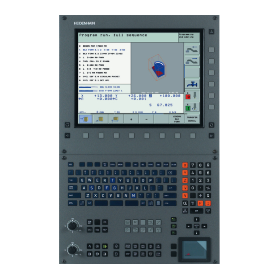
The picture is only an example as, of course, there exists a large selection of different machine tools and machining centers. Furhermore, it does not claim to be complete! Note On the cover page of this Service Manual and in the PDF file the highlighted HEIDENHAIN components are well visible. May 2006 12 – 119... -
Page 120: Hardware Identification
ID label (example) Note The most important information for the service are the unit designation and the Id.Nr.! In the following pictures the position of the ID label on the HEIDENHAIN components is displayed with arrows. Main computer, controller unit,... - Page 121 UV 105 Power Supply Unit The UV 105 serves to supply the power to the CC42x if a non- HEIDENHAIN inverter is used, or, if required, to supply additional power if a HEIDENHAIN inverter is used. If a non-HEIDENHAIN inverter system is used, the adapter connector is connected to X69 of the UV 105.
- Page 122 Only used for iTNC 530 single-processor Rear side TE 530, TE 530B Operating Panel with Touchpad Only used for iTNC 530 single-processor and dual-processor Rear side BF 150 Visual Display Unit 15.1-inch color flat panel display (1024 x 768 pixels) with horizontal...
- Page 123 BF 120 Visual Display Unit 10.4-inch color flat-panel display (640 x 480 pixels) with horizontal soft keys: Rear side BTS 1x0 Screen-Keyboard Switching Unit With the BTS 1x0, it is possible to connect two monitors and two operating panels to an MC 42x(B). Rear side MB 420 Machine Operating Panel Machine operating panel with snap-on (switchable) keys.
- Page 124 Two permissive buttons (24 V) Emergency-stop button (24 V) Magnetic holding pads Mount for attaching the handwheel to the machine HR 130 Handwheel Panel-mounted handwheel Rear side With ergonomic knob, radial cable outlet 12 – 124 HEIDENHAIN Service Manual iTNC 530...
- Page 125 HRA 110 Handwheel adapter For connecting up to three HR 150 handwheels to the TNC. The axes and the subdivision factor are selected via rotary switch. HRA 110 HR 150 with radial cabl outlet Handwheel selection switch Rear side May 2006 12 –...
- Page 126 Touch-trigger probe for measuring tools. TT 130 Adapter cable for connection to the MC 42x(B) lateral TS 220 Touch Probe Touch-trigger probe with cable connection for workpiece setup and measurement during machining. 12 – 126 HEIDENHAIN Service Manual iTNC 530...
- Page 127 TS 640, TS 440 Touch Probe Touch-trigger probe with infrared transmission, for workpiece setup and measurement during machining. TS 640 TS 440 SE 640 transmitter-receiver unit SE 540 transmitter-receiver unit TS 640 TS 440 SE 640 SE 540 May 2006 12 –...
- Page 128 The PL 510 can be mounted on a top hat rail (NS 35 EN 50022). The PL 510 equipped (completely or partially) with PLD 16-8 is compatible with PL 410 B/PL 405 B. PLB 510 Basic Module 12 – 128 HEIDENHAIN Service Manual iTNC 530...
- Page 129 PLD 16-8 input/output module PLA 4-4 analog module Empty housing lateral lateral PLD 16-8 PLA 4-4 May 2006 12 – 129...
-
Page 130: Display Of System Information
12.3 Display of System Information General When consulting your machine manufacturer or HEIDENHAIN in case of error or malfunction of your machine, it is important to know which software is installed on the iTNC. Calling the display Press the following keys to display the currently active NC software on the iTNC screen: ... - Page 131 Windows 2000 (dual-processor control) Due to restrictions on the export of the iTNC 530, HEIDENHAIN can also supply a special export version. This export version differs from the standard control through the installed NC software type.
- Page 132 The ICTL software designates the operating system for the digital signal processors (DSP) that are responsible for the speed control of digital axes/spindles. ICTL1: software for the main controller board, ICTL2: software for the additional controller board. 12 – 132 HEIDENHAIN Service Manual iTNC 530...
- Page 133 Display for NC software as of 340490-xx (with smarT.NC programming surface) Note As opposed to the display for the NC software types of 340420-xx to 340480-xx , the "feature content level" is here displayed. (The display for "preset table" and "OPT" is no longer required.) Please see previous picture for explanations of "NC: software number"...
- Page 134 12 – 134 HEIDENHAIN Service Manual iTNC 530...
-
Page 135: Connector Designation And Layout
13 Connector Designation and Layout 13.1 Important Note Caution Do not engage or disengage any plug and clamped connections while the unit is under power! 148! 13.2 MC and CC 13.2.1 Designation and Position of Connectors MC 422 with 5 position encoder inputs and CC 422 with 6 control loops X1 to X5 Position encoder 1 Vpp X35 to X38... - Page 136 X150, X151 at bottom of housing X167 Reserved 5V/0V Power supply for processor X150 Axis-specific drive release 1 to 6 X151 Axis-specific drive release 7 to 10 Signal ground Ground lead (YL/GN) 13 – 136 HEIDENHAIN Service Manual iTNC 530...
- Page 137 MC 422B with 5 position encoder inputs and CC 422 with 6 control loops X1 to X5 Encoder for position X35 to X38 Vacant X15 to X20 Encoder for speed X51 to X60 PWM output X8, X9 Nominal value output, analog TS touch trigger probe TT 130 touch trigger probe Handwheel...
- Page 138 X149 (X49) BF 150 (BF 120) visual display unit X131 Reserved Power supply X121, X125 Reserved X165, X166, X167 Reserved 5-V power supply X150/X151 Axis-specific drive release Signal ground Equipment ground (YL/GN) 13 – 138 HEIDENHAIN Service Manual iTNC 530...
- Page 139 MC 422B and CC 424 with max. 6 control loops X201 to X206 Encoder for position X15 to X20 Encoder for speed X51 to X60 PWM output X8, X9 Nominal value output, analog TS touch trigger probe TT 130 touch trigger probe Handwheel Ethernet data interface RS-232-C/V.24 data interface...
- Page 140 BF 150 (BF 120) visual display unit X150, X151 at bottom of housing X131 Reserved X69, X169 Power supply X121, X125, X165 Reserved 5-V power supply X150/X151 Axis-specific drive release Signal ground Equipment ground (YL/GN) 13 – 140 HEIDENHAIN Service Manual iTNC 530...
- Page 141 MC 420 and CC 422 with 6 control loops X1 to X5 Encoder for position X15 to X20 Encoder for speed X51 to X56 PWM output Nominal value output, analog TS touch trigger probe TT 130 touch trigger probe Handwheel Ethernet data interface RS-232-C/V.24 data interface RS-422/V.11 data interface...
-
Page 142: Pin Layouts On The Mc And Cc
Do not assign Violet Violet Do not assign Hsg. External shield Hsg. External shield Hsg. Hsg. External shield Note The interface complies with the requirements of EN 50 178 for “low voltage electrical separation.” 13 – 142 HEIDENHAIN Service Manual iTNC 530... - Page 143 X1 to X6, X35 to X38, X201 to X214: position encoder with EnDat interface 42x(B), AK 332 115-xx VB 323 897-xx AK 313 791-xx CC 424 Male Assign- Female Color Female Male Color Fem. Male Color ment Brown/ Brown/ Brown/ +5 V (UP ) 1 Green Green...
- Page 144 Analog output 9: 0 V Gray Analog output 10: 0 V Blue Analog output 12: 0 V Black Housing External shield Housing External shield a. Only for MC 422B, but not for MC 422 13 – 144 HEIDENHAIN Service Manual iTNC 530...
- Page 145 X12: Connection of the touch probe for workpiece measurement Note The interface complies with the requirements of EN 50 178 for “low voltage electrical separation.” Pin layout for TS 220: MC 42x(B) AK 274 543-xx TS 220 Female Assignment Male Color Color 0 V (internal shield)
- Page 146 0 V (UN) White White Trigger signal Trigger signal Green Green 11 to 15 Do not assign External Hsg. External shield Hsg. shield Hsg. Hsg. a. Stylus at rest means logic level HIGH. 13 – 146 HEIDENHAIN Service Manual iTNC 530...
- Page 147 Two EA 652 can be connected to the MC 422 via the APE 652. This is necessary for example on large machines or on machines with swivel heads. Pin layout for TS 632 with 2 EA 652 via the APE 652: MC 422 Adapter APE 652 VB 336 157-xx...
- Page 148 Do not assign Temperature – Violet Violet Hsg. Housing Hsg. External shield Hsg. Hsg. External Hsg. shield Note The interface complies with the requirements of EN 50 178 for “low voltage electrical separation.” 13 – 148 HEIDENHAIN Service Manual iTNC 530...
- Page 149 X15 to X20, X80 to X87: Speed encoder with EnDat interface CC 42x AK 336 376-xx VB 340 302-xx Male Assignment Female Color Female Color Female +5 V (UP) Brown/Green Brown/Green 0 V (UN) White/Green White/Green Green/Black Green/Black A– Yellow/Black Yellow/Black Blue/Black Blue/Black...
- Page 150 Violet Hsg. Housing Hsg. External shield Hsg. Hsg. External shield 2 tem- perature+ 3 tem- perature+ Note The interface complies with the requirements of EN 50 178 for “low voltage electrical separation.” 13 – 150 HEIDENHAIN Service Manual iTNC 530...
- Page 151 Pin layout (for the LC or RCN): CC 42x AK 336 376-xx AK 369 502-xx AK 369 124-xx AK 369 129-xx or RCN Male Assignment Female Color Female Male Color Female Male Color +5 V (UP) Brown/ Brown/ Brown/ Green Green Green 0 V (UN)
- Page 152 The interface complies with the requirements of EN 50 178 for “low voltage electrical separation.” Meanings of the LEDs on the Ethernet data interface X26: Condition Meaning Green Blinking Interface active Interface inactive 13 – 152 HEIDENHAIN Service Manual iTNC 530...
- Page 153 Condition Meaning Yellow 100 Mb net 10 Mb net X27: RS-232-C/V.24 data interface to HEIDENHAIN HeROS operating system Note The interface complies with the requirements of EN 50 178 for “low voltage electrical separation.” 25-pin adapter block: MC 42x(B) VB 365 725-xx...
- Page 154 The control-is-ready signal output is powered by 24 Vdc provided by the UE 2xx B inverter or the Power supply for UV1xx power supply unit. The voltage is connected with terminal X34. control is ready Connecting terminal Assignment Connection when using a HEIDENHAIN inverter +24 V X72/1 X72/2 13 – 154 HEIDENHAIN Service Manual iTNC 530...
- Page 155 X41: PLC outputs on the MC 42x(B) MC 42x(B) VB Id. Nr. 244 005-xx Id. Nr. 263 954-xx D-sub Assignment D-sub connctn. connctr. (female) (male) 37-pin 37-pin Supply via X44, pin 3; can be switched off with EMERGENCY STOP Gray/Red Brown/Black O2 a White/Black...
- Page 156 0 V (PLC) test output; do not assign Yellow/Pink 0 V (PLC) test output; do not assign Violet 0 V (PLC) test output; do not assign White Housing External shield Housing External shield 13 – 156 HEIDENHAIN Service Manual iTNC 530...
- Page 157 X44: Pin layout on the MC 422(B): PLC supply voltage Connection Assignment PLC outputs terminal +24 V cannot be switched O24 to O30 off via EMERGENCY STOP +24 V can be switched off O16 to O23 via EMERGENCY STOP O0 to O15 Note If the +24-V power supply (which cannot be shut off via emergency stop) is missing at X44, the error message Supply voltage missing at X44 appears.
- Page 158 RL21 Pink/Red RL22 Brown/Blue RL23 Pink/Green Spindle override Brown (wiper) Feed-rate override Yellow/Pink (wiper) +5 V override Violet potentiometer 0 V override White potentiometer Housing External shield Housing External Housing Housing shield 13 – 158 HEIDENHAIN Service Manual iTNC 530...
- Page 159 X46: PLC inputs I128 to I152 and PLC outputs O0 to O7 are on connection X46 of the machine Machine operating panel. The reference potential (PLC) for outputs O0 to O7 is connected to pins 34 operating panel and 35. Pin layout on the MC 42x(B), connecting cables and machine operating panel: Caution PLC inputs I128 to I152 must be switched only with the power supply from pins 36 and 37,...
- Page 160 Serial OUT Serial OUT White/Pink Serial OUT Address 4 Black Address 4 Address 2 Gray Address 2 Address 0 White Address 0 Housing External shield Housing External shield Housing Housing External shield 13 – 160 HEIDENHAIN Service Manual iTNC 530...
- Page 161 X47: PLC expansion for PL 510 on the MC 422(B) MC 42x(B) VB Id. Nr. 371 045-xx 1st PL 510 D-sub Assignment D-sub D-sub X1 D-sub Assignment connctn. connctr. connctr. connctn. (male) (female) (male) (female) 25-pin 25-pin 26-pin 26-pin Black Violet Do not assign 4 Do not assign...
- Page 162 Analog input 3: 0 V (reference potential) 20 to 25 Do not assign Housing External shield Note The interface complies with the requirements of EN 50 178 for “low voltage electrical separation.” 13 – 162 HEIDENHAIN Service Manual iTNC 530...
- Page 163 X49: BF 120 flat-panel display MC 42x(B), X49 VB Id. Nr. 340 300-xx BF 120, X2 D-sub Assign- D-sub D-sub D-sub connectn. ment connctr. connector connctn. (female) (male) (female) (male) 62-pin 62-pin 62-pin 62-pin Gray/Black CLK.P Brown/Black HSYNC Green/Black BLANK Orange/Black VSYNC Blue/Black...
- Page 164 53 to 56 Do not 53 to 56 Free 53 to 56 53 to 56 assign 57 to 62 57 to 62 Free 57 to 62 57 to 62 Housing Housing Housing Housing 13 – 164 HEIDENHAIN Service Manual iTNC 530...
- Page 165 X51 to X64: PWM-output Ribbon cable connector 20-pin Assignment PWM U1 0 V U1 PWM U2 0 V U2 PWM U3 0 V U3 0 V ( SH2) 0 V (SH1) +Iactl ! –Iactl 1 0 V (analog) +IACT 2 –Iactl 2 0 V (analog) Do not assign...
- Page 166 Do not assign PF.PS.ZK Reserved (SDA) ERR.UZ.GR Reserved (SLC) ERR.IZ.GR RES.LE ERR.TMP X74: 5-V connection of UV 105 Wire color of 5-V connection 5-V terminal on CC 42x Black + 5 V 13 – 166 HEIDENHAIN Service Manual iTNC 530...
- Page 167 X127: RS-232-C/V.24 data interface to Windows 2000 operating system Note The interface complies with the requirements of EN 50 178 for “low voltage electrical separation.” 25-pin adapter block: MC 42x(B) Connecting cable 365 725- Adapter block Connecting cable 310 085-01 545-xx Male Assignment...
- Page 168 Connection designation Function 24 V power supply 5-V output X140 USB input (to the MC 42x(B)) X141 USB output 1 X142 USB output 2 X143 USB output 3 X144 USB output 4 13 – 168 HEIDENHAIN Service Manual iTNC 530...
- Page 169 X147: PLC expansion for PL 510 on the MC 420 MC 420 Connecting cable Id. Nr. 371 045-xx First PL 510 D-sub Assignment D-sub D-sub Assignment connctn. connctr. connctr. D-sub (male) (female) (male) connctn. 26-pin 26-pin 26-pin (female) 26-pin Black Violet Do not assign 4 Do not assign...
- Page 170 Not assigned 25 to 30 25 to 30 31 to 39 LVDSGND 31 to 39 31 to 39 40 to 44 Not assigned 40 to 44 40 to 44 Housing Housing Housing Housing 13 – 170 HEIDENHAIN Service Manual iTNC 530...
- Page 171 X150, X151: The connecting terminals X150 and X151 are located on the bottom of the CC 42x. Drive-controller X150 controls drive enabling for the axis groups on the first controller board (PWM outputs enable for X51 to X56). axes groups X151 controls drive enabling for the axis groups on the second controller board (PWM outputs X57 to X60 or X62).
- Page 172 –15 V PF.PS.AC (only UV 120, UV 140, UV 150, UR 2xx) UZAN Do not assign IZAN Do not assign RES.PS Do not assign PF.PS.ZK Reserved (SDA) ERR.UZ.GR Reserved (SLC) ERR.IZ.GR RES.LE ERR.TMP 13 – 172 HEIDENHAIN Service Manual iTNC 530...
-
Page 173: Power Supply Units
13.3 Power Supply Units The iTNC 530 is supplied via connector X69 (X169) on the CC; see “X69: NC power supply and control signals, see X169” on page 13 – 166. Exception: An MC can be connected directly to a UV 106 (B), the CC is not required. This constellation is intended for machines with analog axes and spindle(s). -
Page 174: Uv 105 Power Supply Unit
Power supply for CC 42x (to X69 on CC 42x) Status signals from UV 1x0 Power supply Caution Do not engage or disengage any connecting elements while the unit is under power! 13 – 174 HEIDENHAIN Service Manual iTNC 530... - Page 175 The UV 105 is powered with dc-link voltage UZ through UV 105 with UZ the conductor bars (for HEIDENHAIN inverter systems). a cable which is connected instead of the conductor bar (for non-HEIDENHAIN inverter systems). X69: When connecting to connector X69/X169 of the CC, see “X69: NC power supply and control NC supply voltage signals, see X169”...
-
Page 176: Uv 105 B Power Supply Unit
Otherwise there will be a short circuit of these lines on the 5V ribbon wires of X69. 13.3.2 UV 105 B Power Supply Unit Connection overview UV 105 B Caution Do not engage or disengage any connecting elements while the unit is under power! 13 – 176 HEIDENHAIN Service Manual iTNC 530... - Page 177 Supply voltage: 400 V ± 10 % front panel Pin layout: Connecting terminal Assignment +UDC DC-link voltage of the non-HEIDENHAIN inverster system -UDC DC-link voltage of the non-HEIDENHAIN inverster system a. Connecting cable: 1.5 mm Equipment ground (YL/GY) Š 10 mm2...
-
Page 178: Uv 106 (B) Power Supply Unit
Do not engage or disengage any connecting elements while the unit is under power! X31: Supply voltage: 400 V ± 10 % Supply voltage for Pin layout: UV 106 (B) Connecting terminal Assignment a. Connecting cable: 1.5 mm Equipment ground (YL/GY) Š 10 mm2 13 – 178 HEIDENHAIN Service Manual iTNC 530... -
Page 179: Inverters And Motors
For further information, refer to the Service Manual "Inverter Systems and Motors". 13.5 Interface Boards for the SIMODRIVE System 611D The HEIDENHAIN expansion boards for the SIMODRIVE system receive PWM signals from the control and converts them. --> see “X51 to X64: PWM-output” on page 13 – 165. -
Page 180: Encoders
Please note: The adapters adjust only the levels, not the signal shape. The contamination signal of the square-wave encoder cannot be evaluated. A square-wave signal can be subdivided no more than 4-fold. 13 – 180 HEIDENHAIN Service Manual iTNC 530... - Page 181 Adapter connector Pin layout of D-sub connector (female) and D-sub connector (male): TTL (HEIDENHAIN)/ 1 Vpp D-sub connctr. Assignment D-sub connectn. Assignment (female) 15-pin (male) 15-pin +5 V (UP) +5 V (UP) 0 V (UN) 0 V (UN) A– –Ua1 B–...
-
Page 182: Speed Encoders
See “X12: Connection of the touch probe for workpiece measurement” on page 13 – 145. systems for workpiece measurement Touch probe See “X13: Connection of the touch probe for tool measurement” on page 13 – 147. systems for tool measurement 13 – 182 HEIDENHAIN Service Manual iTNC 530... -
Page 183: Handwheels
13.8 Handwheels X23: See “X23: Handwheel input” on page 13 – 152. Handwheel input 13.8.1 HR 4xx Portable Handwheel The HR 4xx is a portable electronic handwheel. Assignment of the keys of the HR 410 to the PLC inputs and outputs. -->... - Page 184 Dummy plug for EMERGENCY STOP circuit 271 958-03 Connecting cable Spiral cable 312 879-01 Normal cable 296 467-xx Metal armor tubing 296 687-xx Plug-in terminal strips 3-pin terminal block 266 364-06 4-pin terminal block 266 364-12 13 – 184 HEIDENHAIN Service Manual iTNC 530...
-
Page 185: Hr 130 Panel-Mounted Handwheel
13.8.2 HR 130 Panel-Mounted Handwheel Standard cable length for the HR 130 is 1 meter. Pin layout for extension cable and handwheel: Extension cable ID 281 429-xx HR 130 ID 254 040-xx D-sub connctr. D-sub connctr. D-sub connctr. (male) 9-pin (female) 9-pin (male) 9-pin Housing... - Page 186 The power supply of the PLC must not be used simultaneously for the HRA110, otherwise the metallic isolation of the PLC inputs/outputs would be bridged. HRA 110 Connecting terminal Assignment + 24 Vdc as per IEC 742 (VDE 551) Maximum current consumption 200 mA. 13 – 186 HEIDENHAIN Service Manual iTNC 530...
-
Page 187: Plc Input/Output Units
13.9 PLC Input/Output Units 13.9.1 Designation and Position of Connectors PL 405 B +24V SUPPLY +24V +24V +24V +24V May 2006 13 – 187... - Page 188 PL 410B +24V SUPPLY +24V +24V +24V +24V +24V SUPPLY ANALOG 13 – 188 HEIDENHAIN Service Manual iTNC 530...
- Page 189 PL 510 PLB 510 Basic Module PLD 16-8 input/output modulePLA 4-4 analog module May 2006 13 – 189...
-
Page 190: Pl 4Xxb Pin Layouts
Serial OUT Serial OUT White/Pink Serial OUT Address 4 Black Address 4 Address 2 Gray Address 2 Address 0 White Address 0 Housing External Housing External shield Housing Housing External shield shield 13 – 190 HEIDENHAIN Service Manual iTNC 530... - Page 191 Terminal Assignment PLC inputs 1. PL 2. PL 3. PL 4. PL PL 410 B and I192 I256 I320 PL 405 B I193 I257 I321 I194 I258 I322 I195 I259 I323 I196 I260 I324 I197 I261 I325 I198 I262 I326 I199 I263 I327...
- Page 192 I120 I248 I312 I376 I121 I249 I313 I377 I122 I250 I314 I378 I123 I251 I315 I379 I124 I252 I316 I380 I125 I253 I317 I381 I126 I254 I318 I382 I127 I255 I319 I383 13 – 192 HEIDENHAIN Service Manual iTNC 530...
- Page 193 Terminal Assignment PLC output 1. PL 2. PL 3. PL 4. PL PL 410 B O128 O160 O129 O161 O130 O162 O131 O163 O132 O164 O133 O165 O134 O166 O135 O167 O136 O168 O137 O169 O138 O170 O139 O171 O140 O172 O141 O173...
- Page 194 The power supply must comply with EN 50 178, 5.88 requirements for ”low analog inputs voltage electrical separation.” on the PL 410 B Terminal Assignment +24 Vdc as per EN 50 178, 5.88 +0 V 13 – 194 HEIDENHAIN Service Manual iTNC 530...
-
Page 195: Pin Layout Pl 510
13.9.3 Pin Layout PL 510 See “X47: PLC expansion for PL 510 on the MC 422(B)” on page 13 – 161. PLC expansion on the MC 422 (B) See “X147: PLC expansion for PL 510 on the MC 420” on page 13 – 169. PLC expansion on the MC 420 Pin Layout on PLB 510 Basic Module... - Page 196 I270 I271 Slot 2 I280 I281 I282 I283 I284 I285 I286 I287 Slot 3 I296 I297 I298 I299 I300 I301 I302 I303 Slot 4 I312 I313 I314 I315 I316 I317 I318 I319 13 – 196 HEIDENHAIN Service Manual iTNC 530...
- Page 197 Assignment Terminal Fourth PL 510 Slot 1 I328 I329 I330 I331 I332 I333 I334 I335 Slot 2 I344 I345 I346 I347 I348 I349 I350 I351 Slot 3 I360 I361 I362 I363 I364 I365 I366 I367 Slot 4 I376 I377 I378 I379 I380 I381...
- Page 198 LEDs must be established at X4 or X5. The iTNC 530 cyclically monitors the PLC outputs of the PL510 for a short circuit. Pin layout at X6 (power supply for PLC outputs):...
-
Page 199: Machine Operating Panel
13.10 Machine Operating Panel 13.10.1 Designation and Position of Connectors on MB 420 13.10.2 Pin Layouts on MB 420 See “X46: Machine operating panel” on page 13 – 159. Connection to MC The NC start key and the NC stop key are connected with the MB 420 via X2. Connection of NC start and NC stop Terminal... -
Page 200: Itnc Keyboard
PLC outputs Terminal Assignment 13.11iTNC Keyboard 13.11.1 Designation and Position of Connectors TE 420 13 – 200 HEIDENHAIN Service Manual iTNC 530... -
Page 201: Pin Layouts
TE 530 (B) 13.11.2 Pin Layouts Pin layout of the iTNC keyboard: Connection of the Connecting element (male) 9-pin Assignment softkeys of visual display unit to the iTNC keyboard Do not assign RL15 RL14 RL13 RL12 See “X45: iTNC keyboard unit” on page 13 – 158. iTNC keyboard See “X141, X142: USB connection”... -
Page 202: Visual Display Units
13.12Visual Display Units 13.12.1 Designation and Position of Connectors BF 120 BF 150 13 – 202 HEIDENHAIN Service Manual iTNC 530... -
Page 203: Pin Layouts
13.12.2 Pin Layouts Power supply with basic insulation in accordance with EN 50 178: Power supply Connecting terminal X1 Assignment +24 V Power consumption: BF 120: 15 W BF 150: 45 W See “X49: BF 120 flat-panel display” on page 13 – 163. Connection of the BF 120 to the MC See “X149 BF 150 flat-panel display”... -
Page 204: Bts 1X0 Monitor/Keyboard Switch
At X4 +24 V At X5 Power supply with double insulation in accordance with EN 50 178: Supply voltage for Connecting terminal Assignment BTS 1x0 +24 V Current consumption: Max. 100 mA. 13 – 204 HEIDENHAIN Service Manual iTNC 530... -
Page 205: Power Supply
--> The MC is directly connected to the UV 106 (B). This makes it possible to operate analog axes and spindles exclusively. Note The iTNC 530 (MC/CC) powers the connected units, such as scales, motor encoders, touch probes, handwheel, transmitter-receiver units. Exceptions: The screen has its own connection for power supply. - Page 206 UV 105. The UV xxx does not have an additional 5 V terminal and thus cannot power the iTNC 530 sufficiently. The 50-line ribbon cable X69 of the UV xxx is connected to the UV 105 so that the status signals of the UV xxx can be transmitted to the iTNC.
- Page 207 The UV 105 is not required! Note When using HEIDENHAIN inverters that are not provided with the additional 5 V terminal on the front panel (e.g., UR xxx D, UV xxx D, UVR xxx, UVR xxx D), an accessory unit for the power supply of the iTNC 530 is not required.
- Page 208 Power Supply The UV 105 B was designed solely for the use on HEIDENHAIN controls in connection with non- by UV 105 B HEIDENHAIN inverter systems. The phases U/V and the dc-link voltage ± UDC are connected via a connector on the front panel.
- Page 209 Power supply An MC 42x (B) can also be connected to a UV 106 (B) instead of a CC 42x controller unit. Thus by UV 106 (B) the control loops for digital axes and spindles are not required. --> This combination is solely destined for analog axes and spindles.
-
Page 210: Uv 105, Uv 105 B
Measure whether the 5 V voltage on the auxiliary terminal of the UV 105 (B) is available. terminal Note If you have the HEIDENHAIN test adapter with the corresponding ribbon cable, you can connect it parallel to the 50-line ribbon cable of the UV 105 (B) and measure the corresponding low voltages. - Page 211 Uz of a non- When using a non-HEIDENHAIN inverter system (e.g., Simodrive 611), the power supply from HEIDENHAIN the dc link is mostly lead via a protective PCB. This is secured to the conductor bar on the non- inverter system HEIDENHAIN inverter.
- Page 212 Use insulated pincers when removing the fuses! Caution Be careful not to touch any components on the power supply board sensitive to electrostatic discharge and observe the ESD regulations! Position of the fuses in the UV 105 14 – 212 HEIDENHAIN Service Manual iTNC 530...
- Page 213 Position of the fuses in the UV 105 B Note If any of the fuses is defective, the UV 105 (B) power supply unit must be replaced. Replacing the fuses is not advised. Mounting the UV 105 (B) DANGER For mounting the UV 105 (B), the additional 5V lines must be connected with the correct polarity! Otherwise there will be a short circuit of these lines on the 5V ribbon wires.
-
Page 214: Uv 106, Uv 106 B
It is not useful to measure the low voltages on the 50-line ribbon cable of the UV 106 (B) (e.g., with the HEIDENHAIN test adapter). The MC could not be connected and the UV 106 (B) would operate without current consuming unit. - Page 215 Fuses in Switch off the main switch of the machine. UV 106 (B) Dismantle the UV 106 (B) power supply unit. Ensure that the unit is not under power. Remove the side plate. Check the fuses on the power supply board. DANGER Danger of electrical shock! A switching power supply is located in the UV 106 (B).
-
Page 216: Power Supply For Control-Is-Ready Signal
It is a prerequisite that the "Control-is-ready" signal output is integrated correctly in the EMERGENCY STOP chain --> see “Basic Circuit Diagrams” on page 11 – 116, see “During Booting” on page 9 – 55! 14 – 216 HEIDENHAIN Service Manual iTNC 530... -
Page 217: Buffer Battery
14.3 Buffer Battery General If the machine is switched off, the power for the RAM is supplied by the buffer battery. The rated voltage is 3 V. The lifetime of the buffer battery is typically three to five years. For safeguarding the RAM, an additional capacitor (Gold cap) was integrated onto the PCB of the iTNC. - Page 218 Battery type: 1 lithium battery, type CR 2450N (Renata), Id. Nr. 315878-01 Caution Be careful not to touch any components sensitive to electrostatic discharge and observe the ESD regulations! Position of the buffer battery of the MC 422 Buffer battery 14 – 218 HEIDENHAIN Service Manual iTNC 530...
- Page 219 Position of the Buffer Battery of the MC 422 B Buffer Battery Note If the battery was exchanged although the Gold cap was not loaded sufficiently, the battery- buffered areas of the working memory are deleted. The non-volatile PLC markers and words belong to this area.
-
Page 220: Info Menu
Note These values are updated internally in the minutes cycle. The display is only updated with the new call of the Info menu. I.e., the code number 79513 must be entered again. 14 – 220 HEIDENHAIN Service Manual iTNC 530... -
Page 221: Power Supply For The Display Units
14.5 Power Supply for the Display Units Power supply with basic insulation in accordance with EN 50 178: Connecting terminal X1 Assignment +24 V Power consumption:BF 120: 15 W BF 150: 45 W May 2006 14 – 221... -
Page 222: Power Supply For Plc Outputs
14.6 Power Supply for PLC Outputs 14.6.1 General The PLC of the iTNC 530 as well as the PL 410B/PL 405B/PL 510 are powered by the 24 Vdc control voltage of the machine (in accordance with VDE 0551). The control voltage must be smoothed with a minimum 1000 µF at a rated current capacity of 150 µF/A. -
Page 223: Supply Voltage For Plc Outputs On The Mc
14.6.2 Supply Voltage for PLC Outputs on the MC X44: PLC supply voltage Pin layout on the MC 422(B): Connection Assignment PLC outputs terminal +24 V cannot be switched O24 to O30 off via EMERGENCY STOP +24 V can be switched off O16 to O23 via EMERGENCY STOP O0 to O15... - Page 224 Switch main switch of machine off Dismount MC (before doing so, label cables and/or connectors, if required.) Check fine-wire fuses on PLC board Fine-wire fuses o.k.? Replace fine-wire fuses MC probably defective (PLC board, etc.) 14 – 224 HEIDENHAIN Service Manual iTNC 530...
-
Page 225: Supply Voltage For Plc Outputs On The Pl 4Xx B
Fine wire fuses Caution Use only original replacement fuses. Be careful not to touch any components sensitive to electrostatic discharge and observe the ESD regulations! 14.6.3 Supply Voltage for PLC Outputs on the PL 4xx B Connection May 2006 14 – 225... - Page 226 The power supply must comply with EN 50 178, 5.88 requirements for ”low analog inputs voltage electrical separation.” on the PL 410 B Terminal Assignment +24 Vdc as per EN 50 178, 5.88 +0 V 14 – 226 HEIDENHAIN Service Manual iTNC 530...
- Page 227 On older PLC expansion boards PL 4xx B, you may still find fine-wire fuses (glass fuses) on the board. These may be replaced, if necessary: On newer PL 4xx B, the glass fuse has been replaced by an SMD fuse. The SMD fuse has been soldered onto the board. Contact your HEIDENHAIN service agency. May 2006...
-
Page 228: Supply Voltage For Plc Outputs On The Pl 510
14.6.4 Supply Voltage for PLC Outputs on the PL 510 Note The iTNC 530 cyclically monitors the supply voltage and short circuits of the PLC outputs of a PL 510. Connection PLB 510 basic Pin layout for X3 (power supply for logic circuit):... - Page 229 Error The corresponding PLC outputs do not function. Depending on the PLC program of the machine manufacturer, corresponding PLC error messages are displayed. Note Monitoring the PLC outputs. --> see “The TABLE Function” on page 10 – 76. Functional control Ensure that: The green LEDs on X6 pin9 and pin10 of the I/O modules PLD16-8 are lit.
- Page 230 14 – 230 HEIDENHAIN Service Manual iTNC 530...
-
Page 231: Hard Disk And File Manager Of The Itnc 530
15 Hard Disk and File Manager of the iTNC 530 15.1 Introduction The TNC data and the PLC data are located on the hard disk of the iTNC 530 as well as the complete NC software, including the setup files. -
Page 232: Structure Of The Hard Disk
807667. SYS: System-specific data The complete NC software including setup files is located here (NC dialogs, HEIDENHAIN cycles, etc.) and the HeROS operating system (HEIDENHAIN Real Time Operating System). A daily password is required to open the SYS partition. Caution Changes to the SYS partition can result in a malfunction of your TNC. -
Page 233: Hard Disk Test
Additional and more comprehensive tests can only be performed at HEIDENHAIN agencies! Caution Do not use your own hard-disk test or repair programs! This could complicate or make it impossible for HEIDENHAIN or specialized companies to rescue data. With the single- Each time the control is booted, the SYS partition is tested (file-system check). - Page 234 -a /dev/hda1 (is displayed in the log only in case of an error!) Note If the NC software cannot be started with the defective hard disk and thus the log cannot be called, contact your HEIDENHAIN service agency for further possibilities to investigate the hard disk! 15 – 234...
- Page 235 First close all programs in Windows before you activate the test programs. This also applies to the iTNC application! Changes in Windows may influence the function of the control! HEIDENHAIN cannot guarantee the function of Windows applications! You can use the following test routine: ...
- Page 236 If no error has been detected, the error message Disk Check Complete is displayed. If you find an error, please contact HEIDENHAIN! Note The same test can also be performed with the Command Prompt and the command chkdsk , e.g., chkdsk C: 15 –...
-
Page 237: Setting The System Time
The setting of the system time of single-processor controls is only explained in the HEIDENHAIN service courses. control If necessary, contact the HEIDENHAIN hotline! In machine parameter MP 7235, the difference between local time and system time can be entered. - Page 238 Subsequently, set the current datum and the local time. 15 – 238 HEIDENHAIN Service Manual iTNC 530...
-
Page 239: File Management Of Tnc Partition (Tnc:\)
15.5 File Management of TNC Partition (TNC:\) Calling the Press the following key combination to call the TNC partition: TNC partition Select the Programming and Editing operating mode Call Program Management The directory structure is displayed on the left. The associated files are listed on the right. - Page 240 This file has dependent files (see User's Manual) Date Date on which file was last changed Time Time at which file was last changed Note Refer to the iTNC 530 User’s Manual for detailed information about file management! 15 – 240 HEIDENHAIN Service Manual iTNC 530...
-
Page 241: File Management Plc Partition (Plc:\)
15.6 File Management PLC Partition (PLC:\) Calling the PLC Press the following key combination to call the PLC partition: partition Select the Programming and Editing operating mode Call window for code number Enter and confirm code number ... - Page 242 This filter can be removed by pressing the soft keys SELECT TYPE --> SHOW ALL . Which File Type is to be Listed? Use this key to switch between soft-key rows. 15 – 242 HEIDENHAIN Service Manual iTNC 530...
- Page 243 This file has dependent files (see User's Manual) Date Date on which file was last changed Time Time at which file was last changed Note Refer to the iTNC 530 User’s Manual for detailed information about file management! May 2006 15 – 243...
- Page 244 15 – 244 HEIDENHAIN Service Manual iTNC 530...
-
Page 245: Data Backup
(machine parameter, PLC program, etc.), a new backup for this machine must be created! Available For the data backup of the iTNC 530 the following data interfaces are available (standard): data interfaces An Ethernet interface Connector X26 An RS 232 interface (V.24) - Page 246 The picture shows the correct default setting in the TNCremoNT configuration. Note The data of a iTNC 530 are archived externally in the defined ASCII format as the BINARY format on the control can be changed, e.g., after an NC software update.
-
Page 247: Connection Setup
NET123 and pressing the DEFINE NET soft key. With the dual-processor control, the IP settings of Windows are managed. The HEIDENHAIN code number NET123 has no effect. You can enter the command ipconfig in the prompt. Subsequently read the settings in the line Ethernet adapter Local Area Connection. - Page 248 Now search the place where you can call and edit the characteristics of the TCP/IP Protocol. In the following example (Windows 2000) the characteristics of the TCP/IP protocol are stored in LAN connection --> Properties --> Internet protocol (TCP/IP) --> Properties. 16 – 248 HEIDENHAIN Service Manual iTNC 530...
- Page 249 Click on Properties to display the following window: Caution Note down the original settings which you will have to restore later! For the following changes to the setting of you Ethernet card, you require the corresponding permissions. Contact your system administrator. ...
- Page 250 At the prompt enter, e.g., the command ipconfig ... or your enter the command winipcfg (depending on the Windows version). You can also find this information in My Computer\Control Panel\Network ... 16 – 250 HEIDENHAIN Service Manual iTNC 530...
- Page 251 Now back up the original network settings of the iTNC 530: With the dual-processor control, write down the original network settings. With the single-processor control, these DEFINE NET settings are filed in a certain file ... Call the PLC partition (PLC code number) and subsequently the program manager.
- Page 252 Press END twice. The control now reboots. TNCremoNT Start the HEIDENHAIN data transfer program TNCremoNT. Click this icon to open the configuration window (can also be opened via Extras/Configuration ...). Now click on Connection and select TCP/IP (Ethernet connection).
- Page 253 The TNCremo screen is divided and the control's hard disk is shown in the lower half of the screen. If this does not work, please check the connecting cable and the settings! Note If the following error message is displayed during connection establishment, … ...
- Page 254 If the "pinging" does not function, you have to check again all settings and the hardware (Ethernet cables, Ethernet cards). Meaning of the LEDs on the ethernet data Condition Meaning interface X26 Green Blinking Interface active Interface inactive Yellow 100 Mb net 10 Mb net 16 – 254 HEIDENHAIN Service Manual iTNC 530...
- Page 255 Restoring the After having finished data back-up and separated the connection, do not forget to restore the original settings original network settings of your laptop or of the iTNC. Enter the original settings and confirm with ENTER. Delete the newly inserted line in the network settings of the control. --> The line with the original settings moves again to the top-most position.
-
Page 256: Via Serial Interface Rs 232/V.24 Or Rs 422/V.11
You can select the highest possible baud rate. If there are transmission problems, you can back on lower baud rates. Note The iTNC 530 recognizes automatically when the LSV-2 protocol is used (e.g., data transfer with TNCremoNT). It is not necessary to set the line Operating mode! TNCremoNT ... - Page 257 Check the transmission mode (binary-ASCII conversion). It should be set as follows: Confirm with Apply and OK. Click this icon. --> The connection is established. The TNCremo screen is divided and the control's hard disk is shown in the lower half of the screen.
-
Page 258: Reading In And Out Of Individual Files Or Directories
Introduction Note Information on setting data interfaces and reading in and out of data (e.g., TNCserver operation) can be found in the User's Manual for the iTNC 530. Establish conntection to the iTNC 530 by means of TNCremoNT Connection setup -->... - Page 259 Using the mouse, click the file you wish to download. Press the left mouse button and move the file to its destination (upper window). Release the mouse button. --> The file is transferred. Note During downloading the data format is automatically converted from BINARY (control) to ASCII (laptop/PC) via TNCremoNT.
- Page 260 Press the left mouse button and move the file to its destination (lower window). Release the mouse button. --> The file is transferred. Note During uploading the data format is automatically converted from ASCII (laptop/PC) to BINARY (control) via TNCremoNT. 16 – 260 HEIDENHAIN Service Manual iTNC 530...
-
Page 261: Backup
It would be ideal that during backup the control is in the Power interrupted state. Set up a connection to the iTNC 530 by means of the TNCremoNT. Connection setup --> see “Connection Setup” on page 16 – 247. - Page 262 Activate the backup menu with this icon (or via Extras/Backup/Restore ... )! Miscellaneous backup types The following window appears: 16 – 262 HEIDENHAIN Service Manual iTNC 530...
- Page 263 The backup type can be selected via the following icons … Scan directory The files in the selected directory are scanned. Files in subdirectories are ignored! Scan directory tree The files in the selected directory and in all subdirectories are scanned. ...
- Page 264 If the data transfer has been completed successfully, there are two files on the laptop: *.BCK backup file with the original files in compressed format *.LST reference list containing the directories and the files 16 – 264 HEIDENHAIN Service Manual iTNC 530...
-
Page 265: Extracting Files From The Backup File
16.5 Extracting Files from the Backup File General If you want to create a backup (e.g. of the PLC partition), all related files are stored in one *.bck file using a compression algorithm. To view individual files (e.g., MP list OEM.SYS, etc.) you can extract them from the *.bck file by means of TNCremoNT! Extracting a file ... -
Page 266: Restore
--> see “Extracting Files from the Backup File” on page 16 – 265. Set up a connection to the iTNC 530 by means of the TNCremoNT Connection setup --> see “Connection Setup” on page 16 – 247. - Page 267 Restore Doubleclick on the LST file to open it. starting Start the data transfer with menu item Run/Restore or the corresponding icon. Confirm the following warning with OK. Confirm the message regarding automatic reset of control with Yes and continue data transfer.
- Page 268 1. Load MPNAME.MP into the editor (as long as the original MP list is open for editing, it cannot be restored). 2. Load the entire backup to the control again. 3. Reboot the control. 16 – 268 HEIDENHAIN Service Manual iTNC 530...
-
Page 269: Data Interface Operating Modes
16.7.1 Overview of Operating Modes The iTNC can be set for data transfer according to the following interface operating modes: For connection of the HEIDENHAIN floppy-disk unit FE 401B or other peripheral units. This operating mode is supported by TNCremo/TNCremoNT. -
Page 270: Interface Configuration And Assignment Of Mode
To leave the interface settings press the END soft key. Note The iTNC 530 recognizes automatically, when the LSV-2 protocol is used (e.g., data transfer with TNCremoNT). It is not necessary to set the line Operating mode! 16 – 270... -
Page 271: Drive Symbols
16.8 Drive Symbols When you call program management in the Programming and editing operating mode, the different drives are displayed. RS 232:\ V.24 data interface (X27) RS 422:\ V.11 data interface (X28) TNC:\ TNC partition (user data) PLC:\ PLC partition (machine data via code number) Depending on the type of operating mode set, a symbol appears beside the external drive. -
Page 272: Cable Overview
The reason can be the different potential of the power supply of both units. HEIDENHAIN therefore recommends to use the so called "opto bridge". This serial adapter connector ensures a metallic isolation via opto coupler and can thus protect the serial interface against overvoltage, different load potentials and interference voltages on the ground lines. -
Page 273: Rs-232-C/V.24
Exception: The cable with the Id.No. 366964-xx may be connected to the 9-pin adapter block or directly to the control. The serial data interfaces are described in detail in the Data Interfaces Service Manual of HEIDENHAIN Devices. Download under www.heidenhain.de/Services/... Overview: May 2006... - Page 274 Cable assignment: 16 – 274 HEIDENHAIN Service Manual iTNC 530...
- Page 275 May 2006 16 – 275...
- Page 276 Metallically isolates the serial interface by means of integrated opto couplers and thus protects from: - Overvoltages - Different load potentials by different main current circuits - Interference voltlages on ground lines 16 – 276 HEIDENHAIN Service Manual iTNC 530...
- Page 277 D-sub adapter connector 25-pin To test the data transfer lines display by LEDs D-sub adapter connector 25-pin To cross the data transfer lines D-sub adapter connector Adaptation of 25-pin connector to 9-pin connector Background: The adapter block RS 232 on the switch cabinet mostly has a 25-pin connector, the COM interface on the laptop mostly has a 9-pin connector.
-
Page 278: Rs-422/V.11
The RS-422-/V.11 data interface has the same pin layout at the iTNC (connector X28) and at the V.11 adapter block (D-sub connector on the switch cabinet). The serial data interface are described in detail in the Data Interfaces Service Manual of HEIDENHAIN Devices. Download under www.heidenhain.de/Services/... 16 – 278 HEIDENHAIN Service Manual iTNC 530... -
Page 279: Encoder Interface
17 Encoder Interface 17.1 Position Encoders 17.1.1 Introduction Position encoders report positions and movements of the machine to the control. The iTNC 530 operates with incremental and absolute encoders with EnDat interface. Linear position encoders include scales and scale tapes. -
Page 280: Possible Causes Of Error
With encoders with a reference mark, an error message is not generated immediately. The refernce run does not function properly and the axis moves, e.g., to the limit switch. 17 – 280 HEIDENHAIN Service Manual iTNC 530... -
Page 281: Service Diagnosis
17.1.3 Service Diagnosis To find out whether the connected encoder or the control interface is defective, you can operate the encoder with another interface of the control. Use the interface of a functioning axis. Caution If the scanning head is wet and thus a short circuit is caused, it must not be connected again! Encoder interfaces are not always short-circuit proof. - Page 282 (in the example from X to Y) The defect is probably located in the position Defect is located in the position encoder input of the control encoder or the encoder cable 17 – 282 HEIDENHAIN Service Manual iTNC 530...
-
Page 283: Additional Diagnosis Possibility On Encoders With Endat Interface
17.1.5 Corrective Action If you have found out that the interface on the control is defective: Exchanging the control --> See “Exchange of HEIDENHAIN Components” on page 26 – 411. If you have found out the the scanning head/scale/cable is defective: Exchange the encoder or the encoder component or corrective action (e.g., cleaning of scale). -
Page 284: Re-Setting The Machine Datum
Add the value to the value entered in MP 960.x for the axis concerned. Enter the sum in MP960.x. Check whether the reset machine datum is correct (e.g., with M91)! If required, reset the traverse range to the original value. 17 – 284 HEIDENHAIN Service Manual iTNC 530... - Page 285 Gantry axes Always tro to mount the scale as exactly as possible to its original position! Set MP860.x to 0 for the slave axis. (After the reference marks have been traversed, no compensating motion is made.) Set the display to REF. --> You can now see the current axis position referring to the machine datum..
-
Page 286: Speed Encoders
MP 112.x is not active for the CC 424. There is a fixed assignment of speed encoder inputs to the PWM outputs as in the following table: Drive control board PWM output Speed encoder input (MP120.x/MP121.x) 17 – 286 HEIDENHAIN Service Manual iTNC 530... -
Page 287: Possible Causes Of Error
Drive control board PWM output Speed encoder input (MP120.x/MP121.x) The the encoder inputs and PWM outputs are only be selected via MP120.x/MP121.x. All speed encoder inputs operate with 1 Vpp and areEnDat-compatible. For digital axes the speed encoders are always monitored! Motor encoders with EnDat interface can be provided with a so-called electronic ID label. - Page 288 MP 112.0 : 16 Assignment for exchange: MP 112.1 : 15 Y-Axis Y-Axis Original assignment: MP 112.1 : 16 Note Always exchange both, the cable and interface assignment by means of machine parameters! 17 – 288 HEIDENHAIN Service Manual iTNC 530...
-
Page 289: Trouble Shooting On Cc The 422
Flowchart Flowchart for diagnosing an error in the speed encoders circuit Interchanging the motor encoders of CC 422 Switch the main switch of the machine off Interchange the speed encoder cables of the axes concerned at CC 422 (in the example: Connectors X15 and X16) Switch the main switch of the machine on Do not confirm the Power interrupted message but immediately call the MP list and in... - Page 290 If different PWM frequencies are entered in parameter group MP 2180.x, ask the machine manufacturer or HEIDENHAIN for further service measures (the assignment of the machine parameter blocks for the current or speed controller by means of MP 130.x must also be regarded).
- Page 291 Flowchart Flowchart for diagnosing an error in the speed encoders circuit Interchanging the motor encoders of CC 424 Switch the main switch of the machine off Interchange the speed encoder cables of the axes concerned at CC 424 (in the example: Connectors X15 and X16) Unscrew the cover plate from the inverter system Interchange the PWM ribbon cables of the axes concerned at CC 424...
-
Page 292: Additional Diagnosis Possibility On Encoders With Endat Interface
If you have found out that the interface on the control is defective … Exchange the control. --> See “Exchange of HEIDENHAIN Components” on page 26 – 411. If you have found out that the motor encoder in a synchronous motor is defective (the... -
Page 293: Resetting The Spindle Orientation
If you want to exchange the motor encoder of the asynchronous motor: Read the instruction in the service manual "Inverter Systems and Motors". Use the enclosed mounting instructions (all motor encoders are supplied with mounting instructions). 17.2.7 Resetting the Spindle Orientation DANGER Ask the machine operator and regard the machine manufacturers's safety instructions (setup mode, etc.)! -
Page 294: Error Code For Encoders With Endat Interface
Read the checksum 0x90000000 Alarm bit remains set 0xA0000000 Timeout while waiting for data - signal “high” 0xC0000000 Timeout while waiting for data - signal “low” 0x80000000 Error during access to EnDat interface 17 – 294 HEIDENHAIN Service Manual iTNC 530... -
Page 295: Checking Position And Speed Encoders
Various adapters have been developed to permit PWM8 measurement of the different encoder signals (11 µApp, 1 Vpp, TTL) at iTNC 530. You will find a connection diagram of the adapters and ID numbers in the PWM 9 operating manual. -
Page 296: Position Measurement With The Motor Encoder
A defective scale or scanning head or a defective encoder cable could influence the low voltages actions of the control. This could have an effect on the overall function! Switch off the machine and separate the position encoder from the control! 17 – 296 HEIDENHAIN Service Manual iTNC 530... - Page 297 Enter the value from MP 1054.x (distance of one motor revolution) in MP 331.x. Enter the line count of the motor encoder (visible e.g. in the diagnostics functions of iTNC 530 or in the motor table) in MP 332.x. Exit the MP list and switch the machine on.
- Page 298 MP 331.x of the master. Enter the line count of the motor encoder (visible e.g. in the diagnostics functions of iTNC 530 or in the motor table) in MP 332.x of the master. Exit the MP list and switch the machine on...
- Page 299 Additional The following flow chart shows the interrogation whether the currents (I nominal) of the gantry information on gan- axes deviate considerably. A maximum tolerable current value cannot be given as different try axes drives, motors and mechanical designs are used. A misalignment of the gantry axes may be the result, for example, of the emergency stop of the machine when the scale failed.
- Page 300 MP 331.x of the axis concerned. Enter the line count of the motor encoder of the gantry axis concerned (visible e.g. in the diagnostics functions of iTNC 530 or in the motor table) in MP 332.x. Exit the MP list and switch the machine on.
-
Page 301: Referencing
Reference marks HEIDENHAIN linear encoders are designed with one or more reference marks. The reference marks identify an axis position at a known distance from the machine datum. The position of the freely selectable datum is defined with respect to the machine datum. -
Page 302: Traversing The Reference Marks
In MP 4130.x a fast PLC input is defined for an external reference pulse. In MP 1360.x the number of the fast PLC input is entered for the axis concerned. MP 1350.x = 6 for the axis concerned. 18 – 302 HEIDENHAIN Service Manual iTNC 530... - Page 303 If use of multiturn encoders with EnDat interfaces results in overruns, the corresponding information is entered in the system file NCDATA.SYS. For a control exchange, this file must be transferred or MP960.x must be readjusted (see “Exchange of HEIDENHAIN Components” on page 26 – 411)!
- Page 304 1 to 5: Fast PLC input for reference pulse (MP4130.x) MP1360.x Fast PLC input for reference pulse Input: 0: No fast PLC input for reference pulse 1 to 5: Fast PLC input for reference pulse (MP4130.x) 18 – 304 HEIDENHAIN Service Manual iTNC 530...
- Page 305 Position encoder Function when MP1350.x = 3 with distance- coded reference marks Reference marks Trip dog "Reference end position" Closed Open Traverse direction MP1320 May 2006 18 – 305...
- Page 306 If during automatic referencing the trip dog is not closed until it is in the reference end position range, the contouring control will ignore this signal. It is therefore necessary that there are at least two reference marks in the range of the reference end position. 18 – 306 HEIDENHAIN Service Manual iTNC 530...
- Page 307 Position encoder Function when MP1350.x = 1 with one reference mark Reference marks Trip dog Closed "Reference end position" Open Traverse direction MP1320 Press the external START key Trip dog "Reference end position" closed? Machine traverse in direction from MP1320 with velocity from MP1330.x to the trip dog "Reference end positon"...
- Page 308 Ensure that during referencing the same reference pulse is always evaluated. encoder This can be realized with the trip dog for reference end position. Measuring length Reference pulse Desired reference pulse Trip dog Closed "Reference end position" Open Traverse direction MP1320 18 – 308 HEIDENHAIN Service Manual iTNC 530...
-
Page 309: Deselect Referencing For Axes
18.3 Deselect Referencing for Axes For axis examinations it is possible to deselect the referencing MP 1340.x. Enter value 0 (= no evaluation of the reference mark) for the corresponding axis. Note In MP1340.x the sequence for the reference mark run is listed. With following entries, i.e.: MP1340.0 : 3 MP1340.1 : 2... - Page 310 18 – 310 HEIDENHAIN Service Manual iTNC 530...
-
Page 311: Checking The Enables On The Itnc
19 Checking the Enables on the iTNC 19.1 General With an operating axis (axis in control) ... No terminal symbol is shown The "STIB" star (control in operation) is shown. The feed rate enable must not be highlighted. The position display changes in case of a movement. Position display READY symbol... - Page 312 Drives ready for operation (on the HEIDENHAIN inverter system the green LEDs READY at the drive modules UM xxx or at the output stages of a compact inverter) must be lit. Note If a drive is taken in control, there must be a READY signal from the drive module after a defined time.
-
Page 313: Examination
--> See “Integrated Diagnosis Functions” on page 7 – 41. These diagnosis functions can be used for the following examinations! Selection of the Select the power supply unit used (not all status information of non-HEIDENHAIN inverters can mostly be used): supply device May 2006 19 – 313... -
Page 314: Examination Of The Output Control-Is-Ready (X41/Pin34) And Input Control-Is-Ready Signal Acknowledgement I3 (X42/Pin 4)
MC is probably defective. output Control is Ready (connector X34/PIN1 = 24V, PIN2 = 0V)? -> Replace the MC! Find the reason and correct the error. (Make use of the circuit diagram of the machine.) 19 – 314 HEIDENHAIN Service Manual iTNC 530... - Page 315 Page from the DSP Call via the soft keys DIAGNOSIS --> DRIVE DIAGNOSIS --> DSP diagnosis of drives See “Integrated Diagnosis Functions” on page 7 – 41. Excerpt from the Here you can see the terminals that can be measured basic circuit (the PLC inputs and outputs are mostly connected to a strip in the electrical cabinet).
- Page 316 (The function of this terminal can be set with a sliding switch on the rear side of the corresponding I/O modules, setting 1 = "Control is ready", See “X6: PLC outputs on the PL 510” on page 13 – 197) Sliding switch on I/O module 19 – 316 HEIDENHAIN Service Manual iTNC 530...
- Page 317 -> Replace the relay. Caution If 24 V is supplied to the control-is-ready output from the HEIDENHAIN inverter system via connector X34, potential differences between the 24 V machine voltage and the 24 V from the inverter can result in compensating currents.
- Page 318 The function of the Control-is-ready output of an I/O module PLD 16-8 can also be tested with this method. Note Course of the emergeny stop (or booting) routine. --> See “Monitoring Functions” on page 9 – 55! 19 – 318 HEIDENHAIN Service Manual iTNC 530...
-
Page 319: Checking The Global Drive Enable I32, Connector X42 / Pin 33
Drive diagnostics window still cannot operate the digital (or check in the PLC TABLE, whether axes/spindle, please call your I32 is set). machine tool builder or HEIDENHAIN! Acknowledgment present Is an (green indicator or NC-STOP signal pending? I32 = 1) ? (marker 4560 = 0)? Find the reason (e.g. - Page 320 (the PLC inputs and outputs are mostly connected to a strip in the electrical cabinet). diagram Drive enabling Drive enabling for all axes for axis groups Do not connect, If MP2040 = 0 19 – 320 HEIDENHAIN Service Manual iTNC 530...
-
Page 321: Checking The Drive Enabling For The Axis Groups Via Connector X150 And X151 (If Wired)
19.2.3 Checking the Drive Enabling for the Axis Groups via Connector X150 and X151 (if Wired) Check whether 24V are available for the axis group to be traversed. The axis groups for the drive enabling via X150 (main DCB) and X151 (auxiliary DCB) are defined in MP2040. -
Page 322: Checking The Readiness Of The Inverter System
19.2.4 Checking the Readiness of the Inverter System Selection of the Select the power supply unit used for the integral diagnosis functions (mostly not all status information of non-HEIDENHAIN inverters can be used): power supply unit Green “READY” ... - Page 323 Check according to the integrated drive diagnosis whether the power modules are ready: Open the electrical cabinet and also check whether the green READY-LEDs on the compact inverter or the power supply unit light up (a non-HEIDENHAIN inverter is probably also equipped with a corresponding LED or display). Inverters...
- Page 324 This is for example the case with clamped axes or if a spindle is not controlled. SH2 and READY are on simultaneously. Note HEIDENHAIN interface cards for the SIMODRIVE system: The cards for the plug-type connectors (ribbon cables) are equipped with the green READY LED and the red LEDs SH1 and SH2.
-
Page 325: Modules, Markers And Words
19.2.5 Checking PLC Modules, Markers and Words For the following investigations, the PLC diagnosis functions are used. --> See “PLC Diagnosis” on page 10 – 73. For these PLC analyses it might be helpful or often even necessary to contact the machine manufacturer for support. - Page 326 In the binary format this is 0100 1111 and in the decimal format this is the value 79. $ 0 0 4 F = HEX 0 1 0 0 1 1 1 1 = BIN Value of indivdual places 0+4+0+0 8+4+2+1 Place value considered 0+64+0+0 + 8+4+2+1 = DEC 19 – 326 HEIDENHAIN Service Manual iTNC 530...
-
Page 327: Interface To The Drives
The digital servo amplifiers are controlled via so-called PWM interfaces (PWM = Pulse Width Modulation). The position, speed and current controllers are located in the HEIDENHAIN control. Following PWM interfaces are located on the CC 422 / 424 controller unit... -
Page 328: Possible Causes Of Errors
Error in the NC or PLC software Wear and tear of mechanical parts Deterioration of the machine Defective HEIDENHAIN interface board for the SIMODRIVE 611 drive system Wrong grounding in connection with the so-called HEIDENHAIN interface boards There is wide variety of possible error causes. -
Page 329: Trouble Shooting: Exchanging Pwm Outputs On The Cc 422
If different PWM frequencies are entered in parameter group MP 2180.x, ask the machine manufacturer or HEIDENHAIN for further service measures (the assignment of the machine parameter blocks for the current or speed controller by means of MP 130.x must also be regarded). - Page 330 Block dDiagram Note Always exchange both, the cable and interface assignment by means of machine parameters! Note It is not relevant for this test routine which drive modules are connected! 20 – 330 HEIDENHAIN Service Manual iTNC 530...
- Page 331 Flowchart CC 422 Interchanging the PWM outputs of CC 422 Switch off the main switch of the machine tool. Unscrew the cover plate from the inverter system. Interchange the PWM ribbon cables of the axes concerned at CC 422 (in the example: Connectors X51 and X52).
- Page 332 If you have found out that the interface on the CC 422 is defective … Exchanging the CC. --> See “Exchange of HEIDENHAIN Components” on page 26 – 411. If you have detected that the error is outside the control (servo amplifier, motor, cable, etc.): Start the following routine.
-
Page 333: Trouble Shooting: Exchanging Pwm Outputs On The Cc 424
If different PWM frequencies are entered in parameter group MP 2180.x, ask the machine manufacturer or HEIDENHAIN for further service measures (the assignment of the machine parameter blocks for the current or speed controller by means of MP 130.x must also be regarded). - Page 334 Block Diagram Note Always exchange both, the cable and interface assignment by means of machine parameters! Note It is not relevant for this test routine which drive modules are connected! 20 – 334 HEIDENHAIN Service Manual iTNC 530...
- Page 335 Flowchart CC 424 Interchanging the PWM outputs of CC 424 Switch off the main switch of the machine tool. Unscrew the cover plate from the inverter system. Interchange the PWM ribbon cables of the axes concerned at CC 424 (in the example: Connectors X51 and X52). CAUTION: Handle the ribbon cable connectors with care! Do not bend the pins! Connect the motor encoder cables to the correct...
- Page 336 If you have found out that the interface on the CC 424 is defective … Exchanging the CC --> See “Exchange of HEIDENHAIN Components” on page 26 – 411. If you have detected that the error is outside the control (servo amplifier, motor, cable, etc.): Start the following routine.
-
Page 337: Trouble Shooting: Exchanging Power Modules Or Output Stages Of The Same Type
Or the power stage or output stage of a functioning axis Note It is not necessary to exchange a machine parameter for this test routine! It does not matter whether the power stages are from HEIDENHAIN or other manufacturers. Caution If you strongly suspect that the motor of the axis to be examined causes a short circuit (penetration of humidity, etc.), you must not connect it to another power stage as it could... - Page 338 X392, X393, X394, depending on the model. --> see Service Manual for Inverter Systems and Motors)! Motor brakes can be connected to current HEIDENHAIN inverter modules and compact inverters. The motor brake is also powered via a connector on the inverter. The trigger signals for the motor brakes are transmitted via the PWM bus.
- Page 339 Flowchart for two 1-axis modules Interchanging power modules of the same type Switch off the main switch of the machine tool. Unscrew the cover plate from the inverter system. Interchange the PWM ribbon cables of the axes concerned at the power modules or output stages (in the example: connectors X111).
-
Page 340: Trouble Shooting: Exchanging The Heidenhain Interface Boards For The Simodrive 611 System
20.1.6 Trouble Shooting: Exchanging the HEIDENHAIN Interface Boards for the SIMODRIVE 611 System If a SIMODRIVE 611 system is used in connection with the HEIDENHAIN control, there are HEIDENHAIN interface boards in the Siemens drive modules to adapt the PWM signals. -
Page 341: Analog Drives
The position controller is located in the MC, speed and current controller in the servo amplifier. The HEIDENHAIN control also supplies the nominal speed value. This is why the ± 10V interface is also designated as nominal speed value interface. - Page 342 No terminal symbol before the axis concerned must be shown. The feed rate display (F …) must not be highlighted. The "STIB" star (control in operation) must be shown. If necessary, ask the machine operator! 20 – 342 HEIDENHAIN Service Manual iTNC 530...
- Page 343 Flowchart If nevertheless one or several analog axes do not function, you may investigate the following: Analog axis does not move Switch the machine off and connect a multimeter to the terminal strip of the servo amplifier of the axis to be checked. (Use the circuit diagram of the machine.) Switch off the main switch of the machine.
- Page 344 Battery box If available, you can investigate whether the analog servo amplifier can be operated with a "Battery box" (not a HEIDENHAIN unit). This battery box replaces the control and provides the analog servo amplifier with a nominal speed value of ± 10 V.
- Page 345 Specifications of the analog outputs Load capacity: RL Š 5 kW, I £2 mA CL £ 2 nF Short-circuit stability: one output short-circuit proof at a time Voltage range: Uamax = +10 V ± 100 mV Uamin = -10 V ± 100 mV Resolution: 14 bit = 16 384 steps Smallest step:...
-
Page 346: Adjusting The Electrical Offset (Drift Adjustment)
If you receive the error message EXCESSIVE OFFSET <AXIS>. Note The drift adjustment only needs to be carried out with analog axes. Offset Adjustment Analog servo amplifiers are no HEIDENHAIN products. at servo amplifier Follow the instructions of the servo manufacturer (operating instructions, etc.)! Here are two proposals. - Page 347 Axes to be adjusted must be in control (if necessary, ask the machine manufacturer). Switch position display to LAG. Adjust the offset at the servo amplifier until the individual axes either display the value 0 or oscillate around 0 (approximate value ± 3-5 µm). Note Use also the integrated oscilloscope with the settings s actual, s nominal, s diff.
- Page 348 Later changes in offset are not compensated. Do not carry out an offset compensation, or end a previous compensation. Exit the menu without making any changes. 20 – 348 HEIDENHAIN Service Manual iTNC 530...
-
Page 349: Speed Adjustment At Servo Amplifier (Tachometer Adjustment)
(Vnom = Vact). Note Adjusting only needs to be carried out with analog axes. Execution Analog servo amplifiers are no HEIDENHAIN products. Follow the instructions of the servo manufacturer (operating instructions, etc.)! Here is a proposal: ... - Page 350 It might be helpful to use the integrated oscilloscope. The signals Vnoml and Vactl can be recorded and compared. The quality of the speed adjustment can thus be controlled and improved, if required. Comparison of noml. and actl. speed in the integrated oscilloscope 20 – 350 HEIDENHAIN Service Manual iTNC 530...
-
Page 351: Switching The Position Display For Service Purposes
20.3 Switching the Position Display for Service Purposes Call Press the following key combination to switch the position display: Select a machine operating mode (manual, Program Run, Full Sequence, etc.). Activate MOD function. Press GOTO to open a list box. Description of set- Possible position displays: tings... - Page 352 20 – 352 HEIDENHAIN Service Manual iTNC 530...
-
Page 353: Visual Display Unit
21 Visual Display Unit 21.1 General One of the two flat-panel displays are connected to the iTNC 530: BF 150 with horizontal and vertical soft keys BF 120 with horizontal soft keys The BF is … supplied with 24 V dc voltage from the electrical cabinet power supply unit. -
Page 354: Fault Diagnosis
Subsequently, search the error of the connected unit including cable. Note If you have found out that the screen itself is defective, then a further inspection of the flat- panel display is not possible without special test equipment. 21 – 354 HEIDENHAIN Service Manual iTNC 530... - Page 355 Rear view BF 120 Rear view BF 150 May 2006 21 – 355...
- Page 356 21 – 356 HEIDENHAIN Service Manual iTNC 530...
-
Page 357: Keyboard Unit
If HR 420 electronic handwheel is active, the operation of the machine via keypad is locked. For iTNC 530 single-processor controls a TE 420 can be used; for dual-processor controls, however, a mouse pad and additional Windows keys are required (Te 530, 530 B). - Page 358 TE 530 (with mouse pad and additonal Windows keys) TE 530 B (with additonal smarT.NC keys) 22 – 358 HEIDENHAIN Service Manual iTNC 530...
-
Page 359: Possible Causes Of Error
TE 520 B (with additional smarT.NC keys, without mouse pad) 22.3 Possible Causes of Error Note Defective keys cannot contact any more or are in continuous contact. Strong contramination --> Key gets caught Jammed chips --> Key gets caught Defective contact --> Key does not report to the control any more Penetrated liquid Defective keypad board Defective cable between screen and keypad (screen softkeys) -
Page 360: Checking The Keys
KEYTEST.A. The keys pressed on the ASCII field (blue keys) are displayed directly. Other keys mostly generate the message "Key non-functional" or a corresponding reaction, e.g., change to a machine operating mode. 22 – 360 HEIDENHAIN Service Manual iTNC 530... - Page 361 Principle of the key The keys are evaluated via a matrix. Every key is located above a crosspoint of SL (= scan line) and RL (= return line). --> see “Key Matrix of the Keyboard Units” on page 22 – 367 or see “Key matrix Matrix of the Keyboard Units”...
- Page 362 A continuity test of the cross points of scan lines (SL) and the return line 0 (RL 0) is not possible. There are logical gates between RL 0 and the corresponding keys. These gates serve as keypad identifier as of TE 5 xx. A direct ohmic measuring is thus not possible. 22 – 362 HEIDENHAIN Service Manual iTNC 530...
- Page 363 The functioning of the keypad interface on the MC can also be tested with the test adapter: Disconnect the keypad from the MC. Connect the test adapter instead to connector X45 of the MC. You can now simulate the pressing of keys by bridging the corresponding pin sockets on the test adapter.
-
Page 364: Checking The Potentiometers
The advantage of this method is that possible wiper interruptions of the potentiometers can be recognized better than in the PLC TABLE. For this investigation the machine must be switched on completely! 22 – 364 HEIDENHAIN Service Manual iTNC 530... - Page 365 Measuring setup with test adapter Procedure: Switch off the machine. Insert the measuring adapter at the MC connector X45 between MC and TE cable. Switch the machine on again. Using a multimeter, check the wiper voltages of the potentiometers. Potentiometers Voltage range Feed rate override F%...
-
Page 366: Checking The Mouse Pad
(the laptop must be equipped with a Windows operating system with the corresponding mouse driver). Note As the touch pad is managed by Windows, there are also the corresponding Windows settings. --> "My computer/Control Panel/Mouse…" 22 – 366 HEIDENHAIN Service Manual iTNC 530... -
Page 367: Key Matrix Of The Keyboard Units
22.7 Key Matrix of the Keyboard Units TE 420 X2 pin key 1 17 18 19 28 29 31 32 20 21 22 23 24 25 26 27 16 17 18 19 20 21 22 SL0 May 2006 22 – 367... - Page 368 X2 pin key 1 17 18 19 28 29 31 32 20 21 22 23 24 25 26 27 16 17 18 19 20 21 22 SL0 22 – 368 HEIDENHAIN Service Manual iTNC 530...
- Page 369 X2 pin key 1 17 18 19 28 29 31 32 20 21 22 23 24 25 26 27 16 17 18 19 20 21 22 SL0 May 2006 22 – 369...
- Page 370 X2 pin key 1 17 18 19 28 29 31 32 20 21 22 23 24 25 26 27 16 17 18 19 20 21 22 SL0 22 – 370 HEIDENHAIN Service Manual iTNC 530...
- Page 371 X2 pin key 1 17 18 19 28 29 31 32 20 21 22 23 24 25 26 27 16 17 18 19 20 21 22 SL0 May 2006 22 – 371...
- Page 372 TE 530, TE 530 B, TE 520 B X2 Pin HOME BREAK SCROL 22 – 372 HEIDENHAIN Service Manual iTNC 530...
- Page 373 X2 Pin & May 2006 22 – 373...
- Page 374 X2 Pin 22 – 374 HEIDENHAIN Service Manual iTNC 530...
- Page 375 X2 Pin CAPS LOCK May 2006 22 – 375...
- Page 376 X2 Pin SHIFT " links 22 – 376 HEIDENHAIN Service Manual iTNC 530...
- Page 377 X2 Pin < > SHIFT CTRL rechts links links May 2006 22 – 377...
- Page 378 X2 Pin Ctrl SPACE rechts rechts Kont links rechts 22 – 378 HEIDENHAIN Service Manual iTNC 530...
- Page 379 X2 Pin APPR C H F R N D CALC HELP May 2006 22 – 379...
- Page 380 X2 Pin CYCL TO UCH CYCL STOP PROBE CALL CALL 22 – 380 HEIDENHAIN Service Manual iTNC 530...
- Page 381 X2 Pin TO O L GOTO TO O L PG M CALL CALL Note The two keys left of the touch pad do not belong to the key matrix! If these keys are pressed, the signal is transmitted to the control via USB interface. May 2006 22 –...
-
Page 382: Key Matrix Of The Keyboard Units
Key on visual display unit Connection for ribbon cable display unit => keyboard unit (plug-type connector) Connection for cable keyboard unit => MC (D-Sub 37-pin) SK = Soft key (SK1..SK8 from left to right) 22 – 382 HEIDENHAIN Service Manual iTNC 530... - Page 383 BF 150 X1 pin X2 pin RL12 RL13 RL14 RL15 a. Connector on the keyboard unit b. Key on visual display unit Connection for ribbon cable display unit => keyboard unit (plug-type connector) Connection for cable keyboard unit => MC (D-Sub 37-pin) SK = Horizontal soft keys (SK1..SK8 from left to right) MF = Vertical soft keys (MF1..MF6 from top to bottom)
- Page 384 22 – 384 HEIDENHAIN Service Manual iTNC 530...
-
Page 385: Machine Operating Panel
23 Machine Operating Panel 23.1 General For machines with up to four axes, HEIDENHAIN offers the MB 420 machine operating panel. It is normally mounted below the TNC keyboard. The machine operating panel is connected to connector X46 of the MC. -
Page 386: Checking The Power Supply
Insert the test adapter at the MC connector X1 between MC 420 and connecting cable. Switch the machine on again. Using a multimeter, check the supply voltage on the corresponding PINs. 23 – 386 HEIDENHAIN Service Manual iTNC 530... -
Page 387: Checking The Keys
23.3 Checking the Keys Possible Strong contramination --> Key gets caught causes of error Jammed chips --> Key gets caught Defective contact --> Key does not report to the control any more Defective keypad board Defective cable MB control Defective interface on the control Note Due to an interruption of the NC stop signal (lowactive) between MB and control, the machine cannot be traversed any more. - Page 388 You can measure the input voltages, e.g. on terminal X3 of the MB 420 or via test adapter on connector X1. --> see “Test Adapter, ID 375830-01” on page 29 – 456. 23 – 388 HEIDENHAIN Service Manual iTNC 530...
-
Page 389: Checking The Outputs
23.4 Checking the Outputs The MB 420 is provided with 8 PLC outputs (e.g., the lamps of the buttons can be controlled). These outputs are located on the connecting leads X1 and also on terminal block X4: Terminal X4 Assignment The function can be checked via the table for the PLC outputs: Call the table with the PLC outputs. - Page 390 23 – 390 HEIDENHAIN Service Manual iTNC 530...
-
Page 391: Handwheel
Pin layouts and wiring (e.g., EMERGENCY STOP key and permissive key on cable adapter) --> see “Handwheels” on page 13 – 183. For information on the operation of the electronic handwheels. --> See User's Manual iTNC 530. Caution HEIDENHAIN recommends to check the function of the EMERGENCY STOP switch on the... - Page 392 Connect the test adapter between connector X23 of the MC and handwheel and measure the +12 V voltage (see “Test Adapter, ID 375830-01” on page 29 – 456) If available, connect a dimensionally identical handwheel and test the functioning. 24 – 392 HEIDENHAIN Service Manual iTNC 530...
-
Page 393: Hr 420 Portable Handwheel With Display
24.2 HR 420 Portable Handwheel with Display 24.2.1 Checking the Keys The keys cannot contact any more (defective contact, line, etc.) or are in continuous contact (adhesion of the key by strong contamination, jammed chips, etc.). With the PLC diagnostic functions TABLE or LOGIC DIAGRAM you can check the function of many handwheel keys my means of the corresponding PLC markers: ... -
Page 394: Checking The Potentiometers
Press the CTRL and Handwheel keys in the HR 420. --> The TNC shows the soft-key menu for selecting the potentiometers on the handwheel display. Press the KBD soft key to activate the potentiometers of the machine operating panel. 24 – 394 HEIDENHAIN Service Manual iTNC 530... - Page 395 By means of W494 the function of the feed-rate override potentiometer, and by means of W492 the function of the spindle override potentiometer can be controlled: Press EMERGENCY STOP. Activate the HR 420 (press the handwheel symbol on the HR 420). ...
-
Page 396: Hr 410 Portable Handwheel
Evaluation of the keys via the NC. --> MP7645.0 = 0 Low feed Medium High feed rate feed rate rate – O109 O110 O111 I173 I174 I175 All keys are evaluated by the NC except the keys A, B and C! 24 – 396 HEIDENHAIN Service Manual iTNC 530... - Page 397 Evaluation of the keys via the NC. --> MP7645.0 = 1 Note Ask the machine manufacturer if MP 7645.0 can be changed for test purposes. It is possible that this is not permitted by the PLC program. I160 I161 I162 I163 O100 O103...
-
Page 398: Hr 150 Panel-Mounted Handwheels With Hra 110 Handwheel Adapter
Call the table with the PLC inputs. --> see “The TABLE Function” on page 10 – 76. Turn the selective switches. Using the following tables, check whether the corresponding inputs change to 0. 24 – 398 HEIDENHAIN Service Manual iTNC 530... - Page 399 Assignment of the The tables below list the assignments of switch positions of S1 and S2 to the switch positions to PLC inputs I160 to I175. the PLC inputs The two switches work with a 0 V logic circuit. Example: If switch S1 is in position 3, input I162 is logically 0, and all other inputs are logically 1.
- Page 400 24 – 400 HEIDENHAIN Service Manual iTNC 530...
-
Page 401: Touch Probe
25 Touch Probe 25.1 General Information An iTNC 530 can be equipped with different touch probes. Touch probe with signal transmission via cable (e.g. TS 220) These touch probes are inserted manually into the spindle by the machine operator. They serve the purpose of aligning work pieces, setting datums and calibrating workpieces. - Page 402 The corresponding mounting instructions The brochure 3-D Touch Probes for Machine Tools These documents can be downloaded from the HEIDENHAIN website (www.heidenhain.de). If you cannot find the requested document, ask the machine manufacturer or your HEIDENHAIN service agency! Note The power supply of the touch probes is not monitored.
-
Page 403: Touch Trigger Probe With Cable Connection For Workpiece Setup And Measurement
Defective interface of probe on MC Note After a collision, check the accuracy of the touch probe. Ask the machine manufacturer or your HEIDENHAIN service agency! Control of the LEDs Red LEDs on the TS 220 signalize, that the stylus is deflected:... - Page 404 0 V (UN) are on pin 8 --> see “X12: Connection of the touch probe for workpiece measurement” on page 13 – 145 TS 220 Note If available, you can also test a dimensionally identical probe and test the functions! 25 – 404 HEIDENHAIN Service Manual iTNC 530...
-
Page 405: Touch Trigger Probe With Infrared Transmission For Workpiece Setup And Measuring
Note After a collision, check the accuracy of the touch probe. Ask the machine manufacturer or your HEIDENHAIN service agency! Control of the LEDs By means of two multi-color LEDs, an optical status control of the SE 440, SE 640 and EA 632 transmitting/receiving units is possible: LED with the "flash"... - Page 406 (X12/pin10) 0 V --> Probe ready, stylus at rest 0 V (UN) are on pin 8 --> see “X12: Connection of the touch probe for workpiece measurement” on page 13 – 145 25 – 406 HEIDENHAIN Service Manual iTNC 530...
- Page 407 TS 640 with SE 640 Note If available, you can also test a dimensionally identical probe and test the functions! TS 440 with SE 540 May 2006 25 – 407...
-
Page 408: Triggering Touch Probe For Tool Measurement
Trigger signal negates (X12/pin10) --> Probe ready, stylus at rest 0 V (UN) are on pin2. --> see “X13: Connection of the touch probe for tool measurement” on page 13 – 147, X13 25 – 408 HEIDENHAIN Service Manual iTNC 530... - Page 409 TT 130 Note If available, you can also test a dimensionally identical probe and test the functions! May 2006 25 – 409...
- Page 410 25 – 410 HEIDENHAIN Service Manual iTNC 530...
-
Page 411: Exchange Of Heidenhain Components
(partly due to the above reasons). Note The NC software update for the single-processor and dual-processor control is described in the Technical Manual iTNC 530 which is available to the machine manufacturer! May 2006 26 – 411... - Page 412 Repair Many HEIDENHAIN units are not repaired at site but are exchanged or replaced. These units are exclusively repaired by HEIDENHAIN specialists. The units are also tested and updated to the latest state-of-the-art. ID numbers For a service order, always indicate the ID number of the corresponding HEIDENHAIN unit.
- Page 413 If the machine data are missing (data loss, replacement control, new control) the control opens the file MPNAME.MP: The file MPNAME.MP is generated by the HEIDENHAIN operating system. The axes cannot be traversed, and the control is set to programming station.
- Page 414 The number is displayed on the screen after entering the SIK code. It can also be found on the SIK housing or on a sticker below the ID label of the MC. 26 – 414 HEIDENHAIN Service Manual iTNC 530...
- Page 415 Feature content When a new version is released as of NC software 340490-xx (with smarT.NC programming level surface), the ranges for error fixes and expanded functions are managed separately. When the NC software is updated to a new version, first only the included error fixes will be effective.
- Page 416 Electronic ID label HEIDENHAIN inverter components of type D, as well as HEIDENHAIN synchronous motors with absolute encoders with EnDat interface, are equipped with an electronic ID label. The product name, the ID number and the serial number are saved in this ID label. These devices are automatically detected when the control is started.
- Page 417 ESD protection Caution When exchanging HEIDENHAIN components, you might come into contact with electronic components. These ESD-sensitive components could also come into contact with a statically loaded object (tool, tool table, packaging, etc.). Therefore, when exchanging MC, CC, HDR, drive assembly and all units with openly...
-
Page 418: Exchanging The Mc 422
If you cannot back up data on the defective MC 422 anymore, you must go back to available archives (PLC data, TNC data) to back up the data on the new control. If required, you may obtain the machine data also from the machine manufacturer. 26 – 418 HEIDENHAIN Service Manual iTNC 530... - Page 419 Removing the Switch off main switch of the machine and take precautions against resetting. --> See “Safety Precautions” on page 1 – 9! defective MC 422 Label and remove all of the connections on the MC. Loosen two torx screws at the top and two at the bottom of the housing (do not screw off completely).
- Page 420 If required, remove the protective caps from the MC connectors. Re-establish and screw into place all the connections. Caution Do not forget the grounding screw! Do not confuse any of the connectors! Switch on main switch of machine. 26 – 420 HEIDENHAIN Service Manual iTNC 530...
- Page 421 It is not predictable, to which CC the MC 422 is connected by the customer. It may thus happen that the MPNAME.MP of your CC has too many or insufficient control-loop indexes. But this is not a problem! By deleting the MPNAME.MP, the iTNC 530 generates an MPNAME.MP that correlates to your CC.
- Page 422 The backed up MP file matches the older NC software version. Advantage: If you want to install another (older) NC software version for servicing, there also exists the appropriate MP list. Press the END key. The following messages may be generated: 26 – 422 HEIDENHAIN Service Manual iTNC 530...
- Page 423 After each change, try to activate the machine parameter list with END. If the MP list is complete, the iTNC 530 makes a restart. Reset non-volatile Write the non-volatile PLC markers and words from the hard disk into the RAM before confirming the power interrupt message.
- Page 424 Please fill in this form and attach it to the housing of the MC 422. Pack the defective MC 422 in the original packaging of the new MC 422. Return the defective MC 422 to the machine manufacturer or to your HEIDENHAIN service agency. 26 – 424 HEIDENHAIN Service Manual iTNC 530...
-
Page 425: Removing The Drive Assembly
26.3 Removing the Drive Assembly Caution The drive assembly may only be exchanged in consultation with the machine manufacturer or by the machine manufacturer! Drives that you receive in exchange and new drives are already partitioned and formatted. The HeROS operating system and the NC software are installed (the hard disks are normally equipped with the current NC software). - Page 426 Connect MC 422 to the CC and screw into place. Re-establish and screw into place all the connections. Caution Do not forget the grounding screw! Do not confuse any of the connectors! Switch on main switch of machine. 26 – 426 HEIDENHAIN Service Manual iTNC 530...
- Page 427 It may thus happen that the MPNAME.MP of your CC has too many or insufficient control-loop indexes. But this is not a problem! By deleting the MPNAME.MP, the iTNC 530 generates an MPNAME.MP correlates to your CC. Note As of NC software version 340420-08, the code number NET 123 for setting up the Ethernet configuration is also accepted with open MP list.
- Page 428 LST file, the new LIES_MP.A is not overwritten by the old LIES_MP.A. It is not recommended to protect the LIES_MP.A file on the control as otherwise the file cannot be updated during an NC software update! 26 – 428 HEIDENHAIN Service Manual iTNC 530...
- Page 429 Updating the If the control opens the machine parameter list after you have restored the back up, new machine machine parameters are added with the current NC software of the replacement hard disk or parameter list older MPs are removed. Note In this case the following tip for an NC software update might be interesting: Copy the original MP file (e.g., MachineXYZ.MP).
- Page 430 Apply a note with the error description on the sheet metal of the drive assembly. Pack the defective drive assembly in the original packaging of the new drive assembly. Return the defective drive assembly to the machine manufacturer or to your HEIDENHAIN service agency. 26 – 430 HEIDENHAIN Service Manual iTNC 530...
-
Page 431: Exchanging The Mc 422 B Or The Mc 420
26.4 Exchanging the MC 422 B or the MC 420 Preparing the If still possible … machine Move machine to home position (axed, tool changer, tilting head, etc.). Ask the machine operator! Press EMERGENCY-STOP. Backup of Back up the condition of non-volatile PLC markers and words from RAM to the HDR. -->... - Page 432 Pack the defective MC 422 B in the original packaging of the new MC 422 B. Return the defective MC 422 B to the machine manufacturer or to your HEIDENHAIN service agency. 26 – 432 HEIDENHAIN Service Manual iTNC 530...
-
Page 433: Exchanging The Hdr
26.5 Exchanging the HDR Caution The drive assembly may only be exchanged in consultation with the machine manufacturer or by the machine manufacturer! Drives that you receive in exchange and new HDRs are already partitioned and formatted. The HeROS operating system and the NC software are installed (the HDRs are normally equipped with the current NC software). - Page 434 --> See “Safety Precautions” on page 1 – 9! defective HDR Press the handle of the HDR upwards to loosen the locking. Press the locking hook upwards and remove the HDR. 26 – 434 HEIDENHAIN Service Manual iTNC 530...
- Page 435 Remove the SIK from the defective HDR and insert it into the new HDR. Caution The SIK (System Identification Key) will remain with the machine. It must be inserted into the new or replacement HDR; i.e. all enabled options are still available.
- Page 436 The HeROS operating system and the current NC software are installed (for dual-processor controls also Windows 2000 is available on hard disk). The control boots with this software. If you need another version, please contact your machine manufacturer! Switch on the machine. 26 – 436 HEIDENHAIN Service Manual iTNC 530...
- Page 437 It may thus happen that the MPNAME.MP of your CC has too many or insufficient control-loop indexes. But this is not a problem! By deleting the MPNAME.MP, the iTNC 530 generates an MPNAME.MP correlates to your CC. Note As of NC software version 340420-08, the code number NET 123 for setting up the Ethernet configuration is also accepted with open MP list.
- Page 438 LST file, the new LIES_MP.A is not overwritten by the old LIES_MP.A. It is not recommended to protect the LIES_MP.A file on the control as otherwise the file cannot be updated during an NC software update! 26 – 438 HEIDENHAIN Service Manual iTNC 530...
- Page 439 Updating the If the control opens the machine parameter list after you have restored the back up, new machine machine parameters are added with the current NC software of the replacement HDR or older parameter list MPs are removed. Note In this case the following tip for an NC software update might be interesting: Copy the original MP file (e.g., MachineXYZ.MP).
- Page 440 Restoring the On machines with analog axes, an offset fine adjustment should be performed with the HEIDENHAIN code number after the exchange of the control. -> See “Adjusting the Electrical default settings Offset (Drift Adjustment)” on page 20 – 346.
-
Page 441: Exchanging The Cc
Please fill in this form and attach it to the housing of the CC. Pack the defective CC in the original packaging of the new CC. Return the defective CC to the machine manufacturer or to your HEIDENHAIN service agency. May 2006 26 – 441... -
Page 442: Exchange Of Further Heidenhain Components
Many HEIDENHAIN units (encoders, scanning heads, etc.) are delivered with mounting instructions in the packaging. The HEIDENHAIN testing equipment PWM 9 or PWT is helpful for the adjustment of scanning heads. When exchanging electrical original components (inverters, motors, etc.) a new adjustment of control loops of axes and spindle is normally not necessary. -
Page 443: Loading Of Service Packs
(member area), can download the service pack from the HEIDENHAIN website via user name and password. Display on If a service pack is installed on the iTNC 530, a corresponding message is shown after the the screen control is booted (before confirming the the Power interrupted message). -
Page 444: Preparations And Execution Up To Nc Software 34049X-01
27.2 Preparations and Execution up to NC Software 34049x-01 (Single and Dual-Processor Version) Downloading the If you have access rights to the protected range of the HEIDENHAIN website (member area), new service pack you can download the current service packs. - Page 445 Loading the In the Programming and Editing mode, press the MOD key service pack Press the softkey SP-->iTNC A pop-up window is opened. In the upper part of the window, set the cursor to the folder that contains the zip file (e.g., 340490_001_SP1.zip) of the service pack.
-
Page 446: Preparations And Execution As Of Nc Software 34049X-02 (Single-Processor Version)
27.3 Preparations and Execution as of NC Software 34049x-02 (Single-Processor Version) Downloading the If you have access rights to the protected range of the HEIDENHAIN website (member area), new service pack you can download the current service packs. For this purpose proceed as follows: ... - Page 447 Now set the cursor to the folder with the designation of the NC software + service pack (e.g., 340490_002_SP2). Press ENT. --> The file setup.omf is shown in the lower part of the window. Press the FILES softkey. --> The cursor changes to the lower part of the window. ...
- Page 448 When installation of the service pack was successful, the following message is displayed: Disconnect the USB stick and click OK or press the ENT key. --> The control reboots! Finally, check the machine functions! 27 – 448 HEIDENHAIN Service Manual iTNC 530...
-
Page 449: Preparations And Execution As Of Nc Software 34049X-02 (Dual-Processor Version)
Loading the service pack Caution With the dual-processor version of the iTNC 530 as of NC software 34049x-02, service packs are installed with Windows. You need the corresponding Windows authorizations to install the software. If necessary, ask the machine manufacturer! ... - Page 450 Before a new installation under Windows, please always close all other applications. This also applies for the HEIDENHAIN NC software! In this case you do not have to stop the NC software via the control panel manually as this is made automatically by the update procedure.
- Page 451 Select the language and confirm the following enquiries with mouse click. The menu page shows which actions are currently being performed. The progress is shown with a progress bar. When installation of the service pack was successful, the following message is displayed: ...
-
Page 452: Service Packs On The Control's Hard Disk
DANGER Other NC software versions or service packs may only be activated by the machine manufacturer or in consultation with the machine manufacturer. See “NC software update” on page 26 – 411 27 – 452 HEIDENHAIN Service Manual iTNC 530... -
Page 453: Activating The Nc Software Used On The Machine
28 Activating the NC Software Used on the Machine 28.1 Introduction It can be helpful for servicing to activate the NC software used on the machine on the iTNC 530 if data of the SYS partition were lost. For example: HEIDENHAIN cycles were lost. - Page 454 The activation of the NC software is completed. Caution The service pack used so far must now be installed again. --> see “Loading of Service Packs” on page 27 – 443! Finally, check the machine functions! 28 – 454 HEIDENHAIN Service Manual iTNC 530...
-
Page 455: Inspection, Measuring And Test Equipment
29 Inspection, Measuring and Test Equipment 29.1 Important Notes Caution The following inspection, measuring and test equipment is only intended for a test run on machines! DANGER Observe the safety precautions in chapter 1 of this manual. --> see “Safety Precautions” on page 1 –... -
Page 456: Test Adapter, Id 375830-01
Is the successor of the "Universal measuring adapter" (see “Universal Measuring Adapter, ID 255480-01” on page 29 – 460) and is completely compatible. Can be connected to all D-Sub and ribbon-cable connectors of HEIDENHAIN units or is connected in-between. Requires adapter cables. - Page 457 Adapter cable to Each ribbon-cable and D-Sub connector requires an own adapter cable. the test adapter Connecting cable, flat 50-, 40-, 34-pin Id.Nr. 375833-01 Connecting cable, flat 26-, 20-, 16-pin Id.Nr. 375833-02 A new and an old version of the D-Sub adapter cables is available. The older version shows disadvantages: The inserting depth reduce the raised-head screws on the D-Sub connector.
- Page 458 D-sub adapter cable 15-pin Id.Nr. 255482-01 New version D-sub adapter cable 15-pin Id.Nr. 255482-01 Older version D-sub adapter cable 25-pin Id.Nr. 255483-01 New version 29 – 458 HEIDENHAIN Service Manual iTNC 530...
- Page 459 D-sub adapter cable 25-pin Id.Nr. 255483-01 Older version D-sub adapter cable 37-pin Id.Nr. 255484-01 New version D-sub adapter cable 37-pin Id.Nr. 255484-01 Older version May 2006 29 – 459...
-
Page 460: Universal Measuring Adapter, Id 255480-01
It cannot be connected to a ribbon-cable connector! Has the same function as the test adapter. The required D-Sub adapter cables are listed with the test adapter (see “Test Adapter, ID 375830-01” on page 29 – 456). 29 – 460 HEIDENHAIN Service Manual iTNC 530... -
Page 461: Encoder Diagnostic Set Pwm 9, Id 512134-01
PWM 9 can be connected in series between the encoder and the subsequent electronics. The axis functions of the machine axes are not influenced. The PWM 9 can be used for checking and adjusting HEIDENHAIN encoders "at the working place" also without subsequent electronics. - Page 462 A detailed explanation of the PWM 9 is part of our Training course on measuring systems or a special PWM 9 training course. We recommend to participate in a HEIDENHAIN service training course so that you can use the PWM 9 effectively.
-
Page 463: Mounting Help Pwt 10/17/18
Each PWT is delivered together with operating instructions. These operating instructions can be found in the Internet in German and other languages and can be downloaded at www.heidenhain.de/Services/... A detailed explanation of the PWT is part of our training courses on measuring systems. -
Page 464: Ik 215 Adjustment And Testing Kit, Id 547858-01
29.6 IK 215 Adjustment and Testing Kit, Id.Nr. 547858-01 The IK 215 is a PC expansion board for inspecting and testing an absolute HEIDENHAIN encoder with EnDat or SSI interface. Parameters can be read and written via the EnDat interface. -
Page 465: Machine Parameters
30 Machine Parameters 30.1 What is a Machine Parameter? A contouring control must have access to specific data (e.g., traverse distances, acceleration) before it can execute its programmed instructions. You define these data in what are known as machine parameters. This list of machine parameters is divided into groups according to topic. - Page 466 If the machine manufacturer has not commented the MP list completely or not at all, you can refer to PLC:\JH\LIES_MP.A or READ_MP.A and read the HEIDENHAIN comments on the individual parameters. LIES_MP.A or READ_MP.A is updated with each NC software update.
- Page 467 Possibilities of The PLC program of the machine manufacturer is in a position to read machine parameters and the PLC also to overwrite most of them! During overwriting MPs by the PLC, the values are changed in the run-time memory. The values of the original MP list do not change! Another MP file (that of course must exist on the control's hard disk) can be selected by means of the PLC.
- Page 468 If the message "Line is write-protected" is displayed when trying to edit a machine- parameter value, individual machine parameters or the complete MP list is protected against editing. The machine manufacturer has defined an own MP code number. --> Please contact your machine manufacturer! 30 – 468 HEIDENHAIN Service Manual iTNC 530...
- Page 469 Input format MP values can be shown in different formats: Decimal: There is no identifier before the value. Example: MP 910.0 : +1000 ; traverse range Binary: The identifier % stands before the value. The binary input is recommended for machine parameters for a bit-encoded activation of individual functions.
- Page 470 Load this file into the Editor for test purposes When the key is pressed, the iTNC 530 carries out a reset and activates the sel- ected MP file. The original MP file is activated in the same way. Note In the program management, the active MP file has the entry M in the status column.
- Page 471 Delete records If you want to delete from left to right ... and marks Press this key. If you want to delete from right to left ... Press the CE key. Caution Do not press the DEL key if you want to delete individual letters, words, numbers, etc. Press DEL to delete a complete line! If you have deleted a complete line …...
- Page 472 --> See “Soft key PASS OVER REFERENCE MARK” on page 18 – 302 This behavior is defined by HEIDENHAIN and cannot be influenced! If you have reason to doubt that a changed parameter was transferred or not, the control can be rebooted manually.
-
Page 473: Meaning Of The Machine Parameters
This means that the READ_MP.A file is also updated with an NC software update. You always have the suitable comments on the MPs of your installed NC software! Note In the protected area of the HEIDENHAIN website (member area) you can always find the current READ_MP.A! Search MP num- Please use the SEARCH and EXECUTE soft keys to place the cursor to the requested bers in READ_MP.A... -
Page 474: List Of Machine Parameters (Excerpt From The Technical Manual Of Itnc 530 Of November 2005)
30.4 List of Machine Parameters (excerpt from the Technical Manual of iTNC 530 of November 2005) 30.4.1 Encoders and Machines Function and input Behavior/ SW vers. MP10 Active axes Format:%xxxxxxxxxxxxxx Input:Bits 0 to 13 represent axes 1 to 14 0: Axis not active... - Page 475 Function and input Behavior/ SW vers. MP110.x Assignment of position encoder inputs to the axes RESET Input:0: No position encoder input 1 to 6: Position encoder inputs X1 to X6 35 to 38: Position encoder inputs X35 to X38 MP111.x Position encoder input for the spindle/spindles Input:0: No position encoder input 1 to 6: Position encoder inputs X1 to X6...
- Page 476 Input:Bit 0 to bit 9: Linear encoder inputs X201 to X210 Bit 10: No function With 1 V 0: 33 kHz 1: 350 kHz With 11 µA 0: 33 kHz 1: 150 kHz 30 – 476 HEIDENHAIN Service Manual iTNC 530...
- Page 477 Function and input Behavior/ SW vers. MP120.x Nominal speed value outputs of the axes RESET Input:0: No servo-controlled axis 1 to 6: Analog outputs 1 to 6 at terminal X8 7 to 12: Analog outputs 7 to 12 at terminal X9 51 to 62: Digital output X51 to X62 MP121.0 Nominal speed command output of the first spindle...
- Page 478 Input:Bits 0 to 3 represent axes 1 to 14: 0: Linear axis error compensation 1: Nonlinear axis error compensation MP750.x Backlash Input:-1.0000 to +1.0000 [mm] or [°] MP752.x Backlash compensation time Input:0 to 1000 [ms] 30 – 478 HEIDENHAIN Service Manual iTNC 530...
- Page 479 Function and input Behavior/ SW vers. MP810.x Display mode for rotary axes and PLC auxiliary axes Input:0.0000 to 99,999.9999 [°] 0: Display +/–99 999.9999 1: Modulo value for display MP812 Activate software limit switches for tilting axes with RESET modulo display, M94 and encoders with EnDat interface Format:%xxxxxxxxxxxxxx Input:Bits 0 to 3 represent axes 1 to 14: 0: Software limit switch not active...
- Page 480 Simulated tool-change position for TOOL CALL during mid- program startup (block scan) Input:-99,999.9999 +99,999.9999 [mm] or [°] MP960.x Machine datum Input:–1.79769313486E+308 to +1.79769313486E+308 [mm] or [°] Values with respect to the scale reference point 30 – 480 HEIDENHAIN Service Manual iTNC 530...
-
Page 481: Positioning
30.4.2 Positioning Function and input Behavior/ SW vers. MP1010.x Rapid traverse Input:10 to 300 000 [mm/min or °/min] MP1011 Limit of rapid traverse on the path 340 420-05 Input:10 to 300 000 [mm/min or °/min] MP1020.x Manual feed Input:10 to 300 000 [mm/min] MP1030.x Positioning window Input:0.0001 to 2.0000 [mm]... - Page 482 Digital axes: 0 to 99 999.999 [mm] 0: No monitoring MP1146.x Difference between the position at shutdown and the 340 420-05 position read in via the EnDat interface Input:0.0000 to 300.0000 [mm] or [°] 0: No difference permitted 30 – 482 HEIDENHAIN Service Manual iTNC 530...
- Page 483 Function and input Behavior/ SW vers. MP1150.0 Delay time for deleting the nominal velocity value with the erasable error message EXCESSIVE SERVO LAG IN <AXIS> Input:0 to 65.535 [s] Recommended: 0 MP1150.1 Time period for which the monitoring function is to remain off after the fast PLC input defined in MP4130.0 is set.
-
Page 484: Operation With Velocity Feedforward Control
Input:Bits 0 to 13 represent axes 1 to 14 0: Operation with following error (lag) 1: Operation with velocity feedforward control MP1396.x Feedback control with velocity semifeedforward Input:0.001 to 0.999 1: Velocity feedforward control 30 – 484 HEIDENHAIN Service Manual iTNC 530... - Page 485 30.4.3 Operation with Velocity Feedforward Control Function and input Behavior/ SW vers. MP1410.x Position monitoring for operation with velocity feedforward control (erasable) Input:0.0010 to 30.0000 [mm] Recommended: 0.5 mm MP1420.x Position monitoring for operation with velocity feedforward control (EMERGENCY STOP) Input:0.0010 to 30.0000 [mm] Recommended: 2 mm MP1510.x...
-
Page 486: Operation With Following Error (Servo Lag)
MP1815.x factor for control with following error effective after M105 Input:0.100 to 20.000 [(m/min)/mm] MP1820.x Multiplier for the k factor Input:0.001 to 1.00000 MP1830.x Characteristic curve kink point Input:0.000 to 100,000 [%] 30 – 486 HEIDENHAIN Service Manual iTNC 530... -
Page 487: Integrated Speed And Current Control
340 480-10 Input:0: Cycle time = 1 / (2 ⋅ f 1: Cycle time = 1 / f MP2190 DC link voltage U Input:0 to 10,000 [V] HEIDENHAIN inverters: Non-regenerative: 565 V Regenerative: 650 V May 2006 30 – 487... - Page 488 Function and input Behavior/ SW vers. MP2195 Handling of status signals from HEIDENHAIN power supply 340 420-06 units Input:Bit 0 – Status signals that are already active during control power-up. 0: Missing signals are ignored 1: Missing signals are evaluated Bit 1–...
- Page 489 ERR.IZ.GR (only for HEIDENHAIN inverters, except UE 2xx) 0: Power limit active 1: Power limit inactive (All HEIDENHAIN inverters except UE 2xx) Bit 3 – Switching off the controller when the motor brakes are activated 0: Suppress oscillations 1: Vibrations are allowed CC 422: Bit 4 to bit 8 reserved Bit 4 –...
- Page 490 Input: 0.001 to 0.500 [s] 0: 0.200 s MP2312.x Factor for utilization of motors Input:0 to 1,000.000 0: Factor = 1 MP2390.x Maximum braking power Input:0.1 to 3 000.000 [kW] 0: Braking power is not limited 30 – 490 HEIDENHAIN Service Manual iTNC 530...
- Page 491 Function and input Behavior/ SW vers. MP2392.x Power limit Input:0: No power limit 0.1 to 3000.000 [kW] MP2394.x Max. braking performance at power failure Input:0.1 to 3 000.000 [kW] 0: Braking power is not limited MP2396.x Maximum torque Input:0.1 to 30,000.0 [Nm] 0: Torque is not limited MP2420.x Proportional factor of the current controller...
- Page 492 Input:0 to 30000.0 [Hz] MP2560.x Low-pass filter Input:0: No low-pass filter 1: 1st-order low-pass filter 2: 2nd-order low-pass filter MP2560.x Only CC 424: Filter order of the low-pass filter 340 420-09 Input:0 to 20 30 – 492 HEIDENHAIN Service Manual iTNC 530...
- Page 493 Function and input Behavior/ SW vers. MP2562.x Only CC 424: Filter type for filter 1 Input:0: No filter 1: PT2 low-pass filter (speed controller) 2: Band-rejection filter (speed controller) 11: PT2 low-pass filter (position controller) 12: Band-rejection filter (position controller) MP2563.x Only CC 424: Filter type for filter 2 Input:0: No filter...
- Page 494 0: No friction compensation (or axis is analog) MP2630.x Holding current Input:-30,000 to +30,000 [A] MP2900.x Tensioning torque between master and slave for master- slave torque control (entry for the slave axis) Input:-100.00 to +100.00 [Nm] 30 – 494 HEIDENHAIN Service Manual iTNC 530...
- Page 495 Function and input Behavior/ SW vers. MP2910.x P factor of the torque controller for master-slave torque control (entry for the slave axis) Input:0.00 to 999.99 [1/(Nm ⋅ min)] MP2920.x Factor for variable torque distribution of the master-slave torque control (entry for the slave axis) Input:0 to 100,000 1: Master and slave axes have identical motors MP2930.x...
-
Page 496: Spindle
Bit 1: Zero spindle speed when switching to another gear range 0: Reduce speed to 0 1: Do not reduce speed to 0 MP3120 Zero speed permitted Input:0: S = 0 allowed 1: S = 0 not allowed 30 – 496 HEIDENHAIN Service Manual iTNC 530... - Page 497 Function and input Behavior/ SW vers. MP3130 Polarity of the nominal spindle speed Input:0: M03 positive, M04 negative 1: M03 negative, M04 positive 2: M03 and M04 positive 4: M03 and M04 negative MP3140 Counting direction of spindle position encoder output signals Input:0: Positive counting direction with 1: Negative counting direction with M03...
- Page 498 Maximum spindle speed for gear ranges 1 to 8 –1 Input:0 to 99 999.999 [min MP3520.0 Speed activation through marker M4011 –1 Input:0 to 99 999.999 [min MP3520.1 Spindle speed for oriented stop –1 Input:0 to 99 999.999 [min 30 – 498 HEIDENHAIN Service Manual iTNC 530...
-
Page 499: Integral Plc
30.4.7 Integral PLC Function and input Behavior/ SW vers. MP4000.0-31 Options for the conditional compilation of the PLC program MP4020 PLC functions RESET Format:%xxxxxxxxxxxxx Input:Bit 0 to bit 4: Reserved Bit 5: Single or double spindle operation 0: Single-spindle operation 1: Double-spindle operation Bit 6 –... - Page 500 Input:0.0001 to 0.5000 [mm] MP4110.0-47 Run time PLC timer T0 to T47 Input: 0 to 1,000,000.000 [s] MP4111.96-x Run time PLC timer T96 to x (defined in OEM.SYS) Input: 0 to 1,000,000.000 [s] 30 – 500 HEIDENHAIN Service Manual iTNC 530...
- Page 501 Function and input Behavior/ SW vers. MP4120.0-47 PLC counter preset value Input: 0 to 1 000 000.000 [s or PLC cycles, depending on MP4020, bit 11] MP4130.0 Number of the high-speed PLC input for switching off the monitoring functions MP4130.1 reserved MP4130.2-5 Numerical designation for fast PLC inputs...
-
Page 502: Configuration Of The Data Interface
Input:0 = standard data transfer protocol 1 = blockwise transfer CN123 2 = without protocol (only for MP5030.2) MP5030.0 Operating mode EXT1 MP5030.1 Operating mode EXT2 MP5030.2 Operating mode EXT3 (PLC) MP5030.3 Operating mode EXT4 (PLC) 30 – 502 HEIDENHAIN Service Manual iTNC 530... - Page 503 Function and input Behavior/ SW vers. MP5040 Data transfer rate in operating mode EXT3 or EXT4 (data transfer through PLC) Input:0: 110 bps 1: 150 bps 2: 300 bps 3: 600 bps 4: 1200 bps 5: 2400 bps 6: 4800 bps 7: 9600 bps 8: 19200 bps 9: 38400 bps...
-
Page 504: 3-D Touch Probe
Orient the probe before approaching with Cycle 0 or 1, or with manual probing Input:0: Probe is not oriented before each CN123 probing 1: Probe is oriented and always deflected in the same direction 30 – 504 HEIDENHAIN Service Manual iTNC 530... -
Page 505: Tool Measurement With Tt
Function and input Behavior/ SW vers. MP6170 Number of measurements in a programmed measurement (touch probe block) Input:1 to 3 CN123 MP6171 Confidence range for programmed measurement (MP6170 > 1) Input:0.002 to 0.999 [mm] CN123 MP6180 Coordinates of the ring gauge center for Probing Cycle 2 with respect to the machine datum (traverse range 1) CN123 Input:0 to +99 999.9999 [mm]... - Page 506 0: The NC program is not stopped when the bre- akage tolerance is exceeded. 1: If the breakage tolerance is exceeded, the NC program is stopped and the error message Touch point inacces- sible is displayed. 30 – 506 HEIDENHAIN Service Manual iTNC 530...
- Page 507 Function and input Behavior/ SW vers. MP6500 Tool measurement with TT 130 Format:%xxxxxxxxxxxxxxx Input:Bit 7 – Reserved Bit 8 – Probing routine 0: Probe contact is probed from several direc- tions 1: Probe contact is probed from one direction Bit 9 – Automatic measurement of the direction of the probe contact basic rotation (bit 8 = 1) 0: Basic rotation is not measured 1: Basic rotation of the probe element is automa-...
- Page 508 MP6560 M function for spindle orientation during individual tooth measurement Input:–1: Spindle orientation directly by CN123 0: Function inactive 1 to 999: Number of the M function for spindle orientation by PLC 30 – 508 HEIDENHAIN Service Manual iTNC 530...
- Page 509 Function and input Behavior/ SW vers. MP6570 Max. permissible surface cutting speed at the tooth edge Input:1.0000 to 129.0000 [m/min] CN123 MP6572 Maximum permissible speed during tool measurement –1 Input:1 to 1000 [min –1 0: 1000 [rpm CN123 MP6580.0-2 Coordinates of the TT 130 probe contact center with respect to the machine datum (traverse range 1) Input:–99 999.9999 to +99 999.9999 CN123...
-
Page 510: Tapping
1: Spindle operated with position feedback con- trol Bit 3 – Acceleration feedforward control 0: Active 1: Not active Bit 4 – 0: Tool axis tracks the spindle 1: Tool axis and spindle interpolated 30 – 510 HEIDENHAIN Service Manual iTNC 530... -
Page 511: Display And Operation
Lock specific file types Input:0: Do not disable 1: Disable CN123 Bit 0 – HEIDENHAIN programs *.H Bit 1 – ISO programs *.I Bit 2 – Tool tables *.T Bit 3 – Datum tables *.D Bit 4 – Pallet tables *.P Bit 5 –... - Page 512 MP7230.1 PLC conversational language (user parameters) MP7230.2 PLC Error Messages MP7230.3 Help files MP7235 Time difference to Universal Time (Greenwich Mean Time) Only until 340 480-03 Input:–23 to +23 [hours] SZCN12312 RESET 30 – 512 HEIDENHAIN Service Manual iTNC 530...
- Page 513 Function and input Behavior/ SW vers. MP7237 Displaying and resetting the operating times MP7237.0 Display PLC operating times Input:Bit 0 to 12 corresponds to PLC ope- rating times 1 to 13 0: Do not display 1: Display MP7237.1 Resetting PLC operating times with the code number 857282 Input:Bit 0 to 12 corresponds to PLC ope- rating times 1 to 13...
- Page 514 0: Show POCKET TABLE soft key 1: Hide POCKET TABLE soft key Bit 1 – Output of the columns for file functions 0: Output only the displayed columns 1: Output all columns 30 – 514 HEIDENHAIN Service Manual iTNC 530...
- Page 515 Function and input Behavior/ SW vers. MP7266 Elements of the tool table CN123 Input:0: No display 1 to 99: Position in the tool table MP7266.0 16-character alphanumeric tool name (NAME) MP7266.1 Tool length L MP7266.2 Tool radius R MP7266.3 Tool radius 2 for toroidal cutter (R2) MP7266.4 Oversize in tool length (DL) MP7266.5...
- Page 516 0: 0.1 mm or 0.1° 1: 0.05 mm or 0.05° CN123 2: 0.01 mm or 0.01° 3: 0.005 mm or 0.005° 4: 0.001 mm or 0.001° 5: 0.0005 mm or 0.0005° 6: 0.0001 mm or 0.0001° 30 – 516 HEIDENHAIN Service Manual iTNC 530...
- Page 517 Function and input Behavior/ SW vers. MP7291 Display of axes on the screen Format:SXYZABCUVWxyzabcuvw- Input:Characters 1 to 9 from the right represent lines 1 to 9 Character 10 is spindle S which is always output in line 10. MP7291.0 Display in traverse range 1 MP7291.1 Display in traverse range 2 MP7291.2...
- Page 518 Specifying the user parameters 1 to 16 Input:0 to 9999.00 (no. of the user para- meter) MP7340.0-15 Dialog messages for user parameters 1 to 16 Input:0 to 4095 (line number of the PLC dialog message file) 30 – 518 HEIDENHAIN Service Manual iTNC 530...
-
Page 519: Color
30.4.13 Colors Function and input Behavior/ SW vers. MP7350 Window frames MP7351 Error texts 340 422-06, 340 480-06 MP7351.0 Priority 0 (error) MP7351.1 Priority 1 (warning) MP7351.2 Priority 2 (information) MP7352 “Machine” operating mode display MP7352.0 Background MP7352.1 Text for operating mode MP7352.2 Dialog MP7353... -
Page 520: Machining And Program Run
Channel 1 to 6 MP7366 Pop-up window (HELP key, pop-up menus etc. ) MP7366.0 Background MP7366.1 Text or foreground MP7366.2 Active line MP7366.3 Title bar MP7366.4 Scroll-bar field MP7366.5 Scroll bar MP7366.6-14 Reserved 30 – 520 HEIDENHAIN Service Manual iTNC 530... - Page 521 Function and input Behavior/ SW vers. MP7367 Large PLC window MP7367.0 Background MP7367.1-7 Colors 1 to 7 (Color 8: MP7350) MP7367.8-14 Color 9 to 15 MP7368 Pocket calculator MP7368.0 Background MP7368.1 Background of displays and keys MP7368.2 Key texts (“os” in “cos”) MP7368.3 Key symbols MP7369...
- Page 522 0: Tool moves to the same position as before the cycle was called 1: Tool only moves in the tool axis to the “clea- rance height” MP7430 Overlap factor during pocket milling Input:0.001 to 1.414 CN123 30 – 522 HEIDENHAIN Service Manual iTNC 530...
- Page 523 Function and input Behavior/ SW vers. MP7431 Arc end-point tolerance Input:0.0001 to 0.016 [mm] CN123 MP7440 Output of M functions Format:%xxxxxxx Input:Bit 0 – Program stop with M06 CN123 0: Program stop with M06 1: No program stop with M06 Bit 1 –...
- Page 524 2: Output of tool number for every TOOL DEF block 3: Output of the pocket number and tool number only when tool number changes 4: Output of pocket number and tool number for every TOOL DEF block 30 – 524 HEIDENHAIN Service Manual iTNC 530...
- Page 525 Function and input Behavior/ SW vers. MP7481.x Sequence for new and returned tool when changing tools 340 420-06 Format:%xxxx 0: First, output the pocket of the tool to be returned 1: First, output the pocket of the new tool Input:Bit 0: New tool from magazine 1 Bit 1: New tool from magazine 2 Bit 2: New tool from magazine 3 Bit 2: New tool from magazine 4...
- Page 526 3, bit 5 and bit 7 1: If manual tilting is active, the datum to be set for the principal axes X, Y and Z is recalculated back to the home position of the tilting element 30 – 526 HEIDENHAIN Service Manual iTNC 530...
- Page 527 Function and input Behavior/ SW vers. MP7500 Tilt working plane (active preset table) 340 422-01, 340 480-02 Format:%xxxxxxxxx Input:Bit 0 – “Tilted working plane” 0: Off 1: On Bit 1 – 0: Angles correspond to the position of the tilting axes of the head/table 1: Angles correspond to the spatial angle (the iTNC calculates the position of the tilted axes of...
- Page 528 Input:Entry of a formula is possible, 0: Free tilting axis MP7530.0-14 Transformation 1 to transformation 15 MP7550 Basic setting of the tilting device Input:-99,999.9999 to +99,999.9999 MP7550.0 A axis MP7550.1 B axis MP7550.2 C axis 30 – 528 HEIDENHAIN Service Manual iTNC 530...
-
Page 529: Hardware
30.4.15 Hardware Function and input Behavior/ SW vers. Only CC 422: Position controller cycle time = MP7600.0 ⋅ MP7600.0 RESET 0.6 ms Input:1 to 20 Proposed input value: 3 (= 1.8 ms) Proposed input value for basic version: 6 (= 3.6 ms) MP7600.1 Only CC 422: PLC cycle time = MP7600.1 ⋅Position controller cycle time... -
Page 530: Heidenhain Service Manual Itnc
Bit 2 – HR 420: Axis direction keys and rapid tra- verse 0: Controlled by the NC 1: Controlled by the PLC Bit 3 – HR 420: NC Start / NC Stop 0: Controlled by the NC 1: Controlled by the PLC 30 – 530 HEIDENHAIN Service Manual iTNC 530... - Page 531 Function and input Behavior/ SW vers. MP7645 Initializing parameter for handwheel MP7645.0 Assignment of the keys on handwheel HR 410 Input:0: Evaluation of the keys by NC, including LEDs 1: Evaluation of the keys by PLC MP7645.0 Assignment of a third handwheel via axis selector switch S2, when MP7645.2 = 0 Input:0: Switch position 1 (at the left stop)
- Page 532 Bit 7 – Inserting a defined rounding arc or spline: 0: Defined rounding arcs are always inserted 1: Defined rounding arcs are always inserted if the acceleration from MP1060.x or MP1070 was exceeded. 30 – 532 HEIDENHAIN Service Manual iTNC 530...
- Page 533 Function and input Behavior/ SW vers. MP7680 Machine parameter with multiple function Bit 8 – Insertion of rounding arc or cubic spline 0: Rounding arc is inserted. 1: A cubic spline is inserted instead of a rounding arc. Bit 9 – Constant jerk on spline (bit 8 = 1) 0: No constant jerk 1: Constant jerk Bit 10 –...
- Page 534 1: TOOL DEF strobe must always be acknowled- ged by the PLC Bit 7 – Block elements TOOL CALL and S in ISO blocks 0: Machine as programmed 1: Machine at beginning of block (block display does not change) 30 – 534 HEIDENHAIN Service Manual iTNC 530...
- Page 535 Function and input Behavior/ SW vers. MP7683 Executing pallet tables and NC programs Format:%xxxxx Input:Bit 0 – No function Bit 1 – Program Run, Full Sequence mode 0: During the start, a complete NC program is run. 1: At the start all NC programs are executed up to next pallet.
- Page 536 Bit 2 – Reserved MP7691 Size of a log file with operating system messages. Can only 340 420-05 be evaluated by HEIDENHAIN. Set MP7691 = 0. Input:0: Function inactive 1 to 10 [MB] 30 – 536 HEIDENHAIN Service Manual iTNC 530...
-
Page 537: Second Spindle
30.4.16 Second Spindle Function and input Behavior/ SW vers. MP13010 to Machine parameter block for the second spindle MP13520 Input:Function and input range are identi- cal with MP3010 to MP3520. May 2006 30 – 537... - Page 538 30 – 538 HEIDENHAIN Service Manual iTNC 530...
Need help?
Do you have a question about the iTNC 530 and is the answer not in the manual?
Questions and answers