
Related Manuals for HEIDENHAIN ITNC 530 - PILOT SMART NC


Summary of Contents for HEIDENHAIN ITNC 530 - PILOT SMART NC
- Page 1 Pilot smarT.NC iTNC 530 NC Software 340 490-06, 606 420-01 340 491-06, 606 421-01 340 492-06 340 493-06 340 494-06 English (en) 6/2010...
-
Page 3: The Smart.nc Pilot
The smarT.NC Pilot ... is the concise programming guide for the smarT.NC Control NC software number operating mode of the iTNC 530. For complete information on iTNC 530 340 490-06 programming and operating the iTNC 530, refer to the User’s Manual. -
Page 4: Table Of Contents
Contents The smarT.NC Pilot ..............................Quick Guide ................................Fundamentals ................................Defining Machining Operations ..........................Defining Machining Positions ............................. Defining Contours ..............................Processing DXF Files (Software Option) ........................Graphically Testing and Running a Unit Program ....................... -
Page 5: Quick Guide
Quick Guide For the first time, select the new operating mode and create a new program Select the smarT.NC operating mode: The TNC is found in the file management (see figure at right). If the TNC is not located in the file management: Press the PGM MGT key In order to write a new machining program, press the NEW FILE soft key. - Page 6 Exercise 1: Simple drilling operations in smarT.NC Task Centering bolt hole circle, drilling and tapping Prerequisites The following tools must be defined in the tool table TOOL.T: NC center drill, diameter 10 mm Drill, diameter 5 mm Tap M6...
- Page 7 Defining centering Insert a machining step: Press the INSERT soft key Inserting a machining step Insert drilling operation: The TNC displays a soft key row with the available drilling operations Select centering: The TNC displays the overview form for defining the entire centering operation Specify tool: Press the SELECT soft key for the TNC to display the contents of the tool table TOOL.T in a pop-up window...
- Page 8 Defining drilling Select drilling: Press the UNIT 205 soft key for the TNC to display the form for drilling operations Specify tool: Press the SELECT soft key for the TNC to display the contents of the tool table TOOL.T in a pop-up window Move the highlight with the cursor keys onto the NC drill and enter it into the form with the ENT key...
- Page 9 Defining tapping One level upwards via the BACK soft key Insert tapping operation: Press the THREAD soft key for the TNC to display a soft key row with the available tapping operations Select rigid tapping: Press the UNIT 209 soft key for the TNC to display the form for defining tapping operations Specify tool: Press the SELECT soft key for the TNC to display the contents of the tool table TOOL.T in a pop-up...
- Page 10 Test run Select the initial soft key row with the smarT.NC key (home function) Select the Test Run submode Start the test run: The TNC simulates the machining operations defined by you Select the initial soft key row with the smarT.NC key (home function) after program end Running a program Select the initial soft key row with the smarT.NC key (home...
- Page 11 Exercise 2: Simple milling operations in smarT.NC Task Roughing and finishing a circular pocket with a tool Prerequisites The following tool must be defined in the tool table TOOL.T: End mill, diameter 10 mm...
- Page 12 Defining circular pocket Insert a machining step: Press the INSERT soft key Inserting a machining step Insert pocket machining: Press the POCKETS/STUDS soft key for the TNC to display a soft key row with the available milling operations Select circular pocket: Press the UNIT 252 soft key. The TNC displays the form for circular pocket machining The machining operation is set to roughing and finishing Specify tool: Press the SELECT soft key for the TNC to...
- Page 13 Exercise 3: Contour milling in smarT.NC Task Roughing and finishing a contour with a tool Prerequisites The following tool must be defined in the tool table TOOL.T: End mill, diameter 22 mm...
- Page 14 Defining contour machining Insert a machining step: Press the INSERT soft key Inserting a machining step Insert contour machining: Press the CONTR. PGM soft key for the TNC to display a soft key row with the available contour operations Select contour train machining: Press the UNIT 125 soft key. The TNC displays the form for a contour operation Specify tool: Press the SELECT soft key for the TNC to display the contents of the tool table TOOL.T in a pop-up...
- Page 15 The input field Contour name is active. Create a new contour program: smarT.NC displays a pop-up window for entering the contour name. Enter the name of the contour, confirm with the ENT key. smarT.NC is now in contour programming mode Define the starting point of the contour in X and Y with the L key: X=10, Y=10, save with the END key Approach point...
-
Page 16: Fundamentals
Fundamentals Introduction to smarT.NC With smarT.NC you can easily write structured conversational programs in separate working steps (units) and, if you want, edit them with the conversational editor. Since the only data basis for smarT.NC is the conversational program, you can modify data with the conversational editor, for example, and show them in the form view. - Page 17 Programs/Files The TNC keeps its programs, tables and texts in files. A file designation Files in the TNC Type consists of two components: Programs In HEIDENHAIN format PROG20 In DIN/ISO format File name File type smarT.NC files smarT.NC uses mainly three file types:...
- Page 18 Selecting the new operating mode the first time Select the smarT.NC operating mode: The file manager of the TNC appears Select one of the available example programs with the arrow keys and press ENTER, or In order to write a new machining program, press the NEW FILE soft key.
- Page 19 File management with smarT.NC As mentioned previously, smarT.NC differentiates between three file types: unit programs (.HU), contour descriptions (.HC) and point tables (.HP). These three file types can be selected and edited in the file manager in the smarT.NC operating mode. Contour descriptions and point tables can also be edited if you are currently defining a machining unit.
- Page 20 Calling the file manager To select the file manager, press the PGM MGT key: The TNC displays the file manager window (the figure at right shows the default setting). If the TNC displays a different screen layout, press the WINDOW soft key on the second soft-key row) The top window on the left shows the available drives and directories.
- Page 21 The wide window on the right shows you all files that are stored in the selected directory. Each file is shown with additional information, illustrated in the table below. Display Meaning Name with max. 25 characters File name Type File type Size File size in bytes Date and time of last change...
- Page 22 Selecting drives, directories and files Call the file manager Use the arrow keys or the soft keys to move the highlight to the desired position on the screen: Moves the highlight from the left to the right window, and vice versa Moves the highlight up and down within a window Moves the highlight one page up or down within a window...
- Page 23 Step 1: Select drive Move the highlight to the desired drive in the left window: To select a drive, press the SELECT soft key, or Press the ENT key Step 2: Select a directory Move the highlight to the desired directory in the left-hand window—the right-hand window automatically shows all files stored in the highlighted directory...
- Page 24 Step 3: Select a file Press the SELECT TYPE soft key Press the soft key for the desired file type, or Press the SHOW ALL soft key to display all files, or Move the highlight to the desired file in the right window: Press the SELECT soft key, or Press the ENT key: The TNC opens the selected file If you type in a name from the keyboard, the TNC...
- Page 25 Creating a new directory Select the file manager: Press the PGM MGT key Use the left arrow key to select the directory tree Select the TNC:\ drive if you want to create a new main directory, or select an existing directory to create a new subdirectory in it Enter the name of the new directory, and confirm it with the ENT key.
- Page 26 Copying files into the same directory Select the file manager: Press the PGM MGT key Use the arrow keys to place the highlight on the file you want to copy Press the COPY soft key. smarT.NC opens a pop-up window Enter the file name of the target file without the file type, and confirm with the ENT key or the OK button.
- Page 27 Copying files into another directory Select the file manager: Press the PGM MGT key Use the arrow keys to place the highlight on the file you want to copy Select the second soft-key row and press the WINDOW soft key to split the TNC screen Shift the highlight to the left window with the left arrow key Press the PATH soft key.
- Page 28 Deleting a file Select the file manager: Press the PGM MGT key Use the arrow keys to place the highlight on the file you want to delete Select the second soft-key row Press the DELETE soft key. smarT.NC opens a pop-up window In order to delete the selected file, press either the ENT key or the Yes button.
- Page 29 Protecting a file / Canceling file protection Select the file manager: Press the PGM MGT key Use the arrow keys to place the highlight on the file you want to protect or whose file protection you want to cancel Select the third soft-key row Press the DELETE soft key: smarT.NC opens a pop-up window Press the MORE FUNCTIONS soft key To protect the selected file: Press the PROTECT soft key.
- Page 30 Updating directories If you are navigating on an external data carrier, it might become necessary to update the directory tree: Select the file manager: Press the PGM MGT key Use the left arrow key to select the directory tree Press the UPDATE TREE soft key: The TNC updates the directory tree File sorting Use the mouse to perform the file-sorting functions.
- Page 31 Adapting the file manager You open the menu for adapting the file manager either by clicking the path name, or with soft keys: Select the file manager: Press the PGM MGT key Select the third soft-key row Press the MORE FUNCTIONS soft key Press the OPTIONS soft key: the TNC displays the menu for adapting the file manager Use the arrow keys to move the highlight to the desired setting...
- Page 32 Navigating in smarT.NC When developing smarT.NC, care was taken to ensure that the operating keys familiar from conversational programming (ENT, DEL, END, ...) are usable in a nearly identical manner in the new operating mode. The keys have the following functions: Function when tree view is active (left side of screen) Activate form in order to enter or change data Conclude editing: smarT.NC automatically calls the file...
- Page 33 Function when tree view is active (left side of screen) Go to previous page Go to next page Go to beginning of file Go to end of file Function when the form is active (right side of screen) Select next input field Conclude editing of the form: smarT.NC saves all changed data Cancel editing of the form: smarT.NC does not save the...
- Page 34 Function when the form is active (right side of screen) Reset an already entered numerical value to 0 Delete completely the contents of the active input field In addition, the TE 530 B keyboard unit has three new keys to allow you to navigate even faster within the forms: Function when the form is active (right side of screen)
- Page 35 When you edit contours you can also position the cursor with the orange axis keys so that the coordinate entry is identical to the conversational entry. You can also switch between absolute and incremental or Cartesian and polar coordinate programming with the relevant plain- language keys.
- Page 36 Screen layout during editing The screen layout while editing in the smarT.NC mode depends on the 1 4.1 1 4.2 1 4.3 1 4.4 file type currently selected for editing. Editing unit programs Header: Operating mode text, error messages Active background mode of operation Tree view in which the defined machining units are shown in a structured format Form window with the various input parameters.
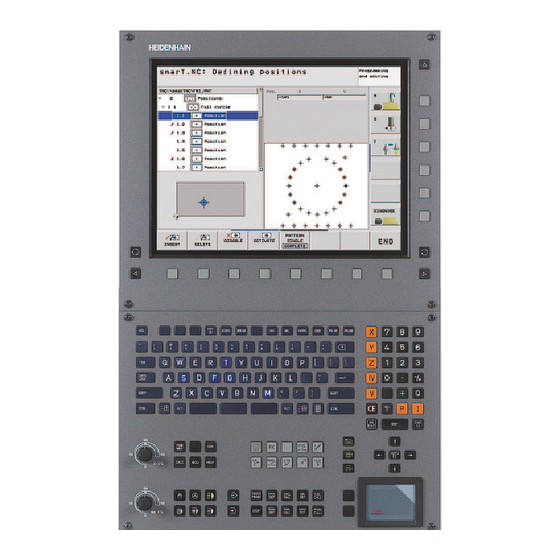
- Page 37 Editing machining positions Header: Operating mode text, error messages Active background mode of operation Tree view in which the defined working patterns are shown in a structured format Form window with the appropriate input parameters Support graphics window, in which the input parameter currently active is displayed Graphics window, in which the programmed machining positions are shown immediately after the form is saved...
- Page 38 Editing contours Header: Operating mode text, error messages 1 4.1 1 4.2 1 4.3 Active background mode of operation Tree view in which the contour elements are shown in a structured format Form window with the various input parameters. In FK programming there can be up to four forms: 4.1: Overview form Contains the input possibilities used most often...
- Page 39 Displaying DXF files Header: Operating mode text, error messages Active background mode of operation Layers or already selected contour elements or positions in the DXF file Drawing window in which smarT.NC shows the DXF file contents...
- Page 40 Mouse operation Using the mouse is also very easy. Please note the following specifics: In addition to the mouse functions familiar from Windows, you can also click the smarT.NC soft keys with the mouse If multiple soft-key rows are present (represented by lines directly above the soft keys), you can activate a row by pressing the corresponding line In the tree view, click the arrows pointing to the right to show detail...
- Page 41 Copying units You can copy individual machining units very easily with the familiar Windows shortcut keys: Ctrl+C to copy the unit Ctrl+X to cut the unit out Ctrl+V to insert the unit behind the active one If you want to copy two or more units at the same time, proceed as follows: Switch to the top level of the soft-key row Use the arrow keys or the mouse to select the first unit...
- Page 42 Tool table editing You can edit the tool table TOOL.T immediately after you have selected the smarT.NC operating mode. The TNC displays the tool data structured in forms. The tool table is navigated in a manner identical to the rest of smarT.NC (see "Navigating in smarT.NC"...
- Page 43 Please also note the detailed description of the tool data in the User's Manual for Conversational Programming. The tool type is used by the TNC to determine the symbol shown in the treeview. Additionally, the TNC also shows the entered tool name in the treeview. On the corresponding tabs, smarT.NC does not show tool data that have been deactivated via machine parameter.
-
Page 44: Mod Function
MOD function The MOD functions provide additional input possibilities and displays. Selecting the MOD functions Press the MOD key for the TNC to display the possible settings in the smarT.NC operating mode Changing the settings Select the desired MOD function in the displayed menu with the arrow keys There are three possibilities for changing a setting, depending on the function selected:... -
Page 45: Defining Machining Operations
(units), which as a rule consist of several programming blocks in conversational format. smarT.NC automatically creates the conversational blocks in the background in an .HU file (HU: HEIDENHAIN Unit program), which looks just like a normal program in conversational format. - Page 46 Optional parameters detail form (4) On the optional parameters detail form you can define additional machining parameters which are not listed on the overview form, such as decrements for drilling or pocket positions for milling. Positions detail form (5) On the positions detail form you can define additional machining positions if the three machining locations on the overview form do not suffice.
- Page 47 Global data detail form (6) The globally effective machining parameters defined in the program header are listed on the global data detail form. If necessary, you can change these parameters for each unit locally.
-
Page 48: Program Settings
Program settings After you have created a new unit program, smarT.NC automatically inserts the Unit 700 Program Settings. The Unit 700 Program Settings must exist in a program, otherwise that program cannot be executed by smarT.NC. The following data must be defined in the program settings: Workpiece blank definition for determining the machining plane and for the graphic simulation Options for selection of the workpiece preset and the datum table to... - Page 49 Global data The global data are divided into six groups: Global data valid everywhere Global data valid only for boring and drilling operations Global data that determine the positioning behavior Global data valid only for milling operations with pocket cycles Global data valid only for milling operations with contour cycles Global data valid only for probing functions As already mentioned, global data are valid for the entire machining...
- Page 50 Changing a global parameter on the global data detail form only effects a local change of the parameter, valid for that one machining step. smarT.NC displays the input fields of locally changed parameters with a red background. On the right side of the input field is an L which identifies the value as valid locally.
- Page 51 Global data valid everywhere Setup clearance: Distance between tool tip and workpiece surface for automated approach of the cycle start position in the tool axis 2nd setup clearance: Position to which smarT.NC positions the tool at the end of a machining step. The next machining position is approached at this height in the machining plane F positioning: Feed rate at which smarT.NC traverses the tool within a cycle...
- Page 52 Global data for drilling operations Retraction rate for chip breaking: Value by which smarT.NC retracts the tool during chip breaking Dwell time at depth: Time in seconds that the tool remains at the hole bottom Dwell time at top: Time in seconds that the tool remains at the setup clearance Global data for milling operations with pocket cycles Overlap factor: The tool radius multiplied by the overlap factor equals...
- Page 53 Global data for milling operations with contour cycles Setup clearance: Distance between tool tip and workpiece surface for automated approach of the cycle start position in the tool axis Clearance height: Absolute height at which the tool cannot collide with the workpiece (for intermediate positioning and retraction at the end of the cycle) Overlap factor: The tool radius multiplied by the overlap factor equals the lateral stepover...
- Page 54 Tool selection As soon as an input field in the tool selection is active, you can use the TOOL NAME soft key to choose if you want to enter the tool number or tool name. There is also a SELECT soft key for calling a window from which you can select a tool defined in the tool table TOOL.T.
- Page 55 RPM/cutting-speed switchover As soon as an input field for defining the spindle speed is active, you can choose whether the speed will be displayed in rpm or as cutting speed (m/min or ipm). To enter a cutting speed Press the VC soft key: the TNC switches the input field To switch from cutting speed to input in rpm Press the NO ENT key: the TNC deletes the cutting-speed input To enter rpm: use the arrow key to move back to the input field...
- Page 56 Selecting data from similar, previously defined units After you have started a new unit, you can use the SELECT UNIT DATA soft key to transfer all data from a previously defined, similar unit. smarT.NC then uses all values defined in this unit and enters them into the active unit.
- Page 57 Available machining steps (units) After choosing the smarT.NC operating mode, you select the available machining steps with the EDIT soft key. The machining steps are divided into the following main groups: Main group Soft key Page MACHINING Page 58 Boring, drilling, thread machining, milling PROBING Page 126 Probe functions for 3-D touch probes...
- Page 58 Machining main group In the Machining main group you select the following machining groups: Machining group Soft key Page DRILLING Page 59 Centering, drilling, reaming, boring, back boring THREAD Page 72 Tapping with floating tap holder, rigid tapping, thread milling POCKETS/STUDS Page 87 Bore milling, rectangular pockets, circular...
- Page 59 Drilling machining group The following working units are available for drilling operations in the Drilling machining group: Unit Soft key Page Unit 240 Centering Page 60 Unit 205 Drilling Page 62 Unit 201 Reaming Page 64 Unit 202 Boring Page 66 Unit 204 Back Boring Page 68 Unit 241 Single-Fluted Deep-Hole Drilling...
-
Page 60: Unit 240 Centering
Unit 240 Centering Parameters on the overview form: T: Tool number or name (switchable via soft key) S: Spindle speed [rpm] or cutting speed [m/min or ipm] F: Centering feed rate [mm/min] or FU [mm/rev] Select Depth/Diameter: Select whether centering is based on the depth or diameter Diameter: Centering diameter. - Page 61 Globally effective parameters on the global data detail form: Setup clearance 2nd setup clearance Dwell time at depth Feed rate for traversing between machining positions...
-
Page 62: Unit 205 Drilling
Unit 205 Drilling Parameters on the overview form: T: Tool number or name (switchable via soft key) S: Spindle speed [rpm] or cutting speed [m/min or ipm] F: Drilling feed rate [mm/min] or FU [mm/rev] Depth: Drilling depth Plunging depth: Dimension by which the tool plunges in each infeed before retraction from the hole Chip breaking depth: Depth at which smarT.NC carries out chip breaking... - Page 63 Additional parameters on the drilling parameters detail form: Chip breaking depth: Depth at which smarT.NC carries out chip breaking Decrement: Value by which smarT.NC decreases the plunging depth Min. infeed: If a decrement has been entered: Limit for minimum infeed Upper adv.stop dist.: Upper setup clearance for repositioning after chip breaking Lower adv.stop dist.: Lower setup clearance for repositioning after...
-
Page 64: Unit 201 Reaming
Unit 201 Reaming Parameters on the overview form: T: Tool number or name (switchable via soft key) S: Spindle speed [rpm] or cutting speed [m/min or ipm] F: Reaming feed rate [mm/min] or FU [mm/rev] Depth: Reaming depth Machining positions (see “Defining Machining Positions” on page 149) Additional parameters on the tool detail form: DL: Delta length for tool T M function: Any miscellaneous function M... - Page 65 Additional parameters on the drilling parameters detail form: None Globally effective parameters on the global data detail form: Setup clearance 2nd setup clearance Retraction feed rate Dwell time at depth Feed rate for traversing between machining positions...
-
Page 66: Unit 202 Boring
Unit 202 Boring Parameters on the overview form: T: Tool number or name (switchable via soft key) S: Spindle speed [rpm] or cutting speed [m/min or ipm] F: Drilling feed rate [mm/min] or FU [mm/rev] Depth: Boring depth Disengaging direction: Direction in which smarT.NC moves the tool away from the counterbore floor Machining positions (see “Defining Machining Positions”... - Page 67 Additional parameters on the drilling parameters detail form: Angle of spindle: Angle to which smarT.NC positions the tool before retracting it Globally effective parameters on the global data detail form: Setup clearance 2nd setup clearance Retraction feed rate Dwell time at depth Feed rate for traversing between machining positions...
-
Page 68: Unit 204 Back Boring
Unit 204 Back Boring Parameters on the overview form: T: Tool number or name (switchable via soft key) S: Spindle speed [rpm] or cutting speed [m/min or ipm] F: Drilling feed rate [mm/min] or FU [mm/rev] Countersinking depth: Depth of cavity Material thickness: Thickness of the workpiece Off-center distance: Off-center distance of the boring bar Tool edge height: Distance between the underside of the boring bar... - Page 69 Additional parameters on the drilling parameters detail form: Angle of spindle: Angle at which smarT.NC positions the tool before it is plunged into or retracted from the bore hole Dwell time: Dwell time at counterbore floor Globally effective parameters on the global data detail form: Setup clearance 2nd setup clearance Feed rate for positioning...
-
Page 70: Unit 241 Single-Fluted Deep-Hole Drilling
Unit 241 Single-Fluted Deep-Hole Drilling Parameters on the overview form: T: Tool number or name (switchable via soft key) S: Spindle speed [rpm] during drilling F: Drilling feed rate [mm/min] or FU [mm/rev] Depth: Drilling depth. Infeed start point: Starting point of metal removal. The TNC moves at the feed rate for pre-positioning from the setup clearance to the deepened starting point Rotat. - Page 71 Additional parameters on the tool detail form: DL: Delta length for tool T M function: Any miscellaneous function M Tool preselect: If needed, this is the number of the next tool for faster tool change (machine-dependent) Additional parameters on the drilling parameters detail form: Dwell depth: Coordinate in the spindle axis at which the tool is to dwell.
- Page 72 Thread machining group The following units are available for thread operations in the Thread machining group: Unit Soft key Page Unit 206 Tapping with a Floating Tap Holder Page 73 Unit 209 Rigid Tapping (also with chip Page 75 breaking) Unit 262 Thread Milling Page 77 Unit 263 Thread Milling / Countersinking...
-
Page 73: Unit 206 Tapping With A Floating Tap Holder
Unit 206 Tapping with a Floating Tap Holder Parameters on the overview form: T: Tool number or name (switchable via soft key) S: Spindle speed [rpm] or cutting speed [m/min or ipm] F: Drilling feed rate: Calculate from S multiplied by thread pitch p Depth of thread: Depth of the thread Machining positions (see “Defining Machining Positions”... - Page 74 Additional parameters on the drilling parameters detail form: None Globally effective parameters on the global data detail form: Setup clearance 2nd setup clearance Dwell time at depth Feed rate for traversing between machining positions...
-
Page 75: Unit 209 Rigid Tapping
Unit 209 Rigid Tapping Parameters on the overview form: T: Tool number or name (switchable via soft key) S: Spindle speed [rpm] or cutting speed [m/min or ipm] Depth of thread: Depth of the thread Thread pitch: Pitch of the thread Machining positions (see “Defining Machining Positions”... - Page 76 Additional parameters on the drilling parameters detail form: Chip breaking depth: Depth at which chip breaking is to occur Angle of spindle: Angle to which smarT.NC positions the tool before thread cutting: This permits regrooving of the thread, if needed S factor for retraction Q403: Factor by which the TNC increases the spindle speed —...
-
Page 77: Unit 262 Thread Milling
Unit 262 Thread Milling Parameters on the overview form: T: Tool number or name (switchable via soft key) S: Spindle speed [rpm] or cutting speed [m/min or ipm] F: Feed rate for milling Diameter: Nominal diameter of the thread Thread pitch: Pitch of the thread Depth: Depth of the thread Machining positions (see “Defining Machining Positions”... - Page 78 Additional parameters on the drilling parameters detail form: Threads per step: Number of thread revolutions by which the tool is offset Globally effective parameters on the global data detail form: Setup clearance 2nd setup clearance Positioning feed rate Feed rate for traversing between machining positions Climb milling, or Up-cut milling...
-
Page 79: Unit 263 Thread Milling / Countersinking
Unit 263 Thread Milling / Countersinking Parameters on the overview form: T: Tool number or name (switchable via soft key) S: Spindle speed [rpm] or cutting speed [m/min or ipm] F: Feed rate for milling F: Countersinking feed rate [mm/min] or FU [mm/rev] Diameter: Nominal diameter of the thread Thread pitch: Pitch of the thread Depth: Depth of the thread... - Page 80 Additional parameters on the drilling parameters detail form: Depth at front: Depth for sinking at front Offset at front: Distance by which the TNC moves the tool center out of the hole during countersinking at front Globally effective parameters on the global data detail form: Setup clearance 2nd setup clearance Positioning feed rate...
-
Page 81: Unit 264 Thread Drilling / Milling
Unit 264 Thread Drilling / Milling Parameters on the overview form: T: Tool number or name (switchable via soft key) S: Spindle speed [rpm] or cutting speed [m/min or ipm] F: Feed rate for milling F: Drilling feed rate [mm/min] or FU [mm/rev] Diameter: Nominal diameter of the thread Thread pitch: Pitch of the thread Depth: Depth of the thread... - Page 82 Additional parameters on the drilling parameters detail form: Chip breaking depth: Depth at which the TNC is to carry out chip breaking during drilling Upper adv. stop dist.: Setup clearance for when the TNC returns the tool to the current plunging depth after chip breaking Depth at front: Depth for sinking at front Offset at front: Distance by which the TNC moves the tool center from the hole center...
-
Page 83: Unit 265 Helical Thread Drilling / Milling
Unit 265 Helical Thread Drilling / Milling Parameters on the overview form: T: Tool number or name (switchable via soft key) S: Spindle speed [rpm] or cutting speed [m/min or ipm] F: Feed rate for milling F: Countersinking feed rate [mm/min] or FU [mm/rev] Diameter: Nominal diameter of the thread Thread pitch: Pitch of the thread Depth: Depth of the thread... - Page 84 Additional parameters on the drilling parameters detail form: None. Globally effective parameters on the global data detail form: Setup clearance 2nd setup clearance Positioning feed rate Feed rate for traversing between machining positions...
-
Page 85: Unit 267 Outside Thread Milling
Unit 267 Thread Milling Parameters on the overview form: T: Tool number or name (switchable via soft key) S: Spindle speed [rpm] or cutting speed [m/min or ipm] F: Feed rate for milling F: Countersinking feed rate [mm/min] or FU [mm/rev] Diameter: Nominal diameter of the thread Thread pitch: Pitch of the thread Depth: Depth of the thread... - Page 86 Additional parameters on the drilling parameters detail form: Threads per step: Number of thread revolutions by which the tool is offset Depth at front: Depth for sinking at front Offset at front: Distance by which the TNC moves the tool center from the stud center Globally effective parameters on the global data detail form: Setup clearance...
- Page 87 Pockets/studs machining group The following units are available for the milling of simple pockets, studs and slots in the pockets/studs machining group: Unit Soft key Page Unit 251 Rectangular Pocket Page 88 Unit 252 Circular Pocket Page 90 Unit 253 Slot Page 92 Unit 254 Circular Slot Page 94...
-
Page 88: Unit 251 Rectangular Pocket
Unit 251 Rectangular Pocket Parameters on the overview form: Machining operation: Select via soft key roughing and finishing, or only roughing, or only finishing T: Tool number or name (switchable via soft key) S: Spindle speed [rpm] or cutting speed [m/min or ipm] F: Feed rate for plunging [mm/min], FU [mm/rev] or FZ [mm/tooth] F: Feed rate for milling [mm/min] or FU [mm/rev] or FZ [mm/tooth] Pocket length: Pocket length in the reference axis... - Page 89 Additional parameters on the pocket parameters detail form: Allowance for side: Finishing allowance for the side Allowance in depth: Finishing allowance for the depth Infeed for finishing: Infeed for finishing on the side. If nothing is entered, finishing is performed in one infeed. F rate for finishing: Feed rate for finishing [mm/min], FU [mm/rev] or FZ [mm/tooth] Angle of rotation: Angle by which the entire pocket is rotated...
-
Page 90: Unit 252 Circular Pocket
Unit 252 Circular Pocket Parameters on the overview form: Machining operation: Select via soft key roughing and finishing, or only roughing, or only finishing T: Tool number or name (switchable via soft key) S: Spindle speed [rpm] or cutting speed [m/min or ipm] F: Feed rate for plunging [mm/min], FU [mm/rev] or FZ [mm/tooth] F: Feed rate for milling [mm/min] or FU [mm/rev] or FZ [mm/tooth] Diameter: Finished diameter of the circular pocket... - Page 91 Additional parameters on the pocket parameters detail form: Allowance for side: Finishing allowance for the side Allowance in depth: Finishing allowance for the depth Infeed for finishing: Infeed for finishing on the side. If nothing is entered, finishing is performed in one infeed F rate for finishing: Feed rate for finishing [mm/min], FU [mm/rev] or FZ [mm/tooth] Globally effective parameters on the global data detail form:...
-
Page 92: Unit 253 Slot
Unit 253 Slot Parameters on the overview form: Machining operation: Select via soft key roughing and finishing, or only roughing, or only finishing T: Tool number or name (switchable via soft key) S: Spindle speed [rpm] or cutting speed [m/min or ipm] F: Feed rate for plunging [mm/min], FU [mm/rev] or FZ [mm/tooth] F: Feed rate for milling [mm/min] or FU [mm/rev] or FZ [mm/tooth] Slot length: Slot length in the reference axis... - Page 93 Additional parameters on the pocket parameters detail form: Allowance for side: Finishing allowance for the side Allowance in depth: Finishing allowance for the depth Infeed for finishing: Infeed for finishing on the side. If nothing is entered, finishing is performed in one infeed F rate for finishing: Feed rate for finishing [mm/min], FU [mm/rev] or FZ [mm/tooth] Angle of rotation: Angle by which the entire pocket is rotated...
-
Page 94: Unit 254 Circular Slot
Unit 254 Circular Slot Parameters on the overview form: Machining operation: Select via soft key roughing and finishing, or only roughing, or only finishing T: Tool number or name (switchable via soft key) S: Spindle speed [rpm] or cutting speed [m/min or ipm] F: Feed rate for plunging [mm/min], FU [mm/rev] or FZ [mm/tooth] F: Feed rate for milling [mm/min] or FU [mm/rev] or FZ [mm/tooth] Center in 1st axis: Center of pitch circle in reference axis... - Page 95 Additional parameters on the tool detail form: DL: Delta length for tool T DR: Delta radius for tool T DR2: Delta radius 2 (corner radius) for tool T M function: Any miscellaneous function M Spindle: Direction of spindle rotation. As a default, smarT.NC sets M3 Tool preselect: If needed, this is the number of the next tool for faster tool change (machine-dependent)
- Page 96 Additional parameters on the pocket parameters detail form: Allowance for side: Finishing allowance for the side Allowance in depth: Finishing allowance for the depth Infeed for finishing: Infeed for finishing on the side If nothing is entered, finishing is performed in one infeed F rate for finishing: Feed rate for finishing [mm/min], FU [mm/rev] or FZ [mm/tooth] Stepping angle: Angle by which the entire slot is rotated further...
-
Page 97: Unit 256 Rectangular Stud
Unit 256 Rectangular Stud Parameters on the overview form: T: Tool number or name (switchable via soft key) S: Spindle speed [rpm] or cutting speed [m/min or ipm] F: Feed rate for plunging [mm/min], FU [mm/rev] or FZ [mm/tooth] F: Feed rate for milling [mm/min] or FU [mm/rev] or FZ [mm/tooth] Stud length: Stud length in the reference axis Workpiece blank length: Blank length in the reference axis Stud width: Stud width in the minor axis... - Page 98 Additional parameters on the stud parameters detail form: Allowance for side: Finishing allowance for the side Angle of rotation: Angle by which the entire stud is rotated Stud position: Position of the stud referenced to the programmed position Globally effective parameters on the global data detail form: Setup clearance 2nd setup clearance Overlap factor...
-
Page 99: Unit 257 Circular Stud
Unit 257 Circular Stud Parameters on the overview form: T: Tool number or name (switchable via soft key) S: Spindle speed [rpm] or cutting speed [m/min or ipm] F: Feed rate for plunging [mm/min], FU [mm/rev] or FZ [mm/tooth] F: Feed rate for milling [mm/min] or FU [mm/rev] or FZ [mm/tooth] Finished diameter: Finished diameter of the circular stud Workpiece blank diameter: Workpiece blank diameter of the circular stud... - Page 100 Additional parameters on the pocket parameters detail form: K Allowance for side: Finishing allowance for the side Globally effective parameters on the global data detail form: Setup clearance 2nd setup clearance Overlap factor Feed rate for traversing between machining positions Climb milling, or Up-cut milling...
-
Page 101: Unit 208 Bore Milling
Unit 208 Bore Milling Parameters on the overview form: T: Tool number or name (switchable via soft key) S: Spindle speed [rpm] or cutting speed [m/min or ipm] F: Feed rate for milling [mm/min] or FU [mm/rev] or FZ [mm/tooth] Diameter: Nominal diameter of the hole Depth: Milling depth Plunging depth: Depth of the tool plunge with each helix (360°) - Page 102 Additional parameters on the drilling parameters detail form: Predrilled diameter: Enter if pre-drilled holes are to be machined again. This allows you to rough-mill holes more than twice as large as the tool diameter Globally effective parameters on the global data detail form: Setup clearance 2nd setup clearance Feed rate for traversing between machining positions...
- Page 103 Contour Program machining group The following units for milling pockets and contour trains of any shape are available in the Contour Program machining group: Unit Soft key Page Unit 122 Contour Pocket Rough-Out Page 104 Unit 22 Contour Pocket Fine Roughing Page 108 Unit 123 Contour Pocket Floor Finishing Page 110...
-
Page 104: Unit 122 Contour Pocket Rough-Out
Unit 122 Contour Pocket The Contour Pocket unit is used to rough out pockets, which may contain islands, of any shape. If necessary, you can assign every subcontour its own depth (FCL 2 function) in the contour detail form. In this case you must always begin with the deepest pocket. - Page 105 Specify via soft key for each subcontour whether it is a pocket or an island. As a rule, always start the list of subcontours with the deepest pocket! On the contour detail form you can define up to a maximum of nine subcontours.
- Page 106 Additional parameters on the tool detail form: DL: Delta length for tool T DR: Delta radius for tool T DR2: Delta radius 2 (corner radius) for tool T M function: Any miscellaneous function M Spindle: Direction of spindle rotation. As a default, smarT.NC sets M3 Tool preselect: If needed, this is the number of the next tool for faster tool change (machine-dependent) Additional parameters on the milling parameters detail form:...
- Page 107 Additional parameters on the contour detail form: Depth: Separately definable depths for each subcontour (FCL 2 function) As a rule, always start the list of subcontours with the deepest pocket! If the contour is defined as an island, the TNC interprets the entered depth as the island height.
-
Page 108: Unit 22 Contour Pocket Fine Roughing
Unit 22 Fine Roughing With the fine roughing unit you can use a smaller tool to rework a contour pocket that has been roughed-out with unit 122. In this step, smarT.NC machines only the places the previous tool did not reach. Parameters on the overview form: T: Tool number or name (switchable via soft key) S: Spindle speed [rpm] or cutting speed [m/min or ipm]... - Page 109 Additional parameters on the milling parameters detail form: Fine roughing strategy. This parameter is only effective if the radius of the fine roughing tool is larger than half the radius of the coarse roughing tool: Between areas that need to be fine-roughed, move the tool along the contour at the current depth Between areas that need to be fine-roughed, retract the tool to safety clearance and move to the starting point of the...
-
Page 110: Unit 123 Contour Pocket Floor Finishing
Unit 123 Contour Pocket Floor Finishing With the floor finishing unit you can finish the floor of a contour pocket that has been roughed-out with unit 122. Always run the floor finishing operation before side finishing! Parameters on the overview form: T: Tool number or name (switchable via soft key) S: Spindle speed [rpm] or cutting speed [m/min or ipm] F: Feed rate for plunging [mm/min], FU [mm/rev] or FZ [mm/tooth]... -
Page 111: Unit 124 Contour Pocket Side Finishing
Unit 124 Contour Pocket Side Finishing The Side Finishing unit is used to finish the side of a contour pocket that has been roughed-out with unit 122. Always run the side finishing operation after floor finishing! Parameters on the overview form: T: Tool number or name (switchable via soft key) S: Spindle speed [rpm] or cutting speed [m/min or ipm] F: Feed rate for plunging [mm/min], FU [mm/rev] or FZ [mm/tooth]... - Page 112 Additional parameters on the milling parameters detail form: Finishing allowance for side: Finishing allowance for finishing in two or more steps Globally effective parameters on the global data detail form: Climb milling, or Up-cut milling...
-
Page 113: Unit 125 Contour Train
Unit 125 Contour Train The Contour Train unit is used to machine open and closed contours that you defined in an .HC program or generated with the DXF converter. Choose start and end points of the contour that leave enough space for tool approach and departure! Parameters on the overview form: T: Tool number or name (switchable via soft key) - Page 114 Center angle (Only in effect if tangential approach on a circular path was selected): Angle of the circular arc Distance to aux. point (Only in effect if tangential approach on a straight path or vertical approach was selected): Distance to the auxiliary point from which the contour is approached Contour name: Name of the contour file (.HC) to be machined.
- Page 115 Additional parameters on the tool detail form: DL: Delta length for tool T DR: Delta radius for tool T DR2: Delta radius 2 (corner radius) for tool T M function: Any miscellaneous function M Spindle: Direction of spindle rotation. As a default, smarT.NC sets M3 Tool preselect: If needed, this is the number of the next tool for faster tool change (machine-dependent) Additional parameters on the milling parameters detail form:...
-
Page 116: Unit 275 Trochoidal Contour Train
Unit 275 Contour Slot The Contour Slot unit is used to machine open and closed contour slots that you defined in an .HC program or generated with the DXF converter. Parameters on the overview form: T: Tool number or name (switchable via soft key) S: Spindle speed [rpm] or cutting speed [m/min or ipm] F: Feed rate for plunging [mm/min], FU [mm/rev] or FZ [mm/tooth] F: Feed rate for milling [mm/min] or FU [mm/rev] or FZ [mm/tooth]... - Page 117 Additional parameters on the tool detail form: DL: Delta length for tool T DR: Delta radius for tool T DR2: Delta radius 2 (corner radius) for tool T M function: Any miscellaneous function M Spindle: Direction of spindle rotation. As a default, smarT.NC sets M3 Tool preselect: If needed, this is the number of the next tool for faster tool change (machine-dependent) Additional parameters on the milling parameters detail form:...
-
Page 118: Unit 130 Contour Pocket On Point Pattern
Unit 130 Contour Pocket on Point Pattern (FCL 3 Function) This unit is used to align on any pattern and rough out pockets, which may contain islands, of any shape. If necessary, you can assign every subcontour its own depth (FCL 2 function) in the contour detail form. - Page 119 Positions or point pattern: Define the positions at which the TNC is to machine the contour pocket (see “Defining Machining Positions” on page 149) Specify via soft key for each subcontour whether it is a pocket or an island. As a rule, always start the list of subcontours with a pocket (if required, the deepest pocket)! On the contour detail form you can define up to a maximum of nine subcontours.
- Page 120 Additional parameters on the tool detail form: DL: Delta length for tool T DR: Delta radius for tool T DR2: Delta radius 2 (corner radius) for tool T M function: Any miscellaneous function M Spindle: Direction of spindle rotation. As a default, smarT.NC sets M3 Tool preselect: If needed, this is the number of the next tool for faster tool change (machine-dependent) Additional parameters on the milling parameters detail form:...
- Page 121 Additional parameters on the contour detail form: Depth: Separately definable depths for each subcontour (FCL 2 function) As a rule, always start the list of subcontours with the deepest pocket! If the contour is defined as an island, the TNC interprets the entered depth as the island height.
- Page 122 Surfaces machining group The following unit is available for surfacing operations in the surfaces machining group: Unit Soft key Page Unit 232 Face Milling Page 123...
- Page 123 Unit 232 Face Milling Parameters on the overview form: T: Tool number or name (switchable via soft key) S: Spindle speed [rpm] or cutting speed [m/min or ipm] F: Feed rate for milling [mm/min] or FU [mm/rev] or FZ [mm/tooth] Milling plan: Selection of the milling plan Starting point in 1st axis: Starting point in the reference axis Starting point in 2nd axis: Starting point in the minor axis...
- Page 124 Additional parameters on the tool detail form: DL: Delta length for tool T DR: Delta radius for tool T DR2: Delta radius 2 (corner radius) for tool T M function: Any miscellaneous function M Spindle: Direction of spindle rotation. As a default, smarT.NC sets M3 Tool preselect: If needed, this is the number of the next tool for faster tool change (machine-dependent) Additional parameters on the milling parameters detail form:...
- Page 125 Globally effective parameters on the global data detail form: Setup clearance 2nd setup clearance Positioning feed rate Overlap factor...
- Page 126 Probing main group In the Probing main group you select the following function groups: Function group Soft key ROTATION Touch probe functions for automatic determination of a basic rotation PRESET Touch probe functions for automatic determination of a reference point MEASURING Touch probe functions for automatic workpiece measurement...
- Page 127 Rotation function group The following units for automatic determination of a basic rotation are available in the Rotation function group: Unit Soft key Unit 400 Rotation around a Straight Line Unit 401 Rotation around two Holes Unit 402 Rotation around two Studs Unit 403 Rotation around a Rotary Axis Unit 405 Rotation around the C Axis...
- Page 128 Preset (Datum) function group The following units for automatic datum setting are available in the Preset function group: Unit Soft key Unit 408 Slot Center Reference Point (FCL 3 Function) Unit 409 Ridge Center Reference Point (FCL 3 Function) Unit 410 Datum Inside Rectangle Unit 411 Datum Outside Rectangle Unit 412 Datum Inside Circle Unit 413 Datum Outside Circle...
- Page 129 Unit Soft key Unit 417 Datum in Touch Probe Axis Unit 418 Datum from 4 Holes Unit 419 Datum in One Axis...
- Page 130 Measuring function group The following units for automatic workpiece measurement are available in the Measuring function group: Unit Soft key Unit 420 Measure Angle Unit 421 Measure Hole Unit 422 Measure Cylindrical Stud Unit 423 Measure Rectangle Inside Unit 424 Measure Rectangle Outside Unit 425 Measure Width Inside Unit 426 Measure Width Outside Unit 427 Measure Coordinate...
- Page 131 Unit Soft key Unit 430 Measure Bolt Hole Circle Unit 431 Measure Plane...
- Page 132 Special functions function group The following units are available in the special functions function group: Unit Soft key Unit 441 Touch Probe Parameters Unit 460 Calibrate 3-D Touch Probe...
- Page 133 Kinematics measurement function group (option) The following units are available in the kinematics function group: Unit Soft key Unit 450 Save/Restore Kinematics Unit 451 Test/Optimize Kinematics Unit 452 Preset Compensation Unit 460 Calibrate 3-D Touch Probe...
- Page 134 Tool function group The following units for automatic tool measurement are available in the Tool function group: Unit Soft key Unit 480 TT: Calibrate TT Unit 481 TT: Measure Tool Length Unit 482 TT: Measure Tool Radius Unit 483 TT: Measure Entire Tool...
- Page 135 Conversion main group The following functions for coordinate transformation are available in the Conversion main group: Function Soft key Page UNIT 141 (FCL 2 FUNCTION): Page 136 Datum shift UNIT 8 (FCL 2 function): Page 137 Mirroring UNIT 10 (FCL 2 function): Page 137 Rotation UNIT 11 (FCL 2 function):...
- Page 136 Unit 141 Datum Shift Unit 141 Datum Shift is used to define a datum shift with the direct input of shift values in the specific axes, or by definition of a number from the datum table. You need to have specified the datum table in the program header.
- Page 137 Unit 8 Mirroring (FCL 2 function) With unit 8 you use check boxes to define the desired mirrored axes. If you define only one mirrored axis, the TNC changes the machining direction. Reset mirroring: Define unit 8 without mirrored axes. Unit 10 Rotation (FCL 2 function) Unit 10 Rotation is used to define an angle of rotation by which smarT.NC rotates the subsequently defined operations in the active working plane.
- Page 138 Unit 11 Scaling (FCL 2 function) Unit 11 is used to define a scaling factor with which you can run the subsequently defined operations with enlarged or reduced dimensions. Use machine parameter MP7411 to specify whether the scaling factor is to be effective only in the active working plane or also in the tool axis.
- Page 139 Unit 140 Tilt Plane (FCL 2 function) The machine manufacturer must enable the functions for tilting the working plane! You can only use the PLANE function on machines that have at least two tilting axes (head and/or table). Exception: The PLANE AXIAL function (FCL 3 function) can also be used if only a single rotary axis is present or active on your machine.
- Page 140 The following plane definitions are available: Type of plane definition Soft key Plane defined by spatial angle Plane defined by projection angle Plane defined by Euler angle Plane defined by vector Plane defined by three points Define an incremental spatial angle Define axis angles (FCL3 function) Reset the tilted plane function You can use soft keys to switch the positioning behavior, the selection of...
- Page 141 Unit 247 New Datum Unit 247 is used to define a reference point from the active preset table.
- Page 142 Unit 7 Datum shift (FCL 2 function) Before you use unit 7 you must select in the program head the datum table in which smarT.NC will apply the datum numbers (see “Program settings” on page 48). Reset datum shift: Define unit 7 with number 0. Ensure that in line 0 all coordinates are defined as 0.
- Page 143 Special functions main group The following varied functions are available in the special functions main group: Function Soft key Page UNIT 151: Page 144 Program call UNIT 799: Page 145 Program end unit UNIT 70: Page 146 Enter positioning block UNIT 60: Page 147 Enter miscellaneous functions M...
- Page 144 Unit 151 Program Call From smarT.NC you use this unit to call any program of the following file type: smarT.NC unit program (file type .HU) Conversational dialog program (file type .H) ISO program (file type .I) Parameters in the overview form: Program Name: Enter the path and name of the program to be called.
- Page 145 Unit 799 Program End This unit is used to designate the end of a unit program. You can define miscellaneous functions M and alternatively a position that the TNC should approach. Parameters: M function: If desired, enter any miscellaneous functions M. The TNC automatically enters M2 (program end) with defining process Approach end position: If desired, enter a position to be approached at program end.
- Page 146 Unit 70 Positioning This unit is used to define a positioning movement that the TNC should run between any units. Parameters: Approach end position: If desired, enter a position to be approached by the TNC. Positioning sequence: First the tool axis (Z), then the machining plane (X/Y) Workpiece reference system: Coordinates entered are referenced to the active workpiece datum...
- Page 147 Unit 60 M Function This unit is used to define any two miscellaneous functions M. Parameters: M function: Input of any miscellaneous functions M Unit 50 Separate Tool Call This unit is used to define a separate tool call. Parameters in the overview form: T: Tool number or name (switchable via soft key) S: Spindle speed [rpm] or cutting speed [m/min or ipm] DL: Delta length for tool T...
- Page 148 Unit 40 Conversational Programming Use this unit to insert conversational dialog sequences between machining blocks. It can always be used in the following cases: You require TNC functions for which form entry is not yet available You want to define OEM cycles There is no limit to the number of conversational programming blocks that can be entered per conversational dialog sequence.
-
Page 149: Defining Machining Positions
Defining Machining Positions Fundamentals On the overview form (1) you can directly define the machining positions of the current machining step in Cartesian coordinates (see figure at top right). If machining is to be performed at more than three positions or with machining patterns, you can define up to six more positions—for a total of nine—on the Positions detail form (2). - Page 150 Using machining positions repeatedly You can use machining positions for all programmed machining units that directly follow, regardless of whether you have created these machining positions directly on the form or as an HP file in the pattern generator. Just leave the input fields for the machining positions empty. smarT.NC then automatically uses the machining positions previously defined by you.
- Page 151 Defining machining patterns on the Positions detail form Select any machining unit Select Positions detail form Select the desired machining pattern via soft key After you have defined a machining pattern, the smarT.NC displays a note with accompanying graphic on the Overview form instead of the input values due to reasons of space.
- Page 152 Single row, straight or rotated Starting point 1st axis: Coordinate of the starting point of the row in the reference axis of the working plane Starting point 2nd axis: Coordinate of the starting point of the row in the minor axis of the working plane Distance: Distance between the machining positions.
- Page 153 Pattern, straight, rotated or distorted Starting point 1st axis: Coordinate of the starting point of the pattern (1) in the major axis of the working plane Starting point 2nd axis: Coordinate of the starting point of the pattern (2) in the minor axis of the working plane Distance in 1st axis: Distance of the machining positions in the major axis of the working plane.
- Page 154 Frame straight, rotated or distorted Starting point 1st axis: Coordinate of the starting point of the frame (1) in the major axis of the working plane Starting point 2nd axis: Coordinate of the starting point of the frame (2) in the minor axis of the working plane Distance in 1st axis: Distance of the machining positions in the major axis of the working plane.
- Page 155 Full circle Center in 1st axis: Coordinate of the circle center point (1) in the major axis of the working plane Center in 2nd axis: Coordinate of the circle center point (2) in the minor axis of the working plane Diameter: Diameter of the bolt hole circle Starting angle: Polar angle of the first machining position.
- Page 156 Circle segment Center in 1st axis: Coordinate of the circle center point (1) in the major axis of the working plane Center in 2nd axis: Coordinate of the circle center point (2) in the minor axis of the working plane Diameter: Diameter of the bolt hole circle Starting angle: Polar angle of the first machining position.
- Page 157 Starting the pattern generator The pattern generator for smarT.NC can be started two different ways: Directly from the third soft-key row of the smarT.NC main menu, if you want to directly define several point files in a row. From the form during the machining definition, if you want to enter machining positions.
- Page 158 Starting the pattern generator from a form Select the smarT.NC operating mode Select any machining step in which machining positions can be defined Select an input field in which a machining position is to be defined (see figure at top right) Switch to Define machining positions in point table To create a new file: Enter the file name (without file type), and confirm with the NEW .HP soft key...
- Page 159 Exiting the pattern generator Press the END key or soft key. smarT.NC opens a pop-up window (see figure at right) Press the ENT key or YES button to save all changes—or to save a newly created file—and to exit the pattern generator Press the NO ENT key or NO button to discard all changes, and to exit the pattern generator Press the ESC key to return to the pattern generator...
- Page 160 Working with the pattern generator Overview The following possibilities are available in the pattern generator for defining machining positions: Function Soft key Page Single point, Cartesian Page 165 Single row, straight or rotated Page 165 Pattern, straight, rotated or distorted Page 166 Frame straight, rotated or distorted Page 167...
- Page 161 Defining a pattern Select via soft key the pattern to be defined Define the required input parameters in the form. Select the next input field with the ENT key or the arrow down key Press the END key to save the entered parameters After you have entered a pattern via a form, smarT.NC displays this pattern symbolically as an icon on the left side of the screen in the tree view (1).
- Page 162 Functions of the pattern generator Function Soft key Hide the pattern or position selected in the tree view for machining. Hidden patterns or positions are marked in the tree view with a red slash, and in the preview graphics with a bright red dot.
- Page 163 Function Soft key Display or hide rulers Go to previous page Go to next page Go to beginning of file Go to end of file Zoom function: Shift zoom area up (last soft-key row) Zoom function: Shift zoom area down (last soft-key row) Zoom function: Shift zoom area to the left (last soft-key row) Zoom function: Shift zoom area to the right (last soft-key...
- Page 164 Function Soft key Zoom function: Reduce the workpiece (last soft-key row) Zoom function: Show workpiece in original size (last soft- key row)
-
Page 165: Single Point, Cartesian
Single point, Cartesian X: Coordinate in the reference axis of the working plane Y: Coordinate in the minor axis of the working plane Single row, straight or rotated Starting point 1st axis: Coordinate of the starting point of the row in the reference axis of the working plane Starting point 2nd axis: Coordinate of the starting point of the row in the minor axis of the working plane Distance: Distance between the machining positions. -
Page 166: Pattern, Straight, Rotated Or Distorted
Pattern, straight, rotated or distorted Starting point 1st axis: Coordinate of the starting point of the pattern (1) in the major axis of the working plane Starting point 2nd axis: Coordinate of the starting point of the pattern (2) in the minor axis of the working plane Distance in 1st axis: Distance of the machining positions in the major axis of the working plane. -
Page 167: Frame Straight, Rotated Or Distorted
Frame straight, rotated or distorted Starting point 1st axis: Coordinate of the starting point of the frame (1) in the major axis of the working plane Starting point 2nd axis: Coordinate of the starting point of the frame (2) in the minor axis of the working plane Distance in 1st axis: Distance of the machining positions in the major axis of the working plane. -
Page 168: Full Circle
Full circle Center in 1st axis: Coordinate of the circle center point (1) in the major axis of the working plane Center in 2nd axis: Coordinate of the circle center point (2) in the minor axis of the working plane Diameter: Circle diameter Starting angle: Polar angle of the first machining position. -
Page 169: Circle Segment
Circle segment Center in 1st axis: Coordinate of the circle center point (1) in the major axis of the working plane Center in 2nd axis: Coordinate of the circle center point (2) in the minor axis of the working plane Diameter: Circle diameter Starting angle: Polar angle of the first machining position. -
Page 170: Change Starting Height
Changing the starting height Top surface coordinate: Coordinate of the top surface of the workpiece If you do not define a starting height in the definition of the machining positions, smarT.NC always sets the coordinate of the workpiece surface to 0. If you change the starting height, then the new starting height is valid for all subsequently programmed machining positions. - Page 171 Defining a retraction height for positioning (FCL 3 Function) Use the arrow keys to select any single position that is to be approached at a height you define. Retraction height: Enter the absolute coordinate at which the TNC is to approach this position. The TNC marks the position with an additional circle.
-
Page 172: Defining Contours
Defining Contours Fundamentals Contours are defined in separate files (file type .HC). Since .HC files contain pure descriptions of contours—only geometry data, no technology data—they can be used flexibly: as contour trains, as pockets or as islands. You can create an HC file either with the path functions or by using the DXF converter (software option) to import it from existing DXF files. - Page 173 Starting the contour programming The contour programming for smarT.NC can be started in two different ways: Directly from the main row of the editing menu, if you want to define several separate contours in a row From the form during the machining definition, when you are supposed to enter the names of the contours to be machined Starting the contour programming from the main row of the editing menu...
- Page 174 Starting contour programming from a form Select the smarT.NC operating mode Select any machining step for which contour programs are required (Unit 122, Unit 125) Select the input field in which the name of the contour program is to be defined (1, see figure) To create a new file: Enter the file name (without file type), and confirm with the NEW soft key Specify the units of measurement for the new contour...
- Page 175 Exiting the contour programming Press the END key: smarT.NC exits the contour programming and returns to the state from which you started contour programming: Either to the last active .HU program, if you started from the smarT.NC main row, or to the entry form of the machining step, if you started from the form.
- Page 176 Working with contour programming Overview The contour elements are programmed using the familiar conversational dialog functions. Along with the gray path functions keys, the powerful FK free contour programming is also available. These forms are called via soft keys. The support graphics, which are available for each input field and clarify which parameter is to be entered, are especially helpful for FK programming.
- Page 177 FK free contour programming Workpiece drawings that are not dimensioned for NC often contain unconventional coordinate data that cannot be entered with the gray path function keys. You can enter such dimensional data directly by using the FK free contour programming function.
- Page 178 Functions of the programming graphics Function Soft key Generate a complete graphic Generate programming graphic blockwise Generate a complete graphic or complete it after RESET + START Stop the programming graphics. This soft key only appears while the TNC is generating the interactive graphics.
- Page 179 The different colors of the displayed contour elements indicate their validity: Blue The contour element is fully defined Green The entered data describe a limited number of possible solutions: select the correct one The entered data are not sufficient to determine the contour element: enter further data Selecting from multiple possible solutions If incomplete entries lead to multiple theoretically possible solutions,...
- Page 180 Functions available for contour programming Function Soft key Assume the workpiece-blank definition from the .HU program if you called the contour programming from a smarT.NC unit Display or hide the block numbers Redraw the programming graphics, for example if lines were deleted by intersections Clear programming graphics Graphically display programmed contour elements...
- Page 181 Converting existing conversational dialog programs into contour programs In this procedure you must copy an existing conversational dialog program (.H file) into a contour description (.HC file). Since the two file types have a different internal data format, an ASCII file must be created as an intermediary for this copy procedure.
-
Page 182: Processing Dxf Files (Software Option)
Processing DXF Files (Software Option) Function DXF files created in a CAD system can be opened directly by the TNC, in order to extract contours or machining positions, and save them as conversational programs or as point files. Plain-language programs acquired in this manner can also be run by older TNC controls, since these contour programs contain only L and CC/C blocks. - Page 183 The DXF files to be processed must be stored on the hard disk of your TNC. Before loading the file to the TNC, ensure that the name of the DXF file does not contain any blank spaces or impermissible special characters. The DXF file to be opened must contain at least one layer.
-
Page 184: Opening A Dxf File
Opening a DXF file The DXF converter can be started in different ways: From the file management if you want to extract several contour or position files consecutively From the form during the machining definition of units 125 (contour train), 122 (contour pocket) and 130 (contour pocket on point pattern) if you are supposed to enter the names of the contours to be machined While defining the machining, if you enter the machining positions via point files... - Page 185 Starting the DXF converter through the file management Select the smarT.NC operating mode Call the file manager In order to see the soft-key menu for selecting the file type to be displayed, press the SELECT TYPE soft key In order to show all DXF files, press the SHOW DXF soft key Select the desired DXF file, and load it with the ENT key.
- Page 186 Starting the DXF converter from a form Select the smarT.NC operating mode Select any machining step for which contour programs or point files are necessary Select the input field in which the name of the contour program or point file is to be defined To start the DXF converter: Press the SHOW DXF soft key.
-
Page 187: Basic Settings
Basic settings The third soft-key row has various possibilities for settings: Setting Soft key Show/hide rulers: The TNC shows the rulers at the left and top edges of the drawing. The values shown on the ruler are based on the drawing datum. Show/hide status bar: The TNC shows the status bar at the bottom edge of the drawing. - Page 188 Setting Soft key Mode for point assumption with circles and arcs: The mode determines whether the TNC automatically assumes the circle center point when selecting machining positions via mouse click (OFF), or if additional points on the circle should be shown as well.
-
Page 189: Layer Settings
Layer settings As a rule, DXF files contain multiple layers, with which the designer organizes the drawing. The designer uses the layers to create groups of various types of elements, such as the actual workpiece contour, dimensions, auxiliary and design lines, shadings, and texts. So that as little unnecessary information as possible appears on the screen during selection of the contours, you can hide all excessive layers contained in the DXF file. -
Page 190: Specifying The Reference Point
Specifying the reference point The datum of the drawing for the DXF file is not always located in a manner that lets you use it directly as a reference point for the workpiece. Therefore, the TNC has a function with which you can shift the drawing datum to a suitable location by clicking an element. - Page 191 Selecting a reference point on a single element Select the mode for specifying the reference point Click the element on which you want to set the reference point with the left mouse button. The TNC indicates possible locations for reference points on the selected element with stars Click the star you want to select as reference point.
- Page 192 Element information At the bottom left of the screen, the TNC shows how far the reference point you haven chosen is located from the drawing datum.
- Page 193 Contour selection, saving a contour program You must use the touchpad on the TNC keyboard or a mouse attached via the USB port in order to select a contour. Select the first contour element such that approach without collision is possible. If the contour elements are very close to one another, use the zoom function.
- Page 194 If you have selected polylines, the TNC shows a two-level ID number in the left window. The first number is the serial contour element number, the second element is the element number of the respective polyline from the DXF file. To save the selected contour elements in a plain-language program, enter any file name in the pop-up window displayed by the TNC.
- Page 195 Dividing, extending and shortening contour elements If contour elements to be selected in the drawing connect poorly, then you must first divide the contour element. This function is automatically available if you are in the mode for selecting a contour. Proceed as follows: The poorly connecting contour element is selected, so it is colored blue.
- Page 196 Element information At the bottom left of the screen, the TNC displays information about the contour element that you last selected via mouse click in the left or right window. Straight line End point of the straight line, and the starting point is grayed out Circle or arc Circle center point, circle end point, and direction of rotation.
-
Page 197: Selecting And Storing Machining Positions
Selecting and storing machining positions You must use the touchpad on the TNC keyboard or a mouse attached via the USB port in order to select a machining position. If the positions to be selected are very close to one another, use the zoom function. - Page 198 Individual selection Select the mode for choosing a machining position. The TNC hides the layers shown in the left window, and the right window becomes active for position selection. In order to select a machining position, click the desired element with the left mouse button. The TNC indicates possible locations for machining positions on the selected element with stars.
- Page 199 To save the selected machining positions in a points file, enter any file name in the pop-up window displayed by the TNC. Default setting: Name of the DXF file Confirm the entry: The TNC saves the contour program in the directory in which the DXF file is also saved. If you want to select more machining positions in order to save them in a different file, press the CANCEL SELECTED ELEMENTS soft key and select as described above.
- Page 200 Quick selection of hole positions in an area defined by the mouse Select the mode for choosing a machining position. The TNC hides the layers shown in the left window, and the right window becomes active for position selection. Press the shift key on the keyboard and drag the left mouse key to define an area in which the TNC is to adopt all included circle centers as hole positions: the TNC opens a window in which you can filter the holes by size.
- Page 201 Quick selection of hole positions by entering a diameter Select the mode for choosing a machining position. The TNC hides the layers shown in the left window, and the right window becomes active for position selection. Select the last soft-key row Open the dialog for diameter input: enter any diameter in the pop-up window displayed by the TNC Enter the desired diameter and confirm it with the ENT key:...
- Page 202 To save the selected machining positions in a points file, enter any file name in the pop-up window displayed by the TNC. Default setting: Name of the DXF file. If the name of the DXF file contains special characters or spaces, the TNC replaces the characters with underscores.
- Page 203 Filter settings After you have used the quick selection function to mark hole positions, a pop-up window appears in which the smallest diameter found is to the left and the largest diameter to the right. With the buttons just below the diameter display you can adjust the smallest diameter in the left area and largest in the right area so that you can load the hole diameters that you want.
- Page 204 Filter setting of largest diameter Soft key Display the smallest diameter found. The TNC sets the filter for the largest diameter to the value set for the smallest diameter. Display the next smaller diameter found Display the next larger diameter found Display the largest diameter found (default setting) With the apply path optimization option on (default setting), the TNC...
- Page 205 Element information At the bottom left of the screen, the TNC displays the coordinates of the machining position that you last selected via mouse click in the left or right window. Undoing actions You can undo the four most recent actions that you have taken in the mode for selecting machining positions.
-
Page 206: Zoom Function
Zoom function The TNC features a powerful zoom function for easy recognition of small details during contour or point selection. Function Soft key Magnify workpiece. The TNC always magnifies the center of the view currently being displayed. Use the scroll bars to position the drawing in the window so that the desired section appears after the soft key has been pressed. -
Page 207: Graphically Testing And Running A Unit Program
Graphically Testing and Running a Unit Program Programming graphics The interactive programming graphics are only available for creation of a contour program (.HC file). The TNC can generate a two-dimensional graphic of the contour while you are programming it: Generate a complete graphic Generate programming graphic blockwise Start and complete the graphic Automatic graphic generation during programming... - Page 208 Test graphics and execution graphics Select the GRAPHICS or PROGRAM+GRAPHICS layout. The TNC can graphically display a machining operation in the Test Run and Program Run submodes of operation. The following functions are available via soft key: Plan view Projection in three planes 3-D view Run a program test up to a certain block Test the entire program...
- Page 209 Activate/Deactivate function for measuring machining time Consider or ignore program blocks preceded by a slash Select the stopwatch functions Set the simulation speed Functions for section magnification Functions for the sectional planes Functions for rotating and magnifying/reducing...
-
Page 210: Status Displays
Status displays Select the PROGRAM+STATUS screen layout. In the program run modes a window in the lower part of the screen shows information on Tool position Feed rate Active miscellaneous functions By pressing the soft keys or clicking the tabs you can let further status information be displayed in a screen window: Activate Overview tab: Display of the most important status information... - Page 211 Running a unit program You can run UNIT programs (*.HU) in the smarT.NC operating mode, or in the usual Program Run, Single Block or Program Run, Full Sequence operating modes. When the “smarT.NC: Program run” operating mode is selected, the TNC automatically deactivates all global program-run settings that you have activated in the conventional Single Block or Full Sequence program run modes.
- Page 212 Procedure Select the smarT.NC operating mode Select the Program Run submode Press the RUN SINGLE UNIT soft key, or Press the RUN ALL UNITS soft key, or Press the RUN ACTIVE UNIT soft key...
- Page 213 Mid-program startup (block scan, FCL 2 function) Use the mid-program startup function (block scan) to run a part program from any desired line number. The TNC scans the program blocks up to that line number and displays the contour (select the PROGRAM + GRAPHICS screen layout).
- Page 214 Mid-program startup in a point table (FCL 2 function) Select the smarT.NC operating mode Select the Program Run submode Select mid-program startup Enter the line number of the machining unit in which you want to start the program run. Confirm with the ENT key. Then smarT.NC displays the content of the point table in the preview window Select the machining position where you want to resume...
- Page 215 In addition, the following functions are available in the pop-up window: Show/hide preview window Show/hide the program interruption point last saved Load the program interruption point last saved...
- Page 216 HEIDENHAIN (G.B.) Limited 200 London Road, Burgess Hill West Sussex RH15 9RD, United Kingdom { (01444) 247711 | (01444) 870024 533 191-25 · Ver05 · SW06 · 1 · 6/2010 · F&W · Printed in Germany...
Need help?
Do you have a question about the ITNC 530 - PILOT SMART NC and is the answer not in the manual?
Questions and answers